Power line noise has been on the increase for several years, but after a previous experience trying to get a situation like this resolved I had become jaded and lacked interest in going down that road again. Also the process is not easy for personal reasons. However, I ran into an old friend at a hamfest who said he had a contact and believed he could get the power company on it. I was shocked when I got a call from the power company troubleshooter a week later. It remains to be seen how this will play out but the initial contact sounded promising.
I needed a way to find noisy poles and I needed it fast. Strike while the iron is hot, my dad always said! So I ordered an MFJ-856 power line noise meter. For those not familiar with it, this handy device is a wide bandwidth 135 MHz AM receiver mounted on a 3 element yagi. It is very light and easily carried in one hand. Not surprisingly, I took one look and said “needs improvement”. But I went out for a test run anyway, and found it was completely overwhelmed by the intensity of power line noise in my area. It was impossible to get bearings because the antenna pattern nulls weren’t deep enough to bring the meter down from full scale.
I decided it needed three changes:
1) Get the receiver out of the center of the yagi
2) Improve the yagi feed method
3) Add switchable attenuators
First I modeled the yagi in YO and found it had a reasonable pattern as designed. No major changes would be needed other than to the driven element. Next I confirmed by experiment that placing objects or wires in the center of the yagi had a detrimental affect on real world pattern. I also confirmed that placing objects or wires behind the reflector had little or no affect. Great! Now I had a plan!
 I added a T match to the driven element. The T bars are 11.5 inches long #10 AWG copper spaced 1.0625 inches from the driven element, center to center. With shorting bars at 11 inches out from center this produced a nearly perfect SWR at 135 MHz. It is important to note the driven element had been modified slightly. Instead of mounting each element half through the boom using a #10-32 machine screw and hardware, a length of #10-32 all-thread is passed through the forward hole with a nut on each side to secure it. Then the halves of the driven element are screwed onto the all-thread in the same manner as the parasitic elements.
  Driven element tube lengths did not need to be changed with this mounting arrangement. The balun is 30.5 inches of RG-303 coax, with the entire center block assembly on an SO-239 with small aluminum angle bracket, attached to the boom with a single #8-32 machine screw.
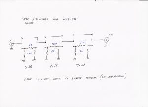
 A short length of RG-142B/U coax runs rearward from the feed to just behind the reflector, where it enters a homebrew step attenuator. No connector is used at this point, though one could be if desired. The attenuator uses DPDT slide switches liberated from and old Bell&Howell Schools oscilloscope and standard 1/4 watt 5% metal film resistors. The three attenuator sections are approximately 5, 15, and 25 dB for a total of 45 dB when all are switched in. This is barely adequate in my area! There are times I could use another 20 dB but it’s quite usable on most noises as it is now.
The attenuator is attached to the MFJ receiver using two #4-40 machine screws. The receiver is attached to the boom with two #8-32 machine screws.
Click on the thumbnails to see high resolution pictures. Try to ignore my little helper buddy there! If he sees a camera, he shows up hoping to get his picture taken! Which usually works, because he makes it a point to be wherever the object being photographed is… as you can see here.


