
I have been building and modifying amplifiers for almost as long as I have been a ham. That’s some three and a half decades. It all started back in the early 1980s, shortly after I became a ham. I knew from the outset that DXing and contesting were in my blood. I had a lust for high power but didn’t think I could afford an amplifier. Then I stumbled across a partially built 80 through 10 meter amplifier carcass at a hamfest. I managed to make a deal and brought it home. It had four 811A tubes and needed some work to be complete. So began a learning experience and the first of many amplifier projects. Since then I have built amplifiers for all bands between 160 meters and 70 centimeters, ranging in power from a few hundred watts to legal limit.
During all this time building and using amplifiers I have had my share of glitches. A good number of those involved high voltage arcs which were both destructive and, in many cases, quite frightening! In the early days I didn’t know hipot (high potential) testers existed. Somewhere around the turn of the century Steve, K0XP, educated me (at least partially) on the subject but I did not pick up the ball and run with it at that time.
Recently the VHF bug I thought I had eradicated from my system came back with a vengeance. I found myself in possession of a 2 meter transverter and decided to convert my 4CX1500B amplifier from 6 meters back to the band I had originally built it for: 2 meters. I didn’t expect any surprises with this one, since it had worked rather well for me on 2 meters a decade earlier. However, upon completion it arced somewhere, destroying the zener diodes in the screen supply. I made some modifications, replaced the diodes and had yet another arc while testing. After the third such incident I began to wonder if maybe – just maybe – it might be time to build a hipot tester.
After a bit of research I decided to build a 0 to 10,000 volt tester. I spent a day on eBay locating parts and when they arrived another day putting the tester together. A hipot tester is really nothing more than a high voltage (usually variable) power supply with current limiting and current metering. The idea is to determine in a relatively non-destructive way whether a part can withstand the voltage it is rated for or at what voltage a part begins to break down. We are looking to measure current of a few microamps. Hipot testers are current limited so that even if the device under test were to suddenly become a short, the amount of current allowed to flow would not result in big bangs, blinding arcs, catastrophic failure of the tester or the like.
I won’t go into full construction details here. There are a number of hipot tester construction articles on the web and elsewhere. My tester uses a 10,000 volt furnace ignition transformer with a small variac to adjust the voltage and a 100 watt light bulb in series with the primary. The light bulb is for primary current limiting should something go horribly wrong. The high voltage is converted to DC with a half wave rectifier and filtered by a .05 microfarad 10kV glassmike capacitor. There is a 100 megohm, 15 kV rated resistor in series with a 100 microamp meter to read tester voltage (100 microamps equals 10,000 volts). There is a current limiting resistor (at the moment 25 megohms) in series with a large 20 microamp meter to measure current through the device under test.

Front panel of hipot tester
After building this tester I learned right away that microwave oven diodes which claim to be rated for 12 kV probably aren’t. My diode failed (shorted, naturally) around 6000 volts. I was glad I put that light bulb in the transformer primary! It suddenly went from no visible glow whatsoever to near full brilliance when the diode failed. So much for that. Wanting to get on with testing tubes, I grabbed fifteen 1N4007 didoes and wired them in series. It’s not pretty but it works.
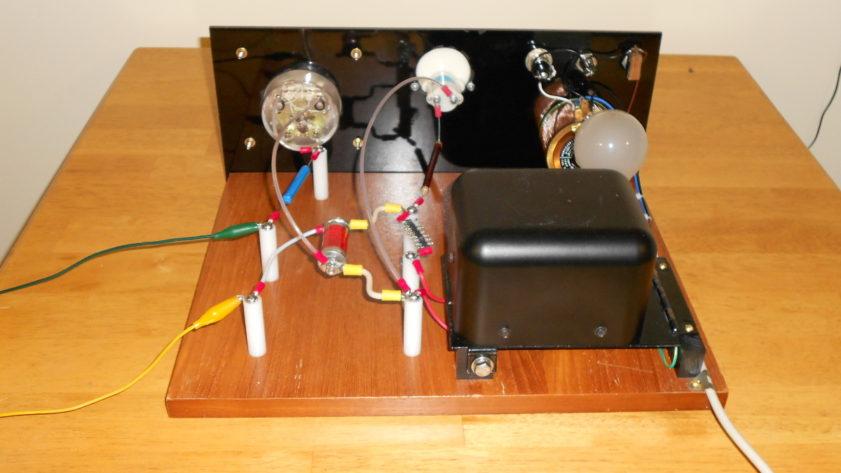
Rear view of hipot tester
The next thing I learned is that with a few thousand volts on that output current meter, its plastic case and internal parts take on an electrostatic charge that causes the pointer to swing upscale even when no current is flowing! Not only that, it remained there for more than an hour after turning off the tester! That wasn’t good. I could not find mention of this problem in any of the hipot tester articles. I decided to solve the issue by moving the meter from the positive side to the negative side of the tester. That way there wouldn’t be several thousand volts on that meter unless the device under test failed. I see no problem with this since current is current. I now wonder why people put the meter in the positive lead. For the most part we stopped doing that with plate current meters on amplifiers a long time ago. Why not with hipot testers?
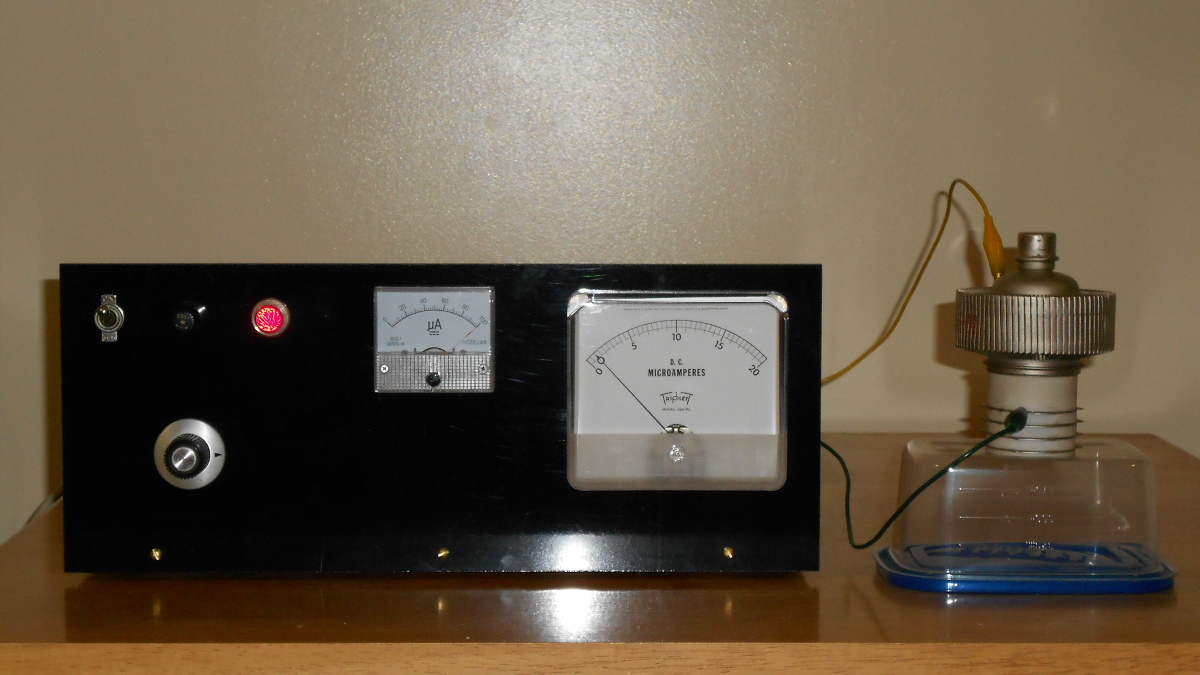
A 4CX1500B tube under test, showing screen grid to plate leakage of about one microamp at 10,000 volts.
The tester is working well and will prove very useful around here. I can now test transmitting tubes, capacitors, transformers and many other parts for leakage or voltage breakdown issues. Please note that i purposely did not say I can safely run these tests! There are risks here! For one thing the tester is not enclosed, leaving 120V AC mains and high voltage circuits exposed where one could come into contact with them. The clip leads used to connect the device under test are no doubt a bad idea at these voltages too. I understand and accept the risks, but I do not suggest others build or operate the tester as shown here.
One additional note I would like to add concerning resistors in high voltage circuits. Most of us are accustomed to selecting resistors based on resistance, power rating and perhaps tolerance. We rarely think about voltage ratings, but resistors do have a maximum voltage that they can withstand, and it may be far less than we think. Let’s look at an example to help illustrate this. The 100 megohm resistor used in the voltage meter circuit of this tester will have 100 microamps flowing through it when the meter is full scale. The math tells us this resistor will need to be able to dissipate one watt (I squared times R). But wait! Your average one watt resistor has a voltage rating that is probably somewhere in the 300 to 500 volt range. In this application it will have 10,000 volts across it when the meter is at full scale reading! Even though a high value resistor (in this case 100 million ohms) may claim to be able to dissipate one watt of heat, we cannot actually get anywhere near that dissipation without exceeding its voltage rating and having it go up in smoke and fire. One solution is to put many resistors in series. If we use resistors rated 500 volts we will need 20 of them in series to be safe in this application. That’s a lot of resistors! Naturally the resistance of would need to be 1/20th of our final value, or 5 megohms. I opted to buy resistors designed for high voltage. IRC, Caddock, and others make such parts. The resistor I selected for this application is made by IRC and is rated for 15,000 volts, 3 watts, 100 megohms. The same caveat applies to the current limiting resistor at the output of the tester. Should a device under test short, that resistor will have the full supply voltage across it.
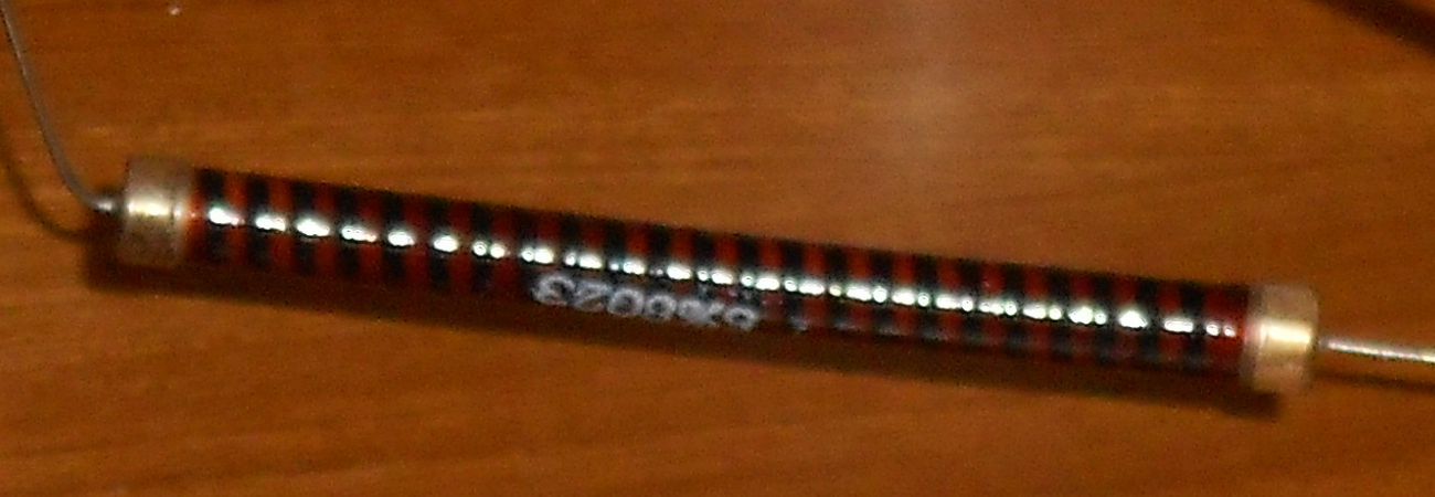
IRC 15,000 volt resistor. Its body is three inches long and it uses a spiral wound resistive element to withstand such high voltage