
There is an updated post on this amplifier. I am leaving this post for historical purposes, but anyone interested in building it should refer to the new post.
Note 25 January 2019: The drain waveform has been corrected and this amp has run many hours at 250W output including some rather high duty cycle mixed WSR-15 / WSPR-2. It seems very reliable at that level. I will revise this post further when I have more time.
Note 12 May 2018: I have discovered this amplifier does not operate with a nominal Class E drain waveform. However that does not change the fact it has performed very well as described in this post. I intend to publish and updated version with corrected waveform at a later date.
While still planning and collecting parts for a high power 2200 meter amplifier I began to wonder if the design I use on 630 meters could be converted and made to work at 2200 meters – and if so, would I have the right parts to build it? Some quick math, assuming linear scaling of component values with frequency, showed that I just might be able to hit the correct values using parts salvaged from a problem ridden dual band amplifier I had given up on. So I set out to build and test a prototype. It took some fine tuning of inductor and capacitor values in the output circuit to get best efficiency and power peak at 137 kHz.
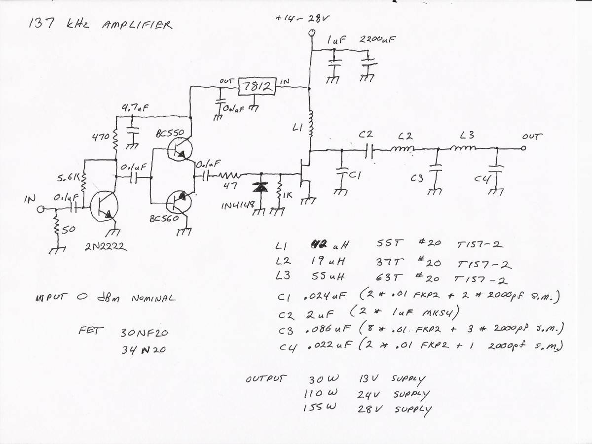
Schematic of the completed amplifier
Initially I used T106-2 cores for the inductors but in order to fit the required number of turns I had to use 24 AWG wire. Heating of the wire was excessive but otherwise the amplifier was showing a lot of promise. I decided to bite the bullet and order some T157-2 cores which would allow using 20 AWG wire. Note: heating of the wire in these inductors was not a surprise. My 630 meter unit does the same, as do several built by others. In the final design, it is possible to run high duty cycle at 100 watts output without a problem. For higher power I recommend a small fan blowing air across L1 and L2. It would probably be OK without the fan but I prefer to err on the side of caution. Capacitors C1 through C4 are made by connecting smaller values in parallel. I had a bunch of .01 uF 630 volt WIMA FKP2 capacitors and some 2000 pf 500 volt silver mica capacitors. These were the only two values needed when using the proper combination in parallel. The DC blocking capacitor is 2 uF, comprised of two 1 uF WIMA MKS4 capacitors in parallel. Initially I used a single 1 uF as in the 630 meter version but I found it was heating up slightly. Going to two of them in parallel resulted in no detectable heating.
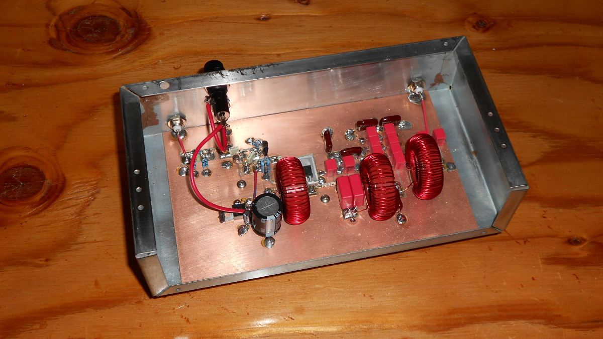
The 22200 meter “junk box” amplifier
Construction is similar to the 630 meter amplifier discussed in an earlier post. “islands” were made by grinding away some foil from double sided FR4 material with a rotary tool and diamond bit. The finished amplifier can be driven with one milliwatt (0 dBm), like its 630 meter counterpart. Power output is similar. I measured in excess of 30 watts with a 13 volt supply, 110 watts with 24 volts, and 155 watts with 28 volts. In all cases, efficiency is 87 to 88 per cent. These figures hold over a range of 134 to 140 kHz. Outside that range it beings to roll off rapidly. I have been running mine for the past couple of nights at 28 volts and it seems fine. In the interest of disclosure I did have one FET die during testing but I had not been watching the antenna matching closely enough. Temperatures plummeted from the mid forties to the high single digits during that night of operation, causing the antenna resistance to drop sharply. This caused power output to soar above 200 watts before the FET finally gave up at 3:30 in the morning. I do not consider this a fault of the amplifier. Knowing how 2200 meter antennas are, the operator should have been watching more closely!
Update March 7, 2018: The amplifier has been running perfectly with no additional FET deaths. For more than a week I have been transmitting a combination of WSPR-15 (a good test for any amplifier) and WSPR-2 at 150+ watts output.
Update March 10, 2018: I cranked the voltage up to 30V and have been running the amp at 175 watts output for three nights with high duty cycle WSPR-15 and WSPR-2.
Pingback: Update on ‘A Low Drive 2200 Meter Amplifier’ | N1BUG Adventures in Radio