I have a passion for radio, but it goes deeper than a hobby for me. As I continually struggle to maintain my relative independence amid the challenges of some very frustrating and debilitating challenges, it is a survival tool. To that end it is important enough to be among the highest priorities in life. Thus when misfortune struck I put much on the line to recover.
Over the past several years, with sacrifices on my part combined with generous contributions from fellow hams I have been on a station building spree. I got back into VHF/UHF weak signal work, greatly improved my HF antennas, and for some time was heavily into experimenting and attempting to work DX on 2200 meters. Things were going very well but all of that changed one winter night in December, 2020. We had a wet, sticky snowstorm that night. All of my wire and yagi antennas were heavily burdened with snow. At some point the strain was too much for the 2200m T antenna that was suspended between my two 100 foot Rohn 25 towers. It broke at one end and fell. The sudden reduction in side loads on the towers caused them to move slightly. With the burden of extreme weight of the snow, this caused significant, but fortunately not catastrophic damage. Some yagi elements were bent, traps damaged, coax cables damaged, masts bent just enough to bind, and one Rohn 25 top section was bent slightly, causing rotation to be extremely impaired on that one. All of the antennas from both towers were going to have to come down for repairs to themselves and the towers.
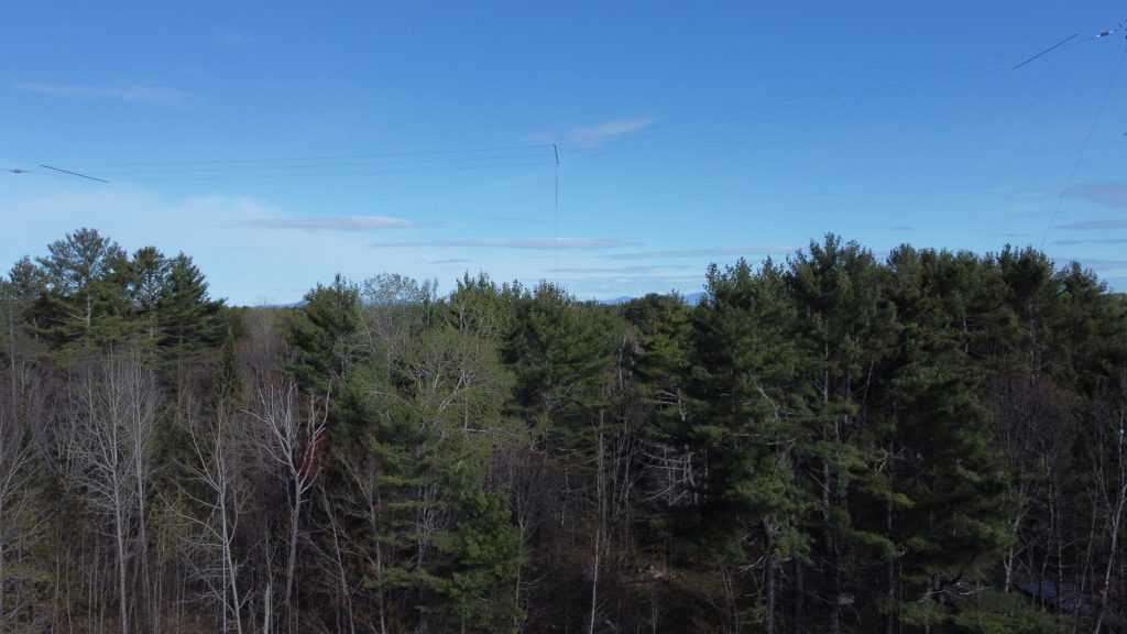
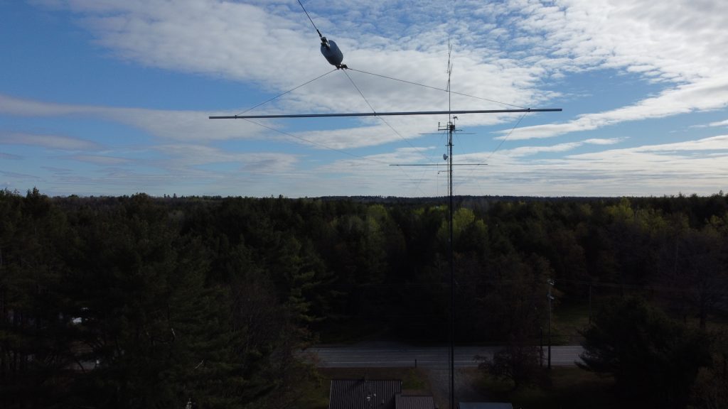
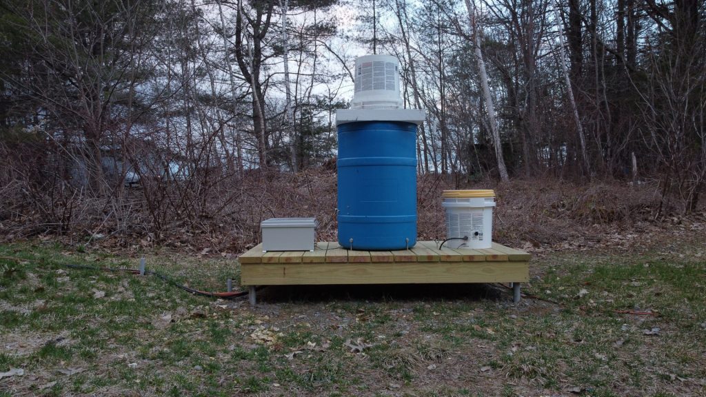
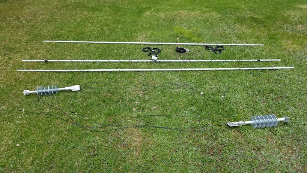
There are no photos of the aftermath or 2200m antenna laying in the snow. I was too depressed that morning to want to document anything. I stabilized what I could and over the next several days foolishly repaired the 2200m antenna. That allowed me to continue LF operations until Spring but I knew those days were coming to an end. Assuming I was able to repair the towers and other antennas, I could never again risk a similar disaster.
The first challenge was how to finance repairs. If I chipped away at it with whatever I could manage to set aside from my income, recovery would take years. The other option was to see if I could get a loan, despite my fixed income falling below lender minimum guidelines. I was not doing so well since the loss of most radio activities. Under some gentle prompting from my health support team I decided to pursue a loan. Fate smiled upon me and I got the loan, a sum not less than a third of my annual income. It will take some time to pay that off but I was on my way to rebuilding!
It was going to be a big project for me. I do all antenna work alone. That means a lot of trips up and down the towers, as I have no one on the ground to do anything and must often make several trips up for simple tasks. There were complicating factors going into this. One was that several months earlier we lost a local ham and professional tower worker whom I had known for 40 years. He died in a fall from a tower. To be honest that really shook me up and I had some difficulty with climbing early on in this project because of it. I was at least 40 pounds overweight which compounds that darn gravity thing! But I was going to rebuild or perish in the attempt! Lastly there are always days that I am unable to work or be outside, and that has been greatly compounded by a neighborhood situation which has had several of us making complaints. It was very difficult this year to find times that I could do anything at all. I often started around 2:00 AM and finished work shortly after dawn. These same factors make it impossible to schedule work sessions even when volunteers might be available. Under current conditions I either do antenna work alone or it won’t happen at all. I don’t know how many years I will be able to continue this, so I am making the most of it while I can!
First there were preparations and getting antennas down from the more heavily damaged tower. The 2200m antenna was taken down for the final time, a very sad day since that extremely challenging band had been of great benefit to me. I miss it every day. Some trees that had rather quickly grown up along the path of my tram line were cut, and the tram line was hauled up into place.
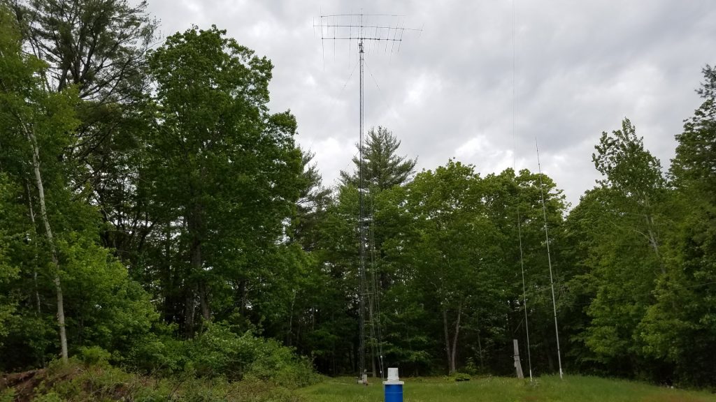
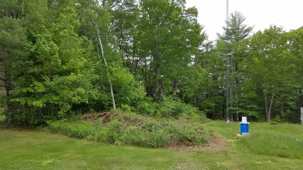
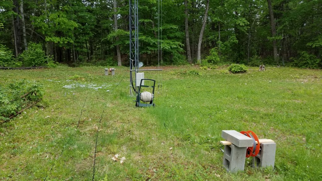
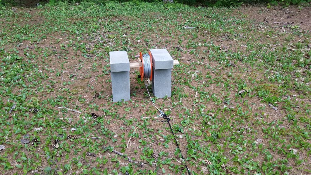
Special tramming operations needed to be carried out for the 6 and 2 meter antennas in order to get them past the elements of the TH11DX. It might have made more sense to remove the TH11DX first, but this was early in the season when I was very nervous climbing. To be honest, this was a mind game. I needed to see the big expanse of the TH11DX below my feet as I stood on a mast step to reach the upper antennas, or I would never get myself up there! I will argue that one should not climb if experiencing such discomfort and having to play such mind games but this was do or die for me. I was willing to take the risk of pushing myself into uncomfortable situations. In order to solve this clearance problem, the tram line was run horizontally from the mast over to the top of the other tower where it was joined to a rope running through a pulley down to a hand winch at the base of the tower. This allowed the VHF antennas to leave the tower going out horizontally, then to be lowered to the ground by letting out rope from the winch.
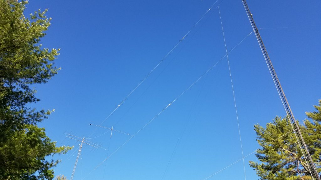
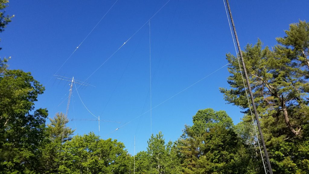
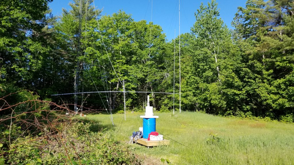
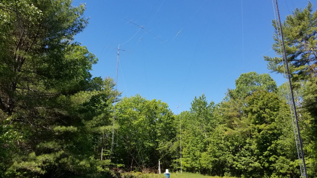
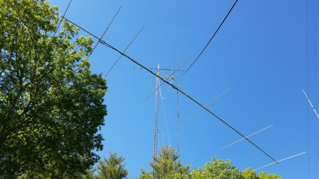
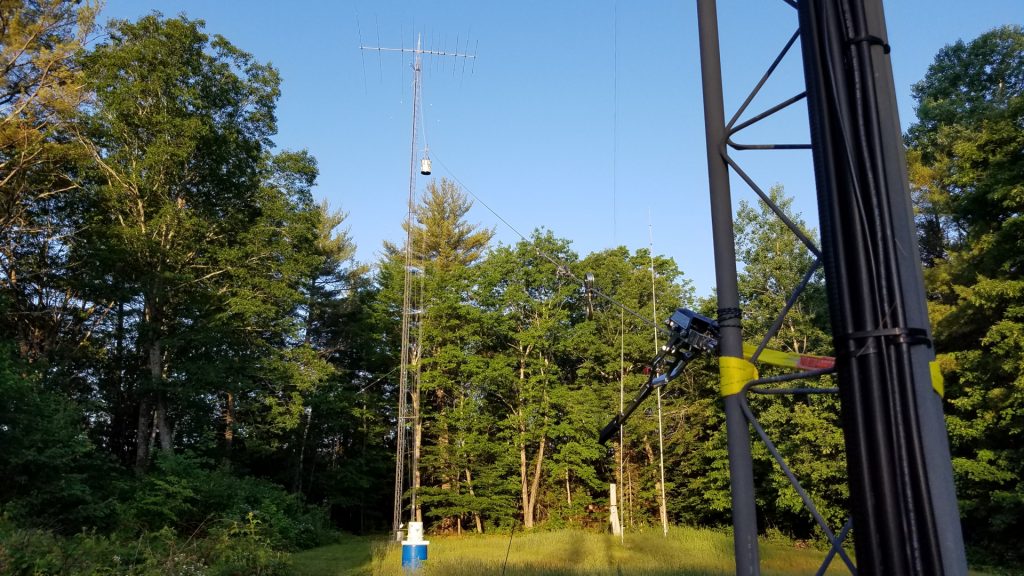
With the smaller antennas down it was time to tackle the TH11DX. For this, the tram was rigged in a somewhat more conventional manner, now going from the top of the mast down to a few feet above ground on the other tower. After the nearly 100 pound antenna was at ground level, I learned that I need to eat more Wheaties or something! It was a struggle to pick it up, walk over to the short Rohn 45 tower with it, and mount it at shoulder level on that tower where it would remain until everything was ready for it to go back up.
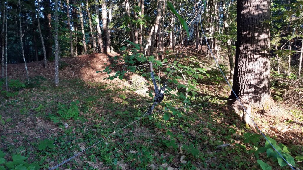
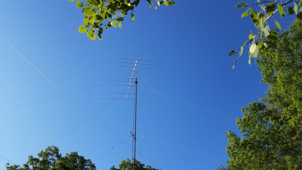
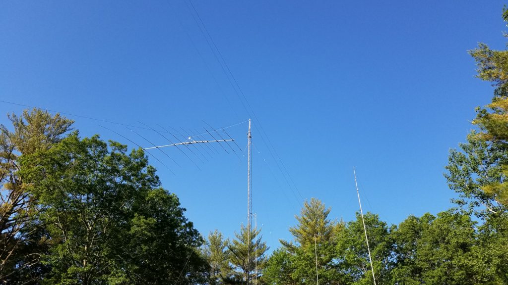
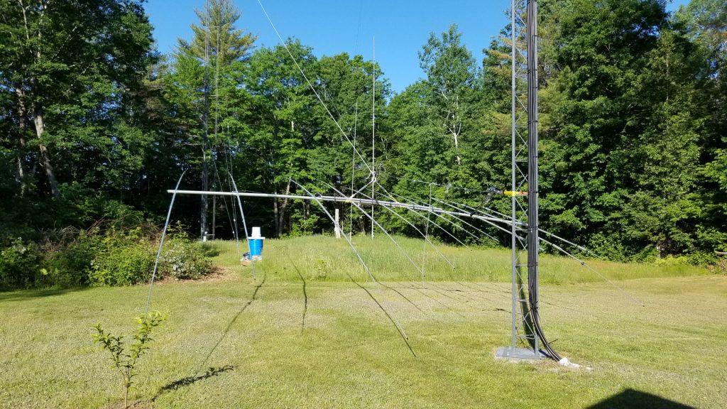
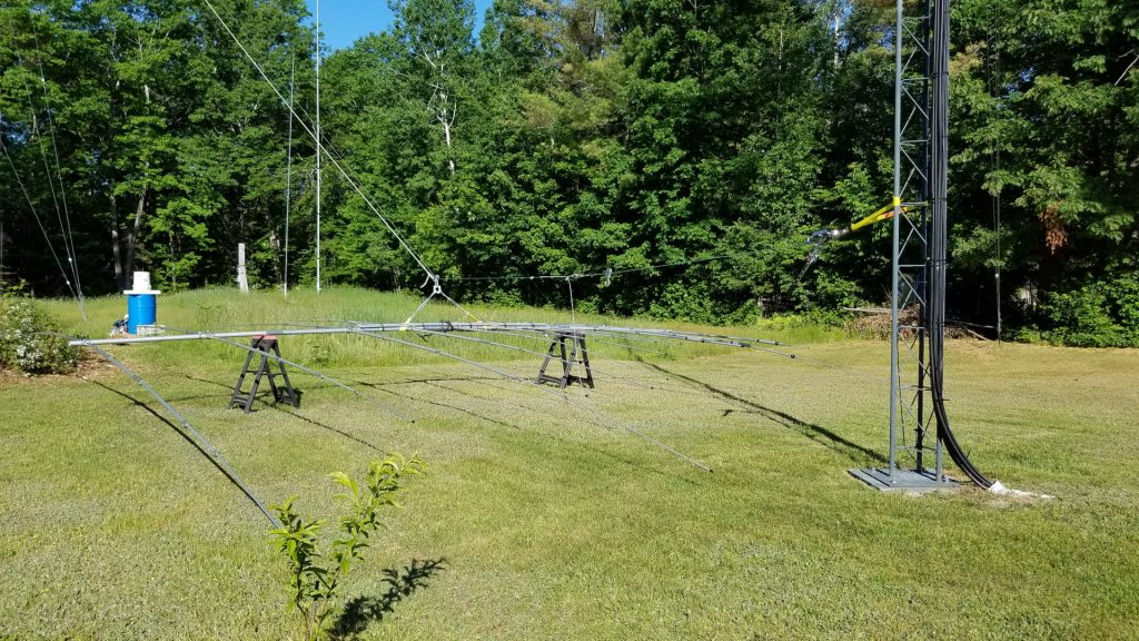
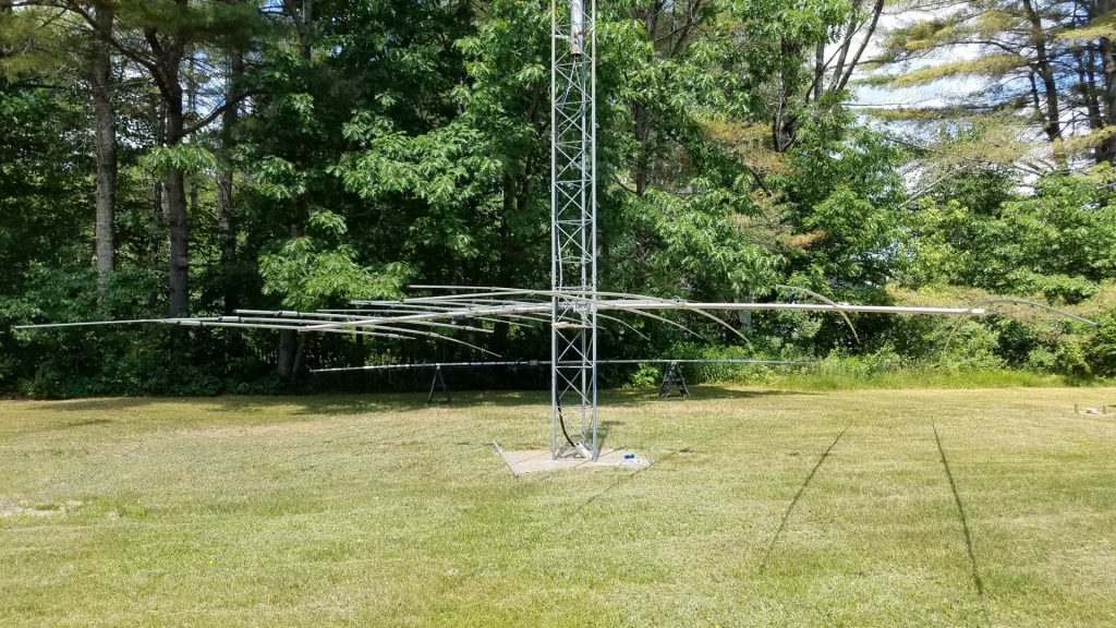
I was not doing so well after months of not having radio which I rely on for stress management, and really wanted to be active for sporadic E season and the Perseids meteor shower. I decided to repair and mechanically upgrade the 2m antenna and then temporarily put it on the other tower, below the 222 and 432 MHz antennas.
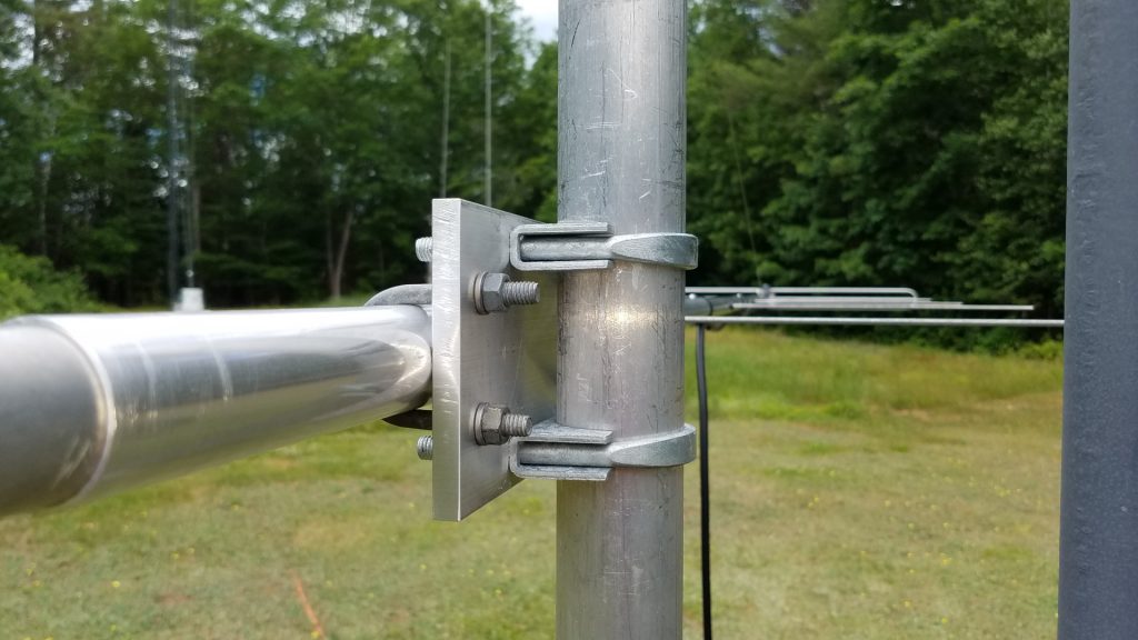
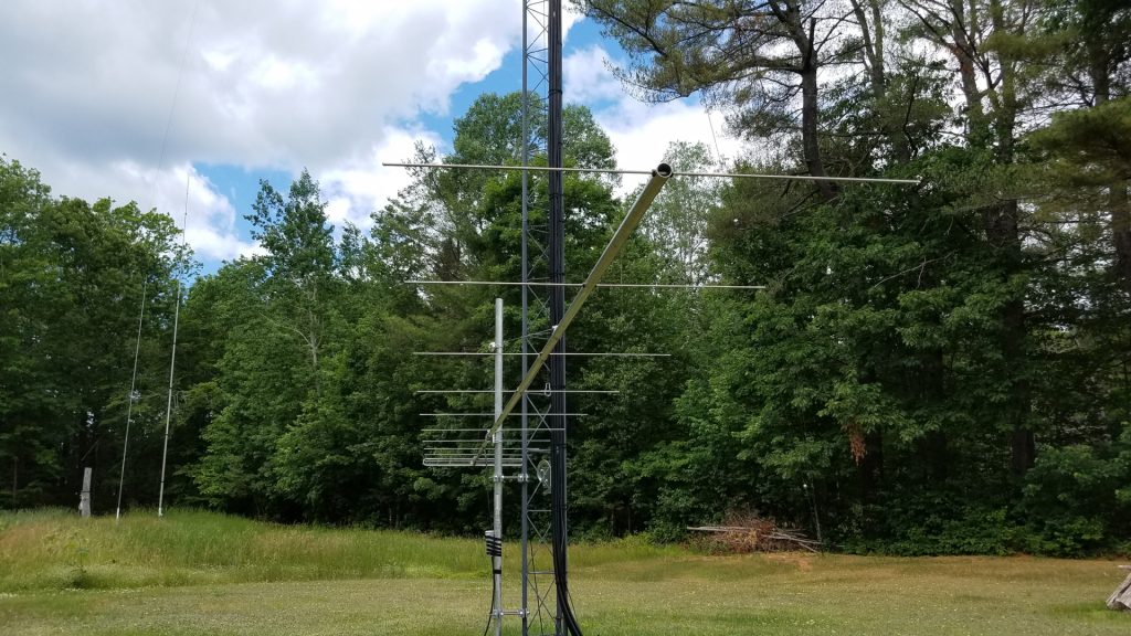
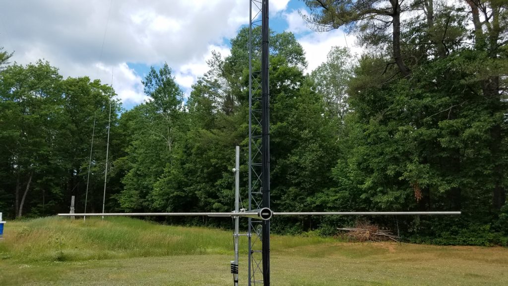
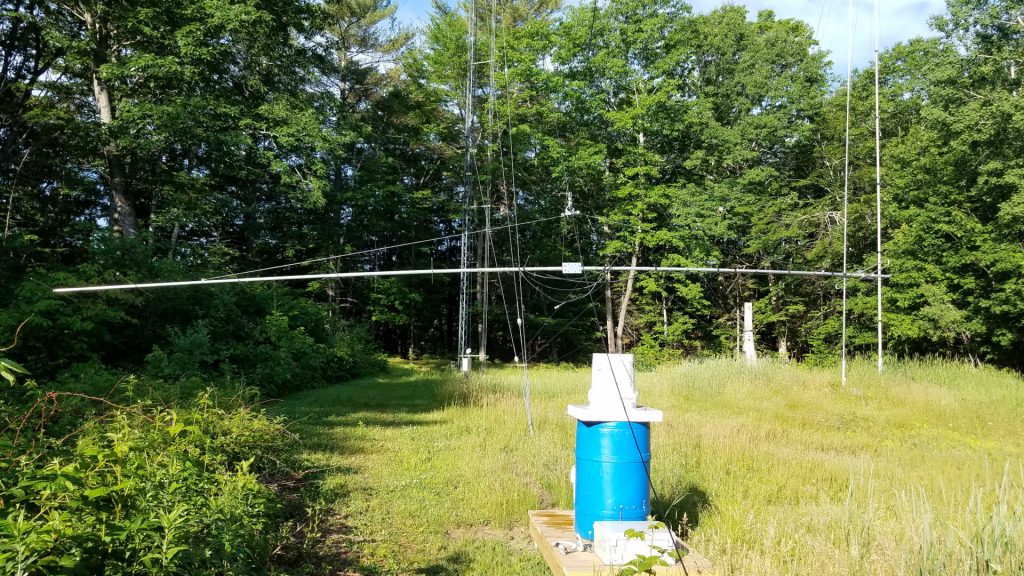
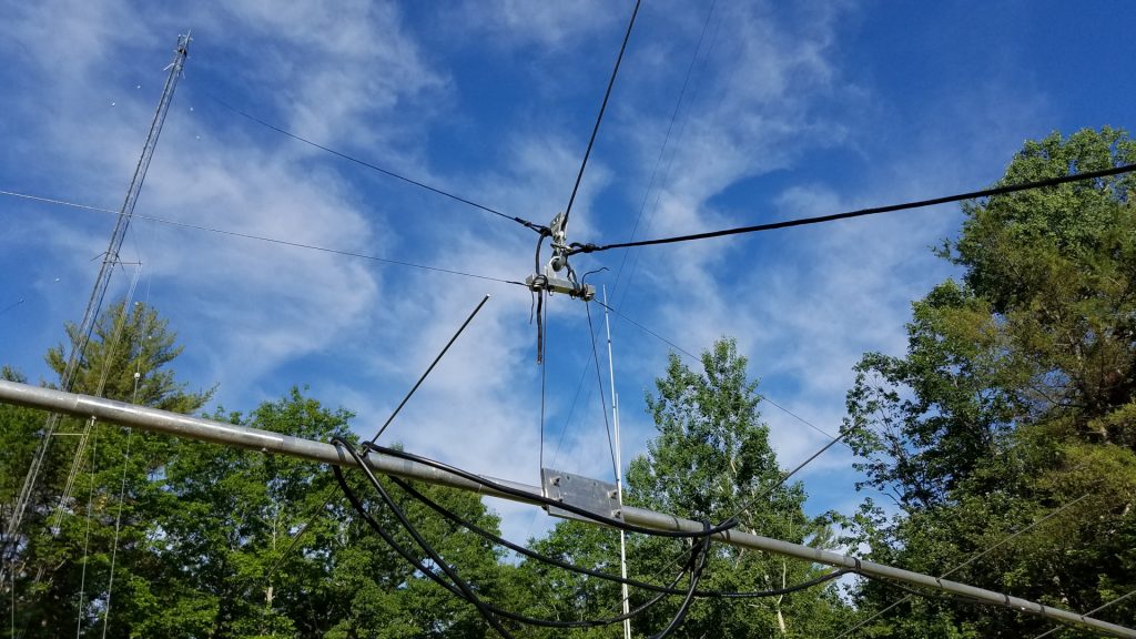
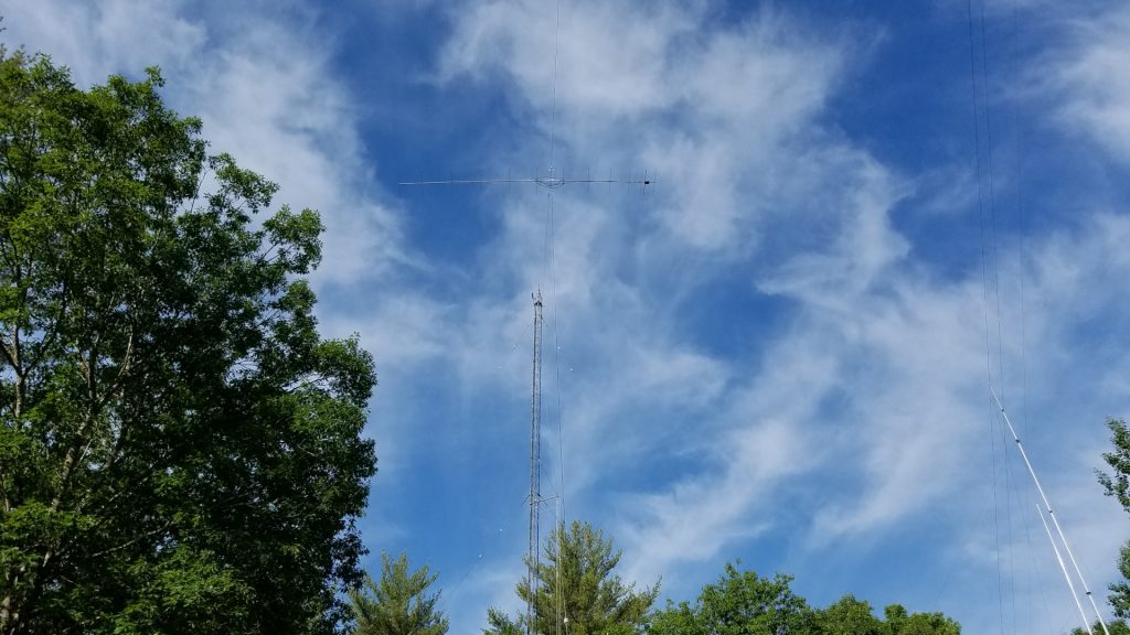
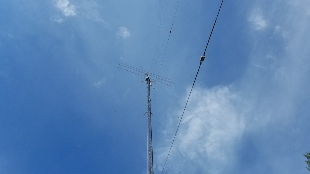
I caught a couple of massive E skip openings on 2 meters and did very well in the Perseids on both 2 meters and 222. I was glad I took this step of putting the 2 meter antenna up in a temporary fashion. After the Perseids it was time to remove all antennas from the northeast tower and get to work on the new VHF/UHF stack there.
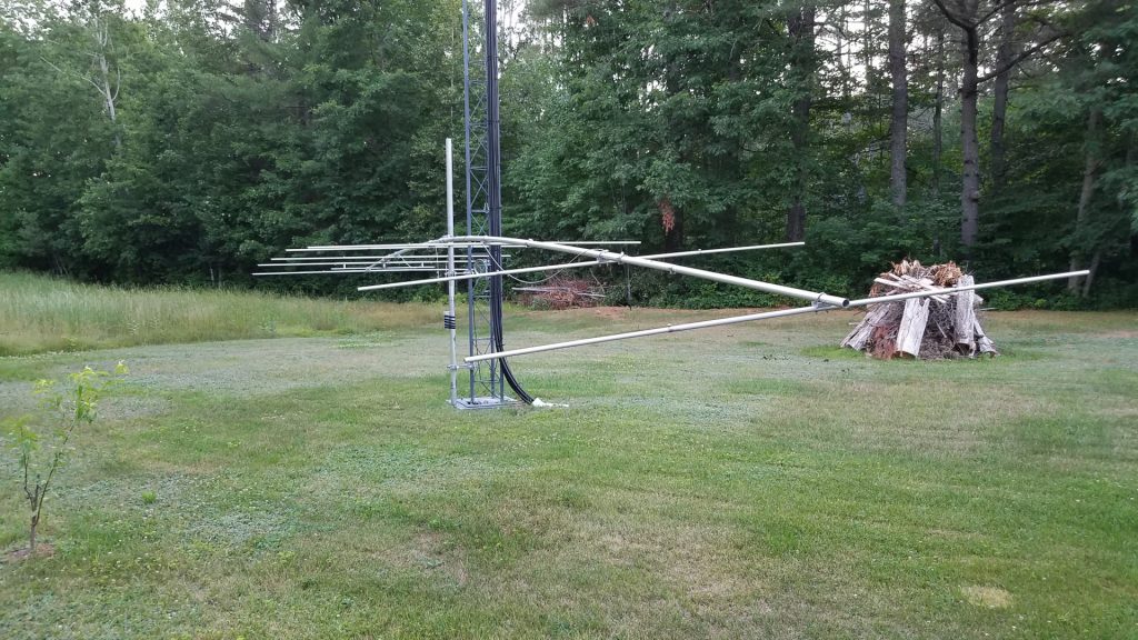
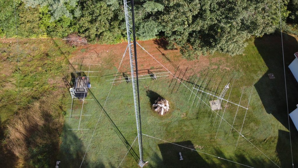
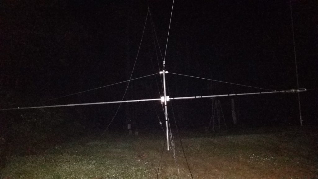
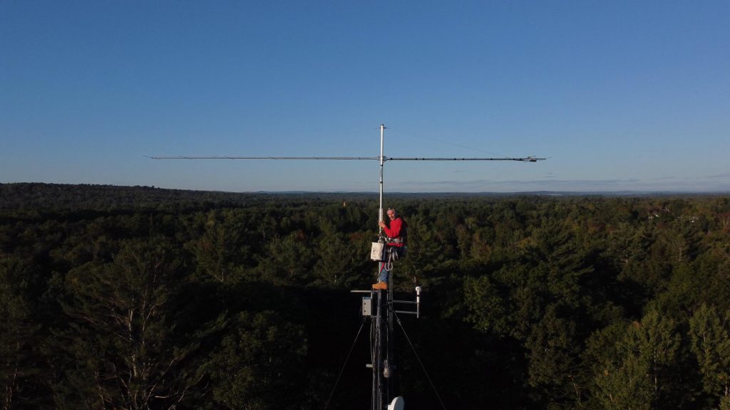
I had a setback after getting 2m, 222 and 432 yagis up and mounted on the mast. While raising the mast to final position in preparation for rotator installation and adding the 6m antenna, the three coax cables got caught on the tower and damaged. I had to take all three antennas down and replace the coax a second time!
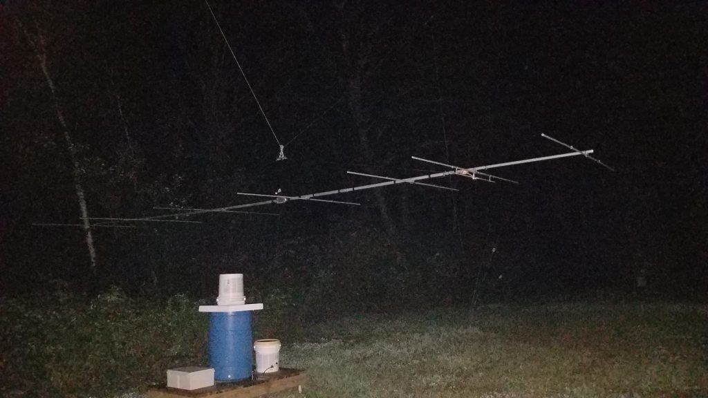
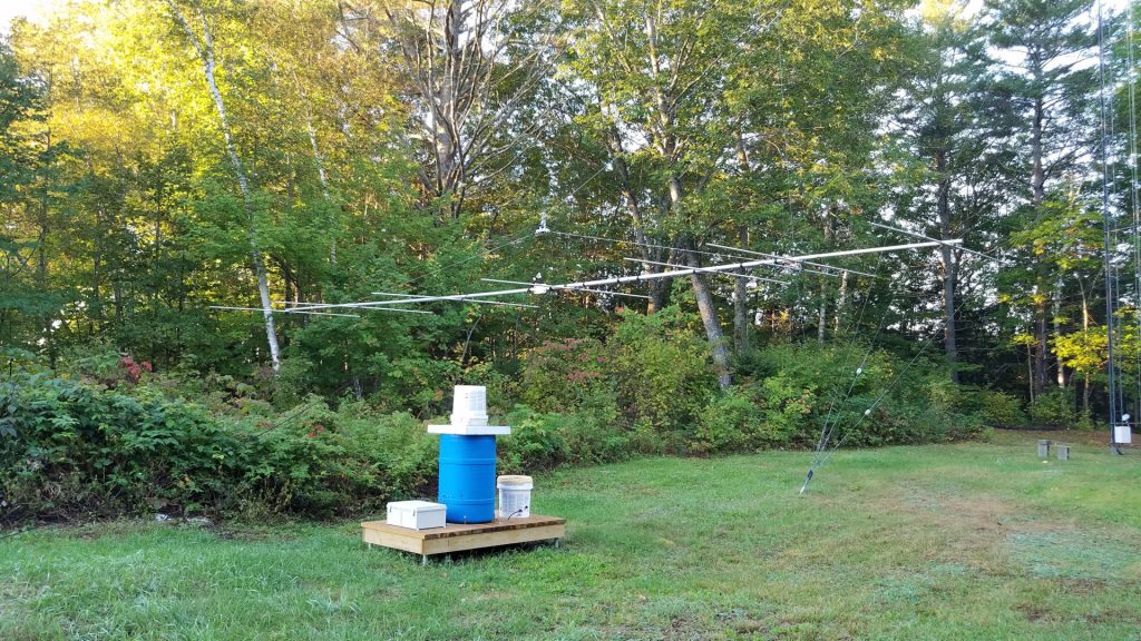
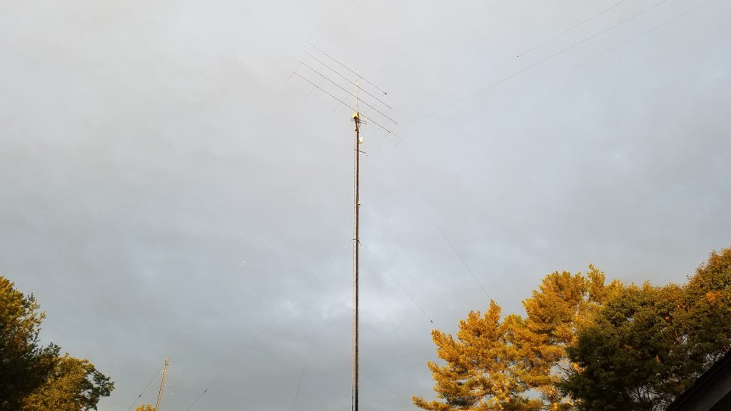
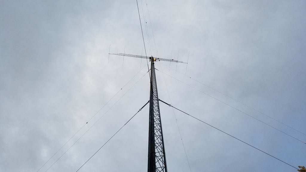
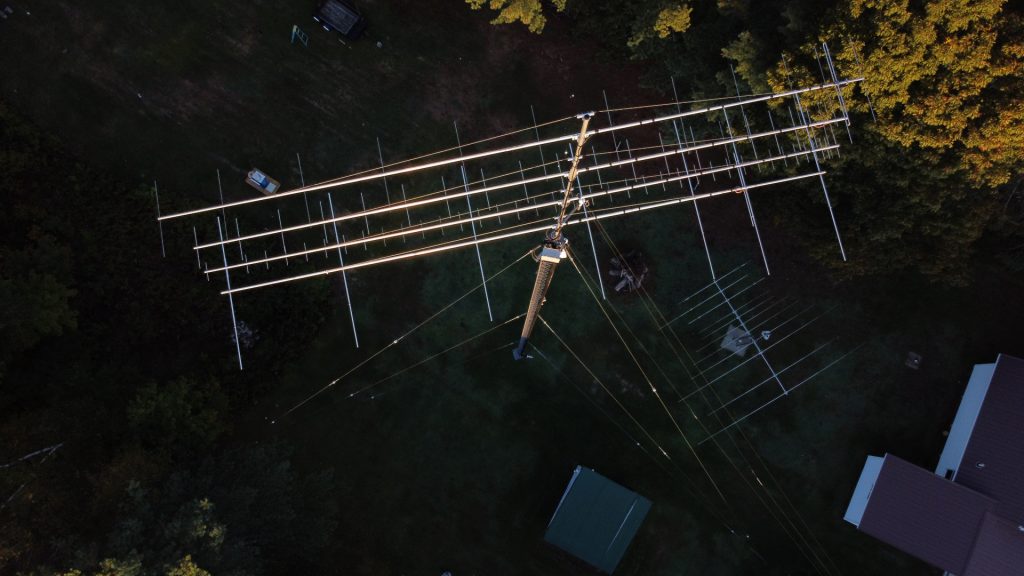
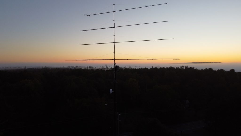
Now it was time to get to work on repairing the southwest tower. I added a temporary set of guys 10 feet down from the top and lowered the regular top set. The first challenge was removing the old mast and rotator. I had to hammer things apart and beat the mast out of the Rohn 25 pointy top section with a sledge hammer! That’s a lot of fun 100 feet in the air. Replacing the tower top section required some special rigging. I had LDF5-50A, 0.84″ CATV line and rotor cable all running up the inside of that tower! There was no way I was going to dig those buried cables up and pull them out of the tower if I didn’t have to. I couldn’t replace the top section using a standard 12 foot gin pole because it lacked sufficient height to lift a tower section straight up and free of the cables. I made a long gin pole out of a 20 foot section of 2 inch 6061 schedule 80 aluminum pipe and mounted it across two tower legs with pieces of 2 inch by 2 inch by 1/4 inch thick galvanized steel angle. As with all tower section lifts, I used a counterweight on the rope below the gin pole to take most of the weight of the section. I attached a length of 1.5 inch OD 1/8″ wall aluminum tube to the braces of the tower top section to act as a lever/handle so I could push it up and off the cables. This worked out pretty well, and the new stop section was rigged the same way for going up and over the cables. In the interim since the tower was first installed I had managed to acquire a 25AG4 flat top section which is far more desirable than the pointy top. After getting the top section replaced, the permanent guys were put back in place and the temporary set removed.
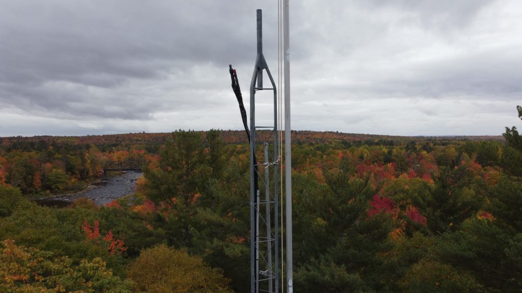
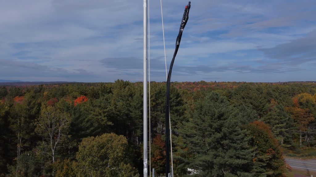
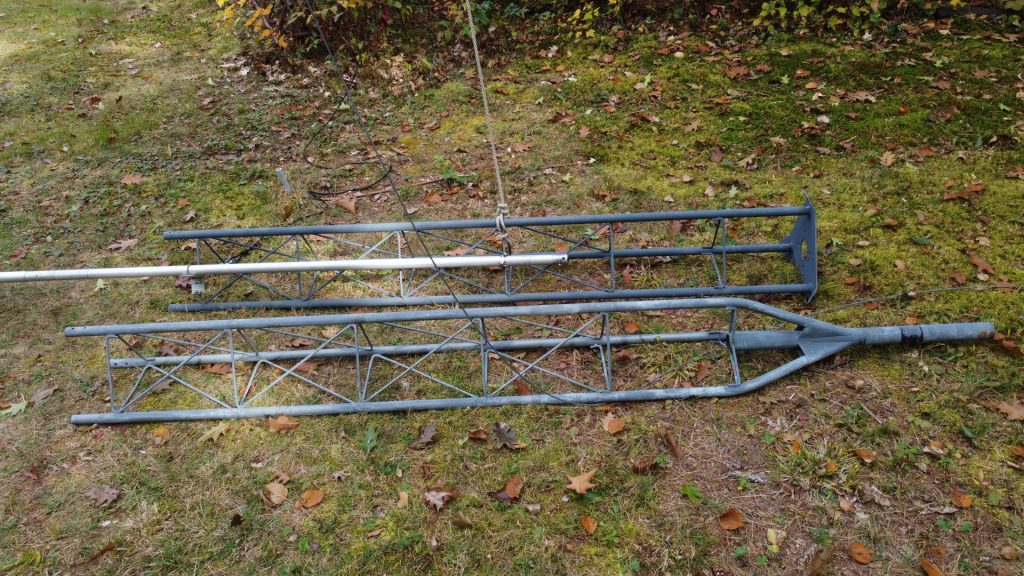
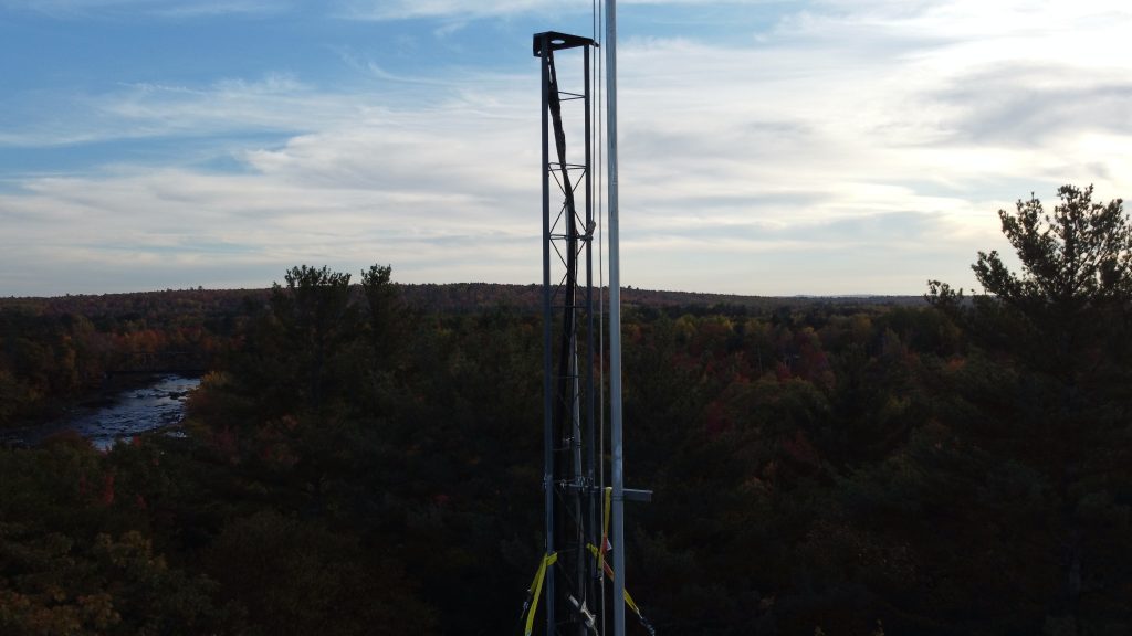
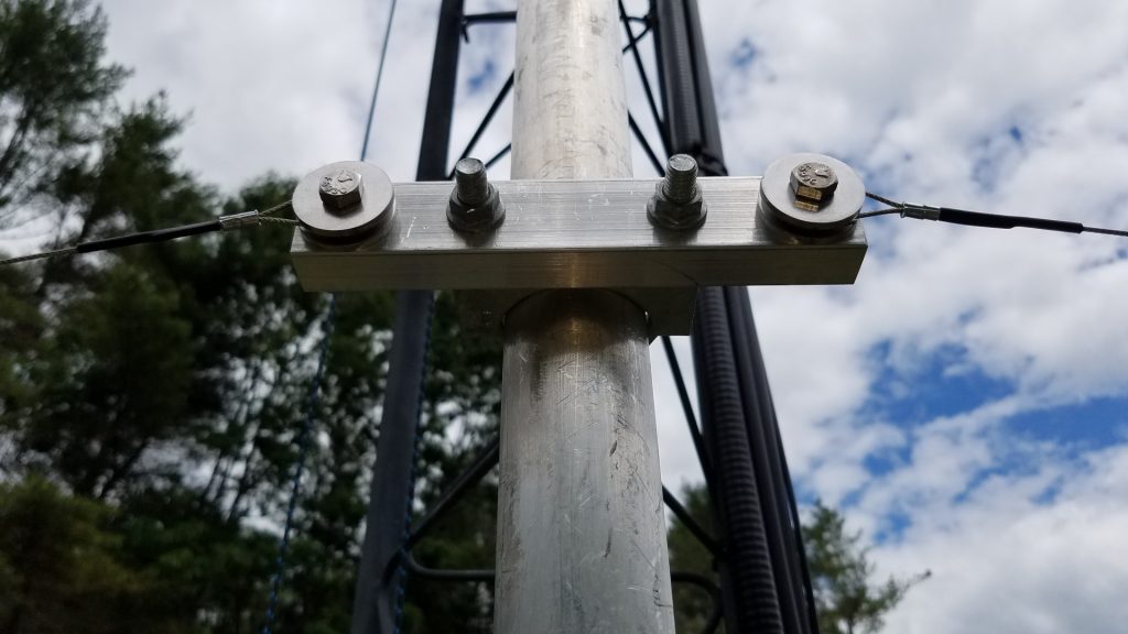
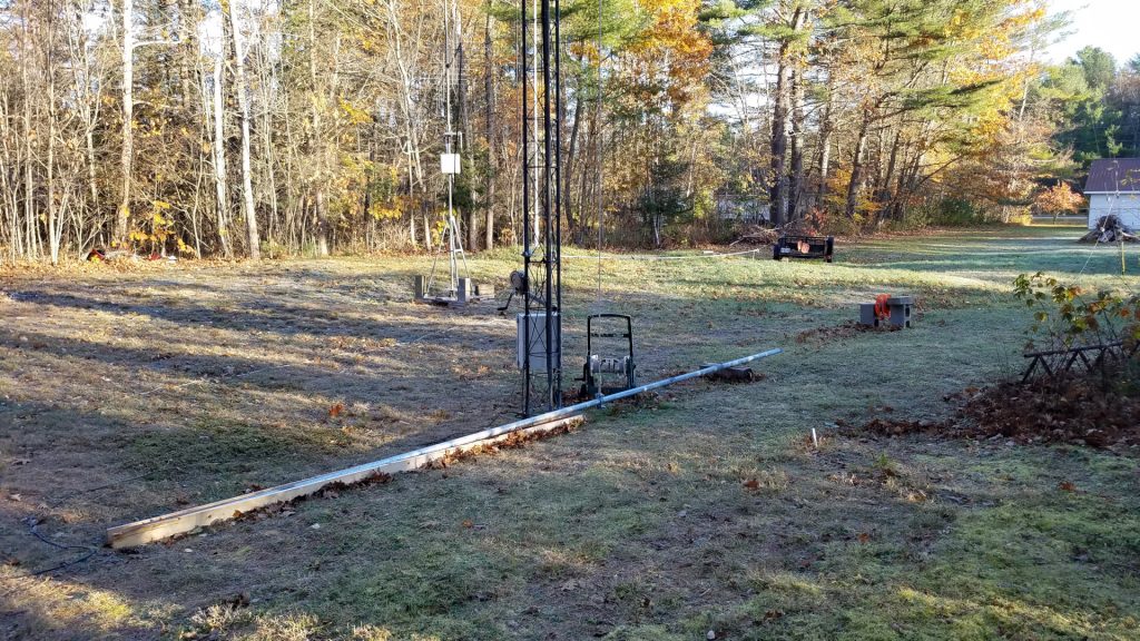
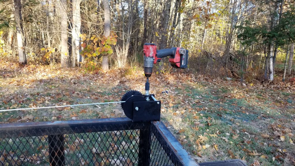
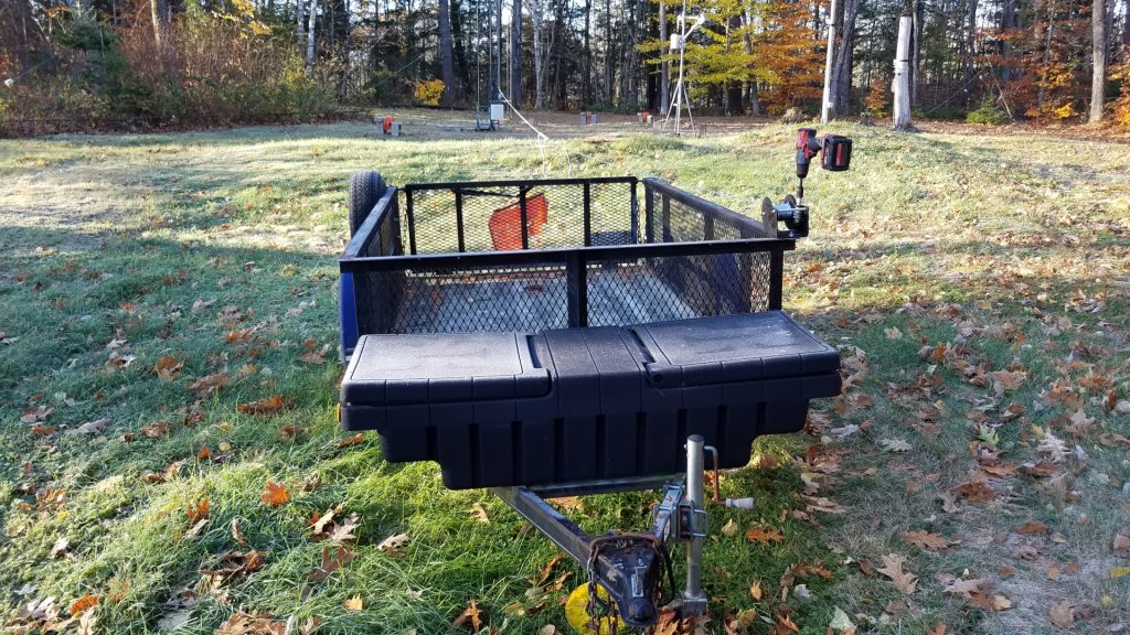
I mounted a proper thrust bearing on the tower top, and put an accessory shelf at the bottom of the 25AG4 for the rotator. In between another accessory shelf was fitted with a centering bearing made of Acetal plastic. I used DX Engineering shelves and I must say they are far better than Rohn shelves! The top bearing is also a DX Engineering product. The next task was getting the new 22 foot long 4130 chromoly mast into place. Weighing 125 pounds it was going to be a challenge for me. I once again used the long gin pole to good advantage. Instead of using counterweights, I rigged a worm gear winch to haul the thing up. This was the one thing I did have help with for about 10 minutes. I hauled the mast up until the top of it was inches below the top of the tower, then had a helper run the winch while I was on the tower for the last 23 feet of lift and dropping the mast into the tower.
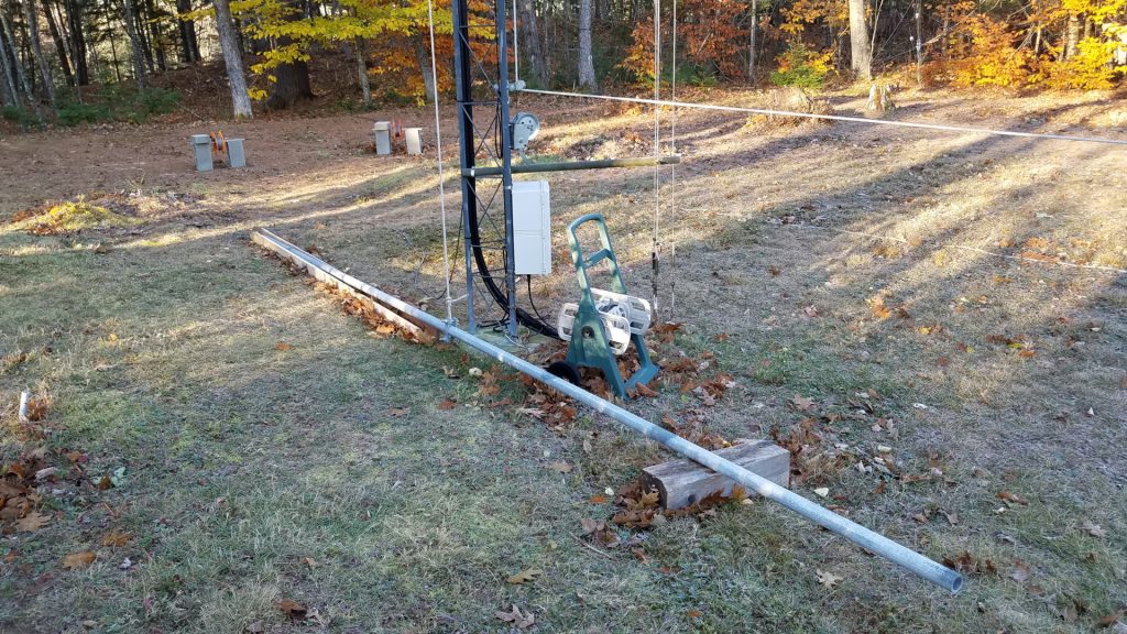
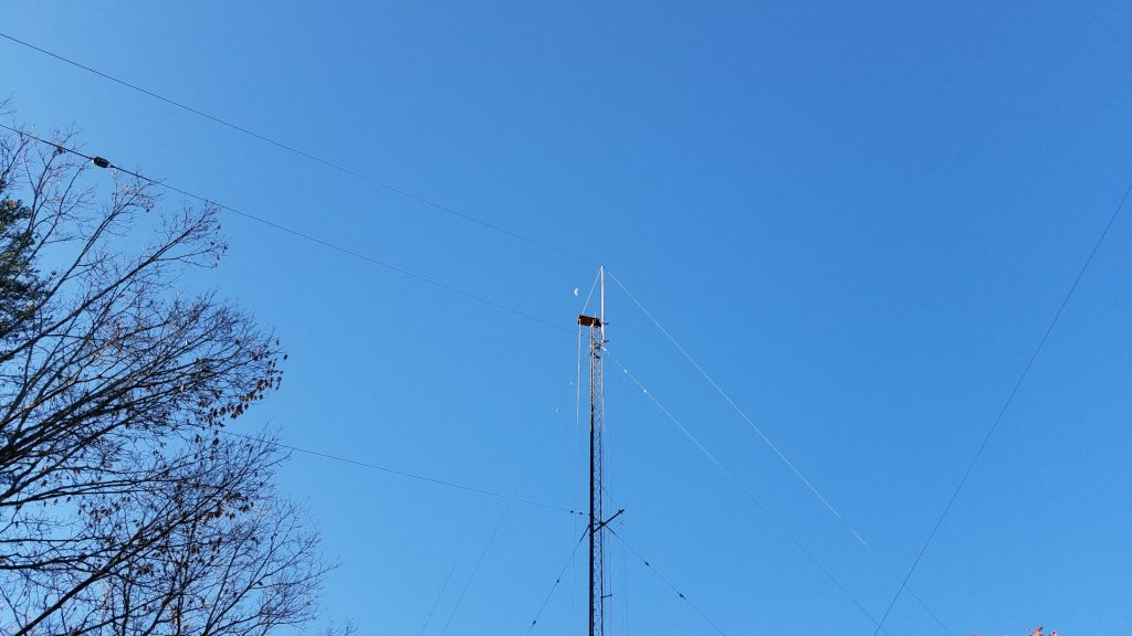
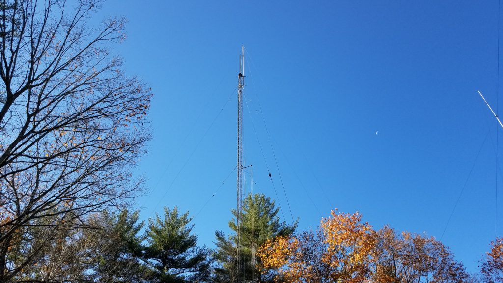
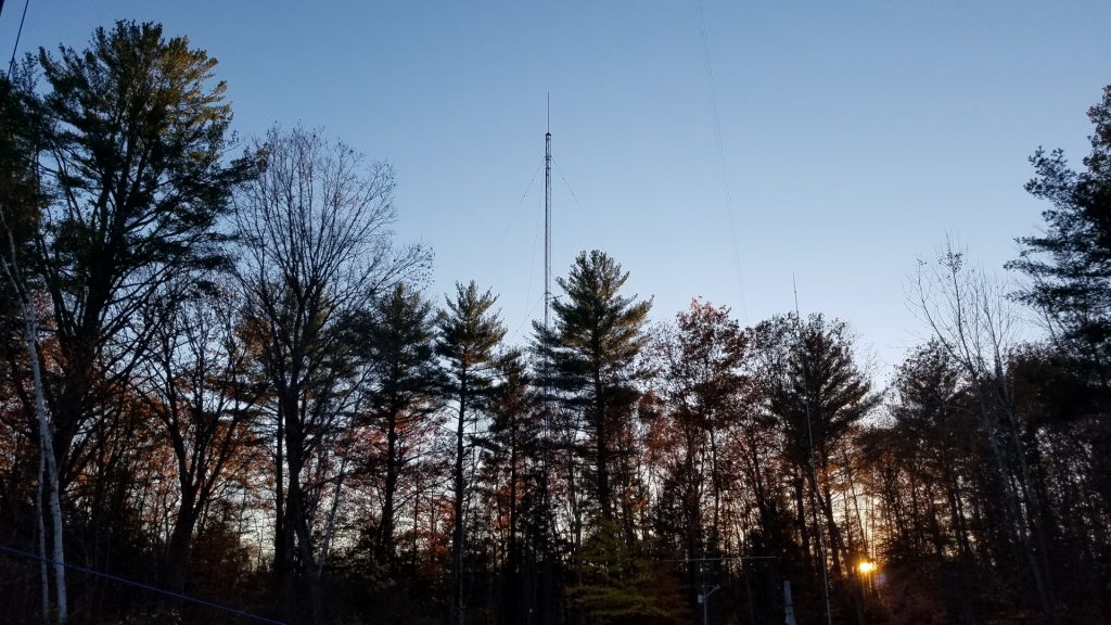
I did manage to sneak an upgrade into the rebuilding effort. I acquired an OptiBeam OB1-4030 rotatable dipole to replace my 40 and 30 meter inverted V antennas that always seemed to have me struggling to work the DX, let alone struggling for contest QSOs. I had been hearing that a dipole beats an inverted V at the same height, so I decided to try this after two failed attempts at home brewing a two band rotatable dipole in recent years. Besides, I was on a campaign to eliminate as many wire antennas hanging off the towers as possible. Skipping ahead, it turns out the improvement is nothing short of incredible! My 40 meter inverted V was at 104 feet, 30m at about 90 feet. The OB1-4030 is at 108 feet on the other tower 145 feet away. I was able to leave the old antennas in place for a while to make comparisons. The OptiBeam beat the inverted V antennas by margins ranging from 5 dB to more than 35 dB depending on the station and time of day! Every time! I have done extensive comparison using the Reverse Beacon Network. I have also experimented with calling DX stations many times with the old antenna and then the new one. Often they continue to CQ while I call time and again with the old antenna but I work them on the first or second call with the new one. I can work DX I never could before and get a much better run going in a contest. This is just amazing! Most of the time I found I no longer needed Beverages for receiving on 40 meters. The exception being during multipath conditions where the CW was difficult to copy. Then the Beverages still provide advantage.
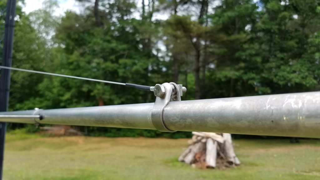
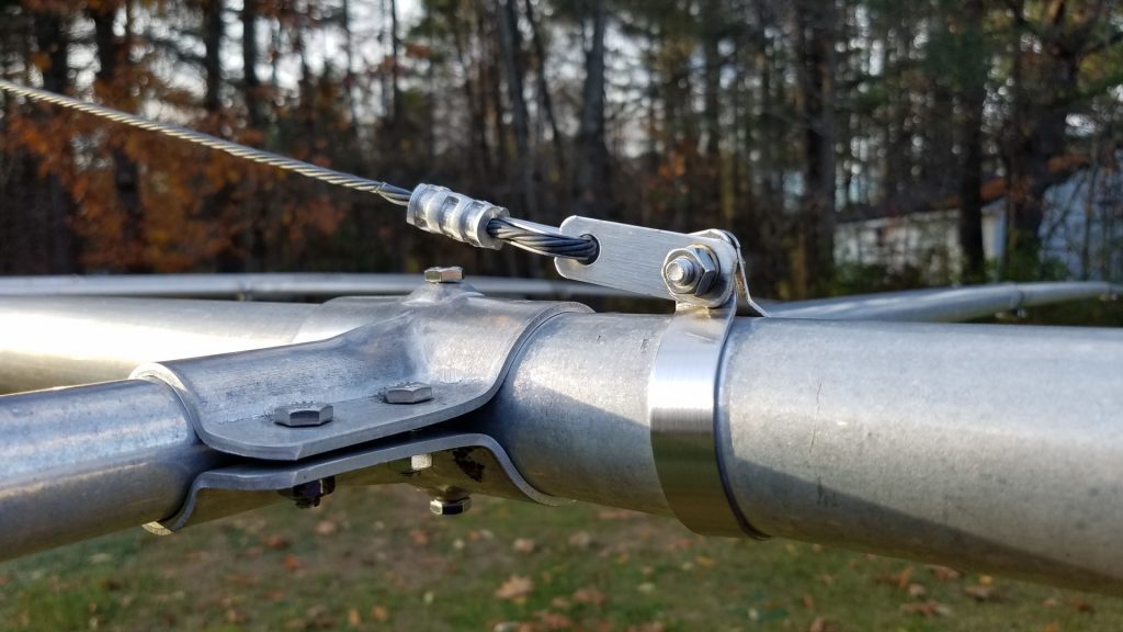
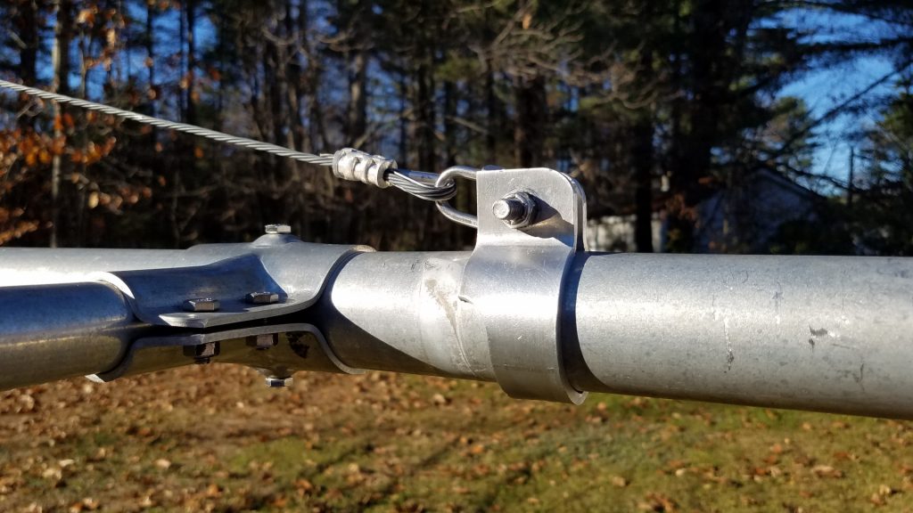
The TH11DX needed more attention than any other antenna. The traps were taken apart, modified with additional screws to reduce wobble, shattered trap caps were replaced and covered with 3 layers of Super 88 vinyl tape, element tips were straightened, coax replaced and the ridiculously inadequate boom truss hardware was replaced with something more reasonable.
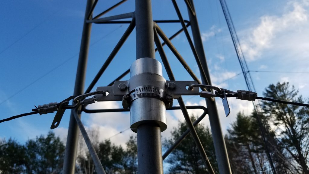
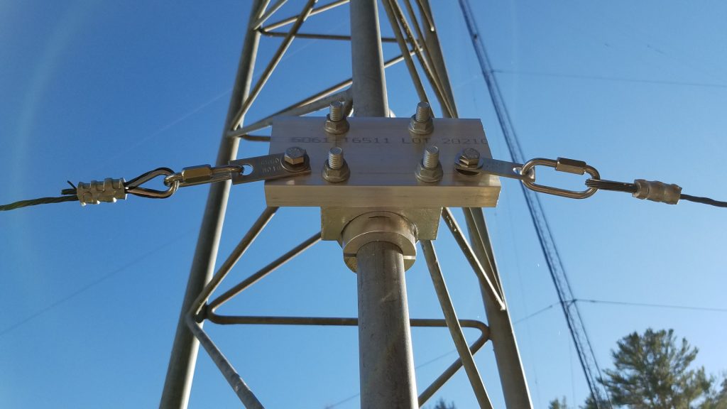
Six years ago I struggled to tram the TH11DX up working alone. I did it by hand, wrapping the pull rope around my waist, leaning back and walking backward for the pull. I was pleased to see that now, at the age of 58 I can still do it, and somewhat easier than the first time. That’s odd but I’m not complaining!
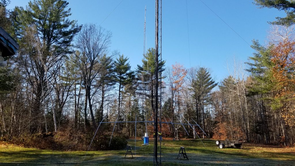
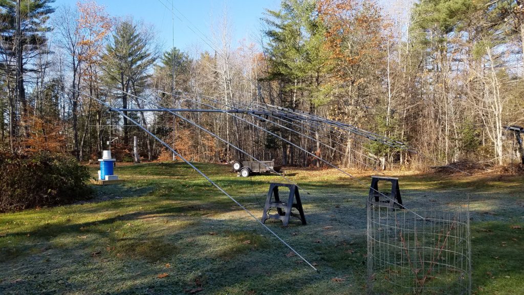
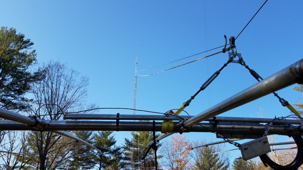
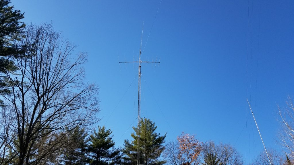
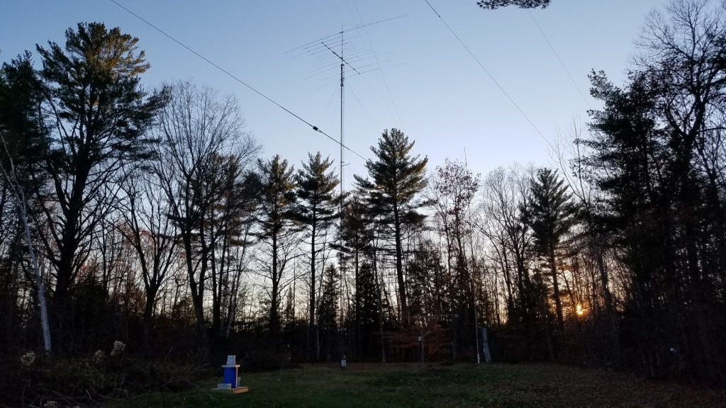
I was concerned about interaction between the TH11DX on 15 meters and the OB1-4030. I had chosen to start without a 90 degree offset to see what happened. I see no detrimental affect. The TH11DX still has a good pattern on 15 meters (and all other bands), SWR is fine, and from what I can tell it is working as well as it has all along. I got away with it!
The last of this work was completed with snow on the ground. As of December 2021 I still have some work to do on low band receive antennas which have somehow managed to develop issues during the a period of disuse. Other than that, all damage has been repaired. 160 meters through 70 cm are back up and running. The loan was a necessary evil but unfortunately it means very limited new projects for a while. During the course of this project, May through December, with great effort and force of will, I was able to lose 40 pounds. By the end of the project my comfort climbing was as good or better than it has ever been.
