Category Archives: MF & LF

Mowable Temporary Cables

What? Mowable cables? That doesn’t make any sense! Let me explain. Throughout my nearly four decades exploring radio, I have often had occasion to run a “temporary” cable to some antenna. Usually these end up laying on the ground where they quickly become a nuisance, having to be moved every time the grass needs to be cut. This often continues for some time. After all, in a ham radio sense the definition of temporary is “anything expected to be in service for less than the life expectancy of the operator”. About year ago I had a sudden explosion of “temporary” cables. I needed to run coax and a variometer control cable to my new 2200 and 630 meter transmitting antenna, as well as coax to a receiving antenna for those bands in another location. These were put down just after the last lawn mowing of the season, but were at risk of damage from the snowblower as I kept a path cleared to the transmitting antenna during the winter. This summer they have been a constant source of irritation as I had to move them every time I mowed the grass.

Since I still can’t afford good coax and conduit to do this job in a permanent (meaning less irritating) fashion, something had to be done. One obvious solution is to dig a shallow trench and lay the cable in it — with our without burying afterward. This tends to be a lot of work and it’s messy, disturbing the grass (uh, I mean the weeds) and leaving dirt strewn all over. I was looking for a cleaner and, hopefully, easier method. One morning about 2 AM it came to me. I sat bolt upright in bed, sending Boo (the cat, who had been asleep on my chest) fleeing for cover. Who said you had to dig a trench? I have soft, sandy soil. Surely one could press a trench into the ground without the mess. It just might be easier, too. The following series of pictures depict the process, which worked very well.

Step One: Mark a line. Drive in stakes at each end and at any locations along the run where a bend is required. Run string (or small wire) from end to end, then spray paint a line on the ground along it.

Details of the string (wire) and painted line at a bend point.

Step Two: Hammer a slot into the ground. I used an 8″ x 8″ dirt tamper and a 10″ length of 1.6″ OD steel pipe. Lay the pipe on the painted line and hammer it in until its top is flush with the surface of the soil. In my soil this takes two to three blows, and the flat plate of the tamper makes it easy to know when you’ve reached the correct depth. This photo shows the pipe in place before being driven into the soil.

Here is a photo showing results after the pipe has been driven flush with the soil. To continue I simply pull out the pipe and move it forward 9 inches (just a bit less than the length of the pipe), then drive it into the soil again. The process moves along quite quickly.

Step Three: Lay the cable into the trench. I make 15 to 20 feet of trench at a time, then lay cable into it, then do another section of trench.

The completed job. There is no messy strewing of dirt, the paint line has virtually vanished, and the cable can barely be seen if one is not standing very close to it or directly in line with it. The top o of the cable is 3/4″ to 1″ below grade, so it is out of danger from the mower. Of course it is still subject to damage from any number of things, but with temporary cable runs that is usually a fact of life.

First USA to Europe Amateur Radio 2200 Meter QSO

It was early morning on the 28th day of March, 2018. Most people were sound asleep but not me. I was in my ham shack, hands trembling, heart pounding as I typed a few letters and numbers into my logging program. I could barely breathe. I had just completed one of the most exciting QSOs of my nearly four decades chasing DX. This single QSO cost more money and time than any other I had ever made. It was a QSO with England. You may wonder what is so exciting about that when any ham with five watts and a piece of wire can contact England from Maine. Well, this was special because we did it on the 2200 meter band. It was the first amateur radio USA to Europe QSO on what is, for us, a new band. This was no easy feat. It required months of station building and four nights just to complete the QSO. Some would call it a ridiculous folly and see no sense at all in it. But to me this is the true spirit of amateur radio, finding a way to communicate against the odds, adapting equipment and technique to accomplish the desired result. It is man and his machine against nature, determined to succeed under the most difficult circumstances.

The 2200 meter band allocation is 135.7 to 137.8 kilohertz in the long wave part of the radio spectrum known as LF or low frequency. In some ways this goes back to amateur radio’s early roots on 1750 meters, but it had been more than 100 years since U.S. amateurs were allowed to transmit in this part of the radio spectrum. These frequencies are not easy! Normal size antennas would be huge. A half wave dipole would be 3400 feet long; a quarter wave vertical towering to a height of 1700 feet. Natural and man made noise tend to be very high in this part of the radio spectrum and ionospheric propagation is feeble compared to the short waves. On top of that, we are only permitted to run one watt effective isotropic radiated power (EIRP). That is flea power compared to what we can use on most any of our higher frequency allocations! By comparison, when I was doing EME (moonbounce) on the two meter band I was legally running about 450,000 watts EIRP. But ham radio DXers who like a good challenge can be a very determined lot. The greater the challenge, the greater the reward.

I became interested in 2200 meters in late 2016 after the local club asked me to prepare a report on this and the 630 meter band, which were expected to soon be opened for amateur radio use in the U.S. At that time the only way to legally transmit on either band was to get a Part 5 FCC license under the experimental radio service. One could almost write one’s own ticket on power limits and frequency allocations but this wasn’t amateur radio. I did apply for and was granted a Part 5 license but never used it since FCC opened these new bands to amateurs just as I was getting a station put together. I found receiving on 630 meters to be relatively easy, if somewhat plagued by noise and available antennas. But 2200 meters was a very different thing. It took weeks of experimentation and testing to detect the first trace of signal on this band. Many weeks later after more trial and error I was rewarded with my first reception of a ham radio signal from Europe on the band when DC0DX appeared in my WSPR decodes. I confess it was then that I first started to dream of someday making a two way QSO across the Atlantic on long wave.

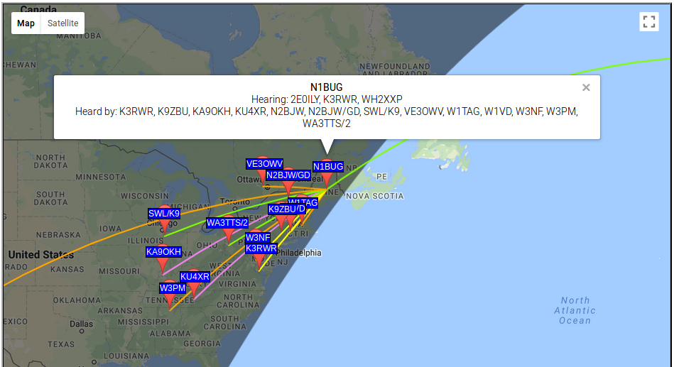
I thought I had plenty of time to build a station, since the FCC process on opening these bands had been dragging on for years. But in the Spring of 2017 the announcement came that we would get these new bands in a few months! Now the race was on. I frantically began building transmitting apparatus. I didn’t quite make it for opening day in October but I was on the band a few weeks later. Early amplifiers were plagued by budget shortfalls and poor performance. By mid February, 2018 I had managed to achieve 0.5 watt EIRP, just three decibels below the legal limit. The flood gates opened and to my amazement I started receiving numerous WSPR decodes from European stations. Wow!

I believed a two way trans-Atlantic QSO was in my future but was not sure when. I was eager for an attempt but still very much struggling with equipment and budget. I was hearing stations from Europe. Stations from Europe were hearing me. But for the most part, those who heard me did not have transmitting capability or not sufficient to reach across the Atlantic. The best bet would seem to be 2E0ILY. We had conducted tests earlier in the season and I could often copy his JT9 beacon. Chris could occasionally copy my WSPR signal but not at sufficient strength for JT9 to be viable. I knew there were ways to get it done, but this would take several nights. I was hesitant to ask anyone to commit such effort and time to a QSO.

As the relatively quiet season was drawing to an end I realized another season is never guaranteed for any number of reasons. I had given the matter considerable thought. There were no practical digital modes which would work with the low signal levels involved. Two old school modes came to mind: QRSS and DFCW. Both are very slow, trading time for weak signal detection capability. QRSS is extremely slow CW, so slow in fact that it can only be copied by reading it off a computer screen. In this case, a speed of QRSS60 would be best, meaning that each dot would be 60 seconds in duration. A dash is three times as long, just as in normal CW. This mode requires nothing special for equipment, as it uses on/off keying of a carrier and is fairly tolerant of frequency drift. But, the shortest element, the dot, sets the achievable signal to noise ratio. There is no advantage gained from the dashes being three times as long, so it is essentially time wasted. Time is valuable, as signal fading means you have a limited amount of time to copy the message. DFCW, or dual frequency CW is an offshoot of QRSS in which dots and dashes are the same length but sent on slightly different frequencies so that one may be differentiated from the other. This saves considerable time with no reduction in signal to noise ratio but requires more complex transmitter keying and reasonably tight frequency stability. In a typical DFCW60 transmission, the dot to dash frequency shift is a small fraction of a hertz. Transmitter and receiver drift must be held to less than this in order to avoid dot-dash ambiguity at the receiving end. It would take about an hour to send two call signs at DFCW60 speed. It was now late March. Clearly there would not be enough common darkness between Maine and any part of Europe to allow a QSO to be completed in a single night at this speed.

It may be useful to consider what is a QSO. These days the term means different things to different people. I came up through the DXing ranks with what is now a somewhat old school definition for a minimum acceptable information exchange to claim a QSO under very weak signal conditions. I still firmly believe in the old way, as we are after all supposed to be communicators. That definition is that each station must receive from the other both call signs, signal report or other piece of information, and acknowledgment. This requires that two transmissions be copied in each direction. Anything less than that does not seem like communication to me, and leaves me with no sense of accomplishment.

It seemed the best way to go about it would be to borrow operating and reporting techniques from EME, modifying procedure slightly to account for the much longer period of time required to send a message on the long waves. In this procedure, the letter O would be used as a signal report to indicate full call signs had been copied; R and O would be used to indicate full call signs plus signal report had been copied; R by itself to indicate call signs, report, and R (as part of R and O) had been copied. As for timing, it seemed sensible to use night by night sequencing. That meant the two stations would take turns transmitting, one going the first night the other the second, alternating back and forth throughout the QSO. It would take a minimum of four nights to complete a QSO, assuming the full message could be copied each night. If it wasn’t, additional nights would be required for repeats. That’s really slow! But it did offer some advantages with the equipment available. In order to achieve the required frequency stability I would have to use my QRP Labs Ultimate 3S beacon transmitter. The U3S is a great piece of gear, but editing messages is tedious. Night by night sequencing would give me all day to change the message for the next night’s transmission! A complete QSO would look like this, where bold indicates my transmissions, italics indicate transmissions from the other station:

2E0ILY N1BUG
N1BUG 2E0ILY O
RO
R

Meaning of the first line is obvious. I am transmitting both call signs. In the second line my QSO partner adds the signal report, O, to let me know he had copied both call signs fully. In the third line I send RO which means I have copied call signs and my report, your report is O. In the last line my QSO partner sends R, meaning I have copied all on my end. When I copy the R the QSO is complete. If a message is not copied, or not enough information is copied, then one continues to transmit the previous message until getting something back which advances the QSO.

I had worked out a viable technique. Now I just needed a QSO partner. Just in time I worked up the courage to ask Chris, 2E0ILY if he would be willing to give it a try. I was very happy when he said he’d have a go at it.

We had decided I would transmit the first night, so I set the U3S to send ‘2E0ILY N1BUG’ over and over during the hours of common darkness between our respective locations. It turned out to be an ugly night in terms of weather. I was getting heavy wet snow squalls. Nothing causes a 2200 meter Marconi antenna (vertical) to go out of resonance any quicker than wet snow! These antennas are electrically short and require huge loading coils to resonate them. They are high impedance antennas and the bandwidth is very narrow. These antennas are prone to changing characteristics on a whim. Every time the snow started, stopped, changed intensity or the amount of snow clinging to the antenna changed, the thing went wandering up or down the band and required retuning for resonance on the operating frequency. Fortunately the variometer at the antenna base was motorized and I could adjust it from the comfort of my transmitter room. But I had to keep a constant vigil, watching antenna resonance and adjusting as needed. I had my finger on the switch for variometer adjustment far more than not. After a while my fingers were getting sore from constantly manipulating the tuning switch. Perhaps I shouldn’t have used a miniature toggle switch there. If you think this was an automated QSO without operator involvement, think again! My presence and diligence at the controls was absolutely vital that night!

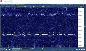
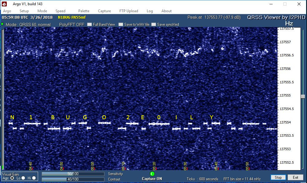
Message copied from 2E0ILY on the second night of the QSO (annotated). Note dots on the lower frequency, dashes shifted 0.187 Hz higher. When the signal is this strong, elements tend to bleed together a little but since they are of fixed length it is still very readable.

The next night it was my turn to listen. Due to the extremely slow speed DFCW is copied visually  using software designed for this purpose. Anxiously I stared at the screen. When I wasn’t nervously pacing, that is! I began to see traces of signal, then an odd letter here and there. There was a B, a 2, a Y and I even thought I saw an O but couldn’t be sure. Eventually conditions stabilized and I began to get steady print on the screen. Waiting 60 seconds for a dot or dash to fully paint on the screen can be agonizing. Slowly the elements accumulate and become characters. If you are lucky, propagation holds up long enough to copy the full message. Fortunately, after somewhat of a slow start copy remained solid and I eventually had N1BUG, 2E0ILY and a very nice O painted on my screen! I had copied full call signs and a signal report indicating Chris had got full call signs from me the previous night! We were half way there!

The third night I was transmitting again. Since I knew Chris had already copied full call signs from me, it was not necessary to transmit them at this stage of the QSO. Technically I could have just sent RO repeating throughout the night, but being of the cautious type I decided to include call sign suffixes to provide positive evidence the correct station was being copied. Thus the message I transmitted was ‘ILY BUG RO’. This was a risk as it takes far longer to send than simply ‘RO’ and signal fading can be a huge factor. At least the weather was better and I didn’t have to ride the variometer all night.

Soon it was night four, back to pacing and staring hopefully at the screen. I was especially nervous that night, as I had some strong, drifting interference right on top of Chris! Finally it moved just enough that I could make out ‘BUG ILY R’. There was rapid fading and the dash in the R was much fainter than the rest. Fainter but unmistakably there. I was positive about the R but being the cautious type and realizing this QSO would be an amateur radio first I really wanted to see it more clearly before declaring the QSO complete. The signal faded and nothing was seen for hours. Sunrise at 2E0ILY was fast approaching and I had to make a decision. Was I going to log the QSO or retransmit my RO message the following night in hope of getting better copy of the R on night six? Just before dawn the signal reappeared, very weak. I could barely make out ‘BUG IL’, then the ‘Y’ was quite strong. Given the proximity to sunrise every minute felt like an eternity. Ticking of the clock became offensively loud. It was going to take another four minutes to get an R! Would it hold up that long? Slowly, as the clock ticked and my heart raced, a crystal clear ‘R’ painted on the screen. There were traces of signal for some time after that but nothing  I would call readable, save a stray ‘Y’ that somehow came through well past dawn. So it came to be that shortly after 0600 UTC (1:00 AM local time) on this, the 28th day of March, 2018 I entered this QSO into my station log. We had done it!

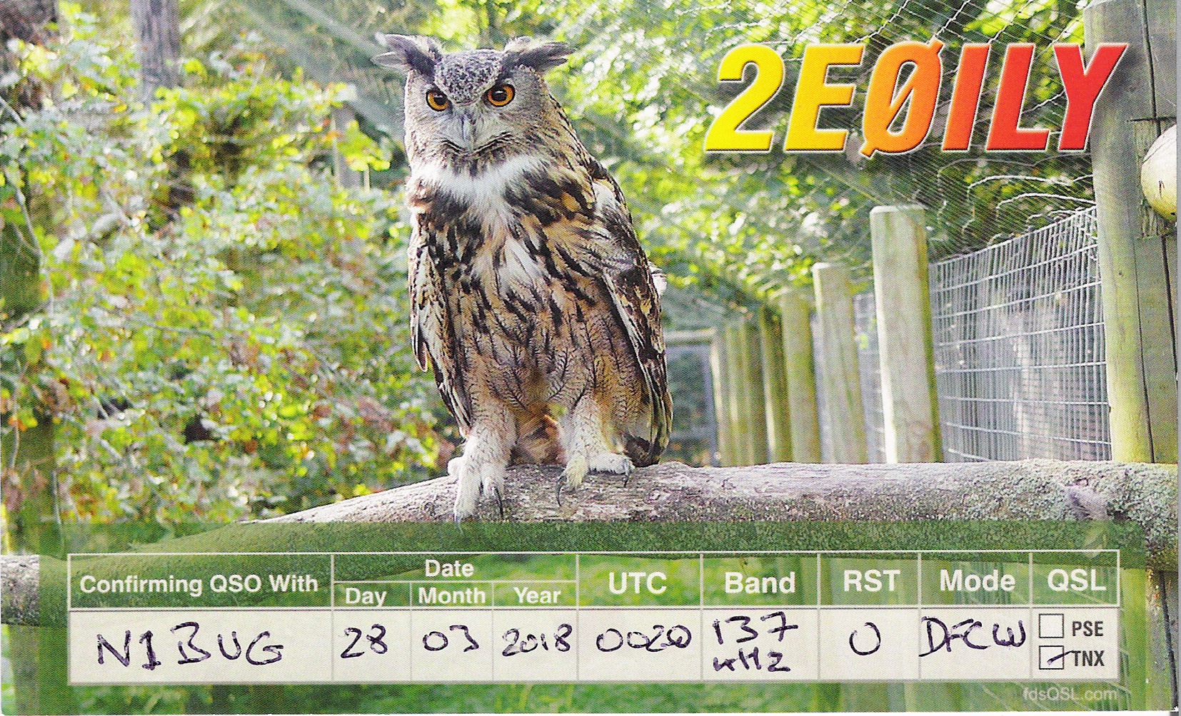
QSL card received for this very memorable QSO!

This was an amateur radio first from the U.S. but nothing new in terms of distance on the 2200 meter band. Canadian stations, operating under amateur call signs but otherwise a program similar to our Part 5 licenses, had worked Europe years earlier. Much longer distances had been covered. But for me this was one of the most exciting QSOs of my nearly 40 years as a DXer. It ranks right up there with my first EME QSO, the QSO that put me on the DXCC Honor Roll and several other notable events such as being credited with the first North American two meter auroral E QSO back in 1989. My thanks to Chris, 2E0ILY for his time and patience to make this happen – not to mention the kilowatt hours of electricity expended.

DFCW may be old school but it gets the job done under extremely difficult conditions. DFCW ‘decoding’ is done by the human operator. Deciding what has been copied is not left to computer software which may use assumption or non amateur radio means to fill in things it couldn’t positively make out over the air. DFCW is painfully slow but here we had a very positive over the air exchange of full call signs, reports and acknowledgement without any shortcuts or fudging. I was very pleased with that!

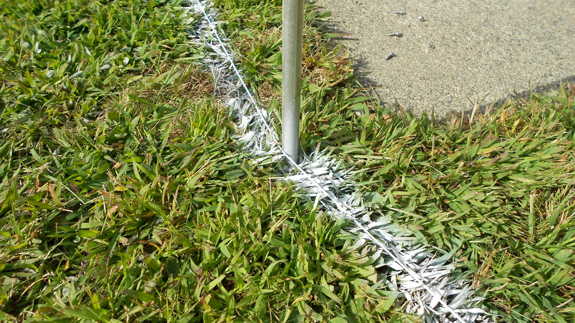
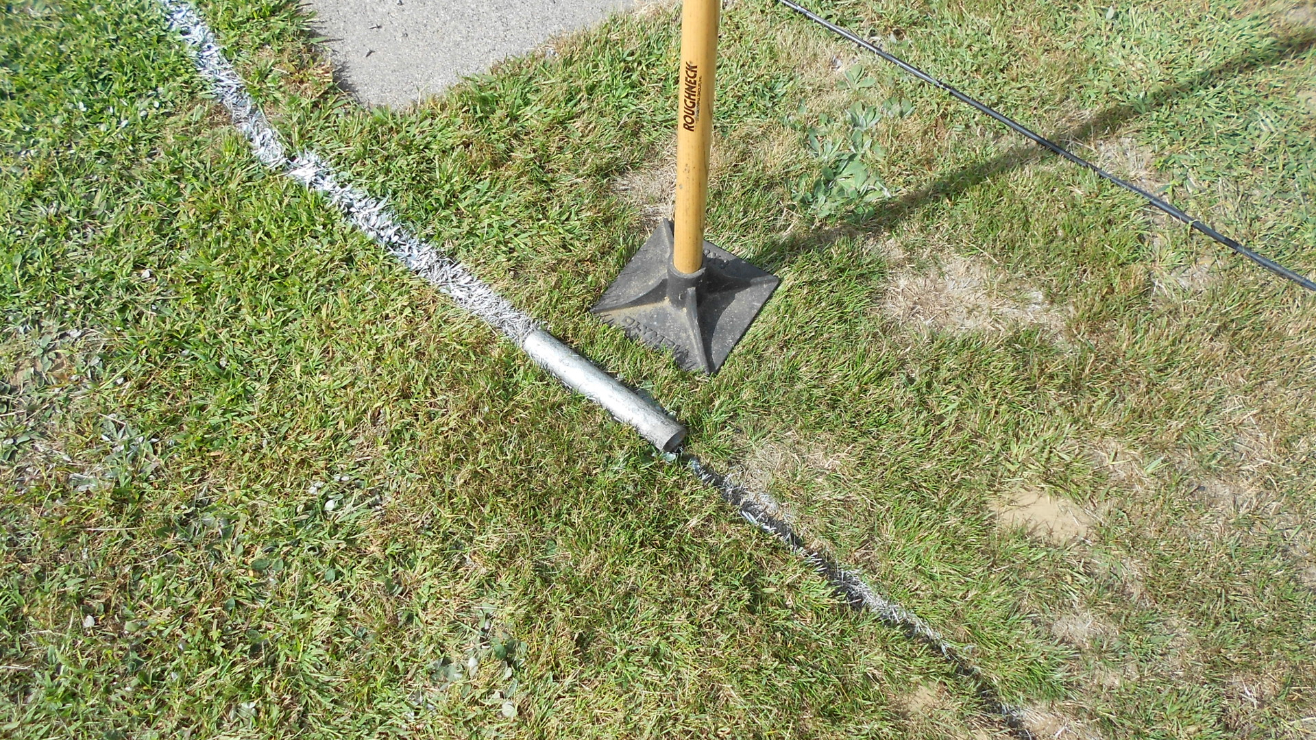
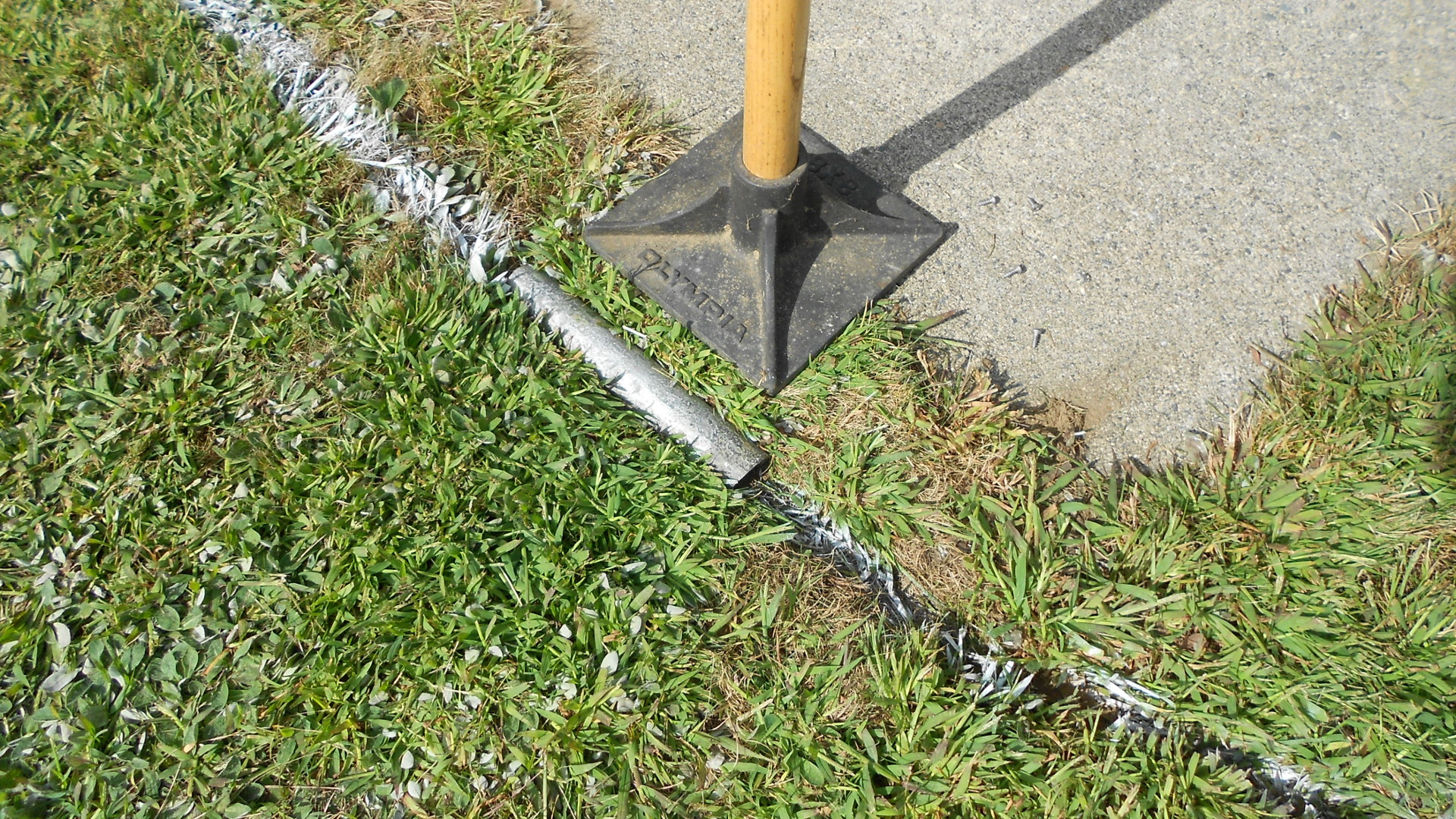
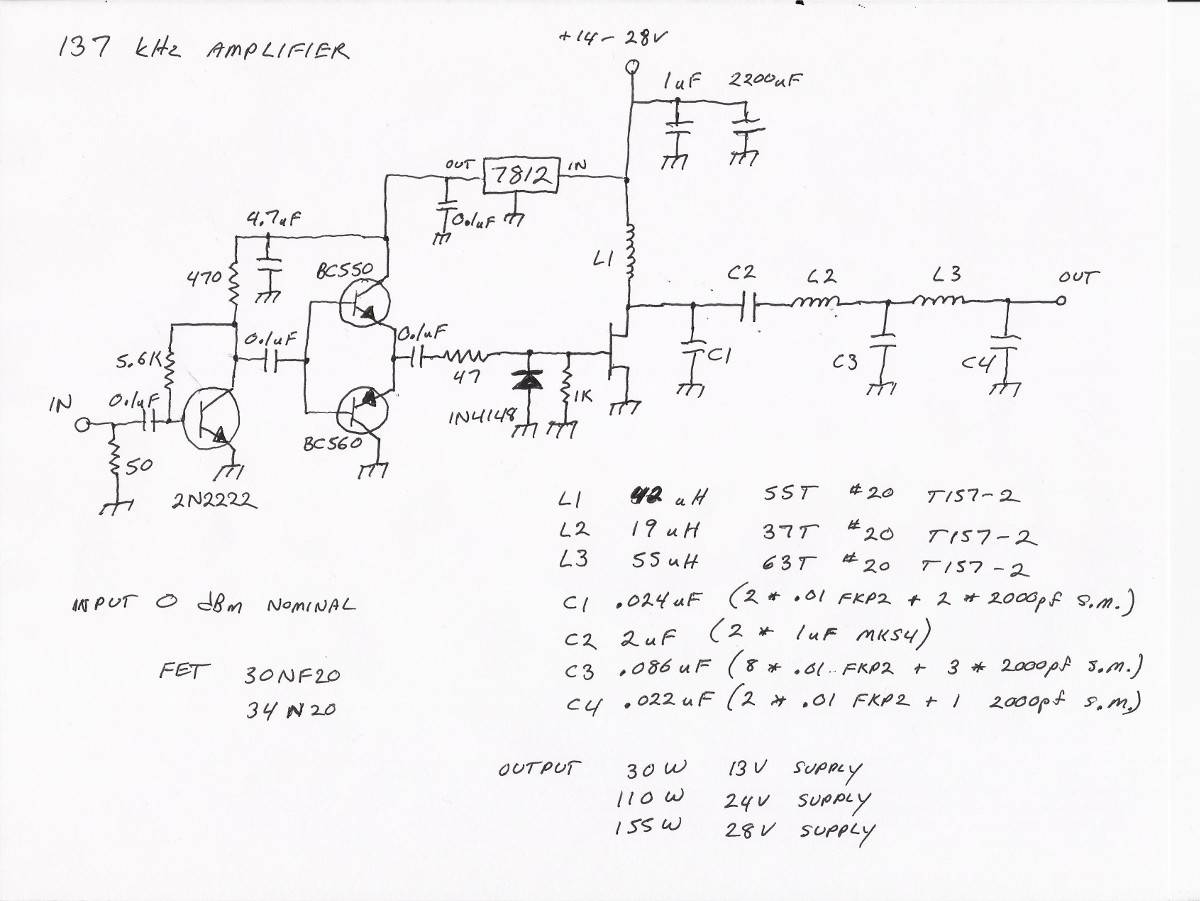
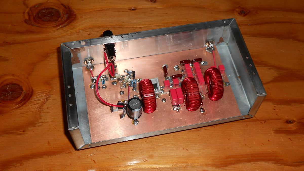
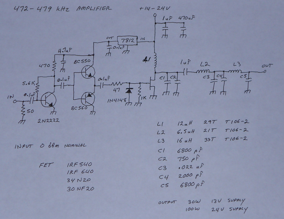
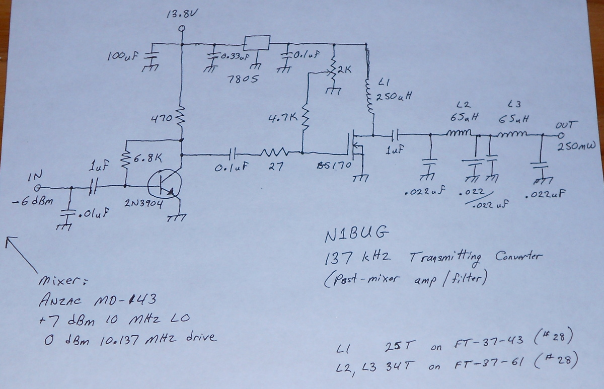
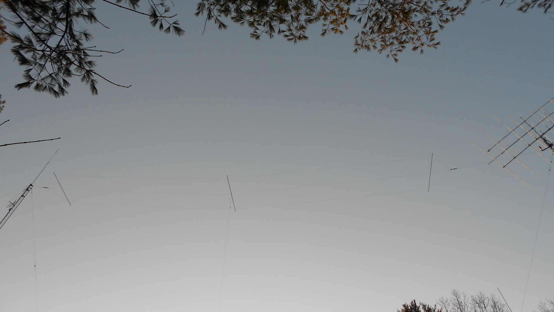
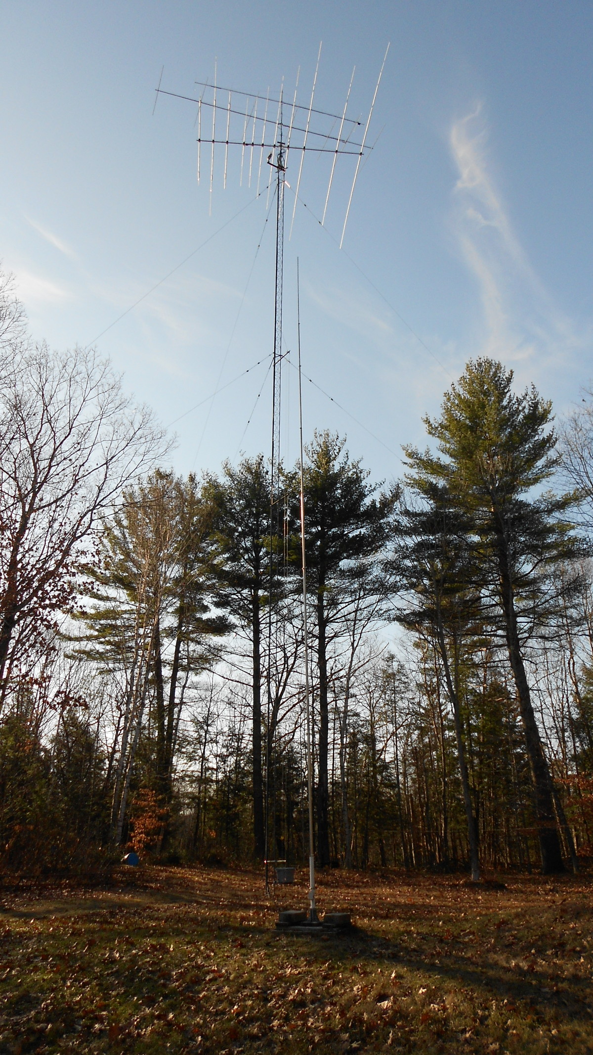
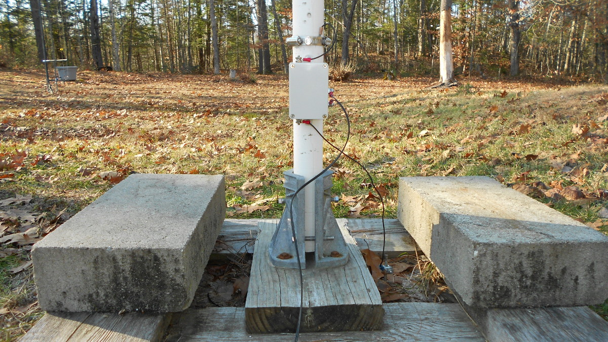
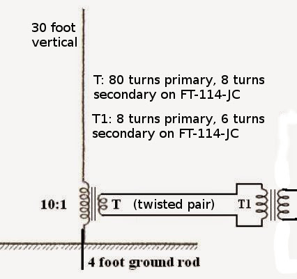
Although this single QSO cost more than any other, this was a low budget operation. Most of the LF station consists of low cost kits and home built gear. Equipment used at my station for this QSO was the QRP Labs Ultimate 3S driving a home built amplifier to 175 watts output. The transmitting antenna was a 90 foot Marconi (vertical) with a top hat consisting of three wires each 100 feet long, spaced five feet apart. Three one inch diameter aluminum spreaders plus triangular wire sections at each end are electrically part of the top loading. This is resonated at the base with an inductance of approximately 2.3 millihenries. Loss resistance at the time was near 100 ohms, resulting in EIRP of 0.5 watt. For receive I used a 30 foot low noise vertical, band pass filter, W1VD preamp, and a modified Softrock Lite II SDR receiver. The amplifier and most of the receive system has been described on my blog and/or web site. There are photos of the antenna and variometer on my web site.

A Low Drive 2200 Meter Amplifier

There is an updated post on this amplifier. I am leaving this post for historical purposes, but anyone interested in building it should refer to the new post.

Note 25 January 2019: The drain waveform has been corrected and this amp has run many hours at 250W output including some rather high duty cycle mixed WSR-15 / WSPR-2. It seems very reliable at that level. I will revise this post further when I have more time.

Note 12 May 2018: I have discovered this amplifier does not operate with a nominal Class E drain waveform. However that does not change the fact it has performed very well as described in this post. I intend to publish and updated version with corrected waveform at a later date.

While still planning and collecting parts for a high power 2200 meter amplifier I began to wonder if the design I use on 630 meters could be converted and made to work at 2200 meters – and if so, would I have the right parts to build it? Some quick math, assuming linear scaling of component values with frequency, showed that I just might be able to hit the correct values using parts salvaged from a problem ridden dual band amplifier I had given up on. So I set out to build and test a prototype. It took some fine tuning of inductor and capacitor values in the output circuit to get best efficiency and power peak at 137 kHz.

Schematic of the completed amplifier

Initially I used T106-2 cores for the inductors but in order to fit the required number of turns I had to use 24 AWG wire. Heating of the wire was excessive but otherwise the amplifier was showing a lot of promise. I decided to bite the bullet and order some T157-2 cores which would allow using 20 AWG wire. Note: heating of the wire in these inductors was not a surprise. My 630 meter unit does the same, as do several built by others. In the final design, it is possible to run high duty cycle at 100 watts output without a problem. For higher power I recommend a small fan blowing air across L1 and L2. It would probably be OK without the fan but I prefer to err on the side of caution. Capacitors C1 through C4 are made by connecting smaller values in parallel. I had a bunch of .01 uF 630 volt WIMA FKP2 capacitors and some 2000 pf 500 volt silver mica capacitors. These were the only two values needed when using the proper combination in parallel. The DC blocking capacitor is 2 uF, comprised of two 1 uF WIMA MKS4 capacitors in parallel. Initially I used a single 1 uF as in the 630 meter version but I found it was heating up slightly. Going to two of them in parallel resulted in no detectable heating.

The 22200 meter “junk box” amplifier

Construction is similar to the 630 meter amplifier discussed in an earlier post. “islands” were made by grinding away some foil from double sided FR4 material with a rotary tool and diamond bit. The finished amplifier can be driven with one milliwatt (0 dBm), like its 630 meter counterpart. Power output is similar. I measured in excess of 30 watts with a 13 volt supply, 110 watts with 24 volts, and 155 watts with 28 volts. In all cases, efficiency is 87 to 88 per cent. These figures hold over a range of 134 to 140 kHz. Outside that range it beings to roll off rapidly. I have been running mine for the past couple of nights at 28 volts and it seems fine. In the interest of disclosure I did have one FET die during testing but I had not been watching the antenna matching closely enough. Temperatures plummeted from the mid forties to the high single digits during that night of operation, causing the antenna resistance to drop sharply. This caused power output to soar above 200 watts before the FET finally gave up at 3:30 in the morning. I do not consider this a fault of the amplifier. Knowing how 2200 meter antennas are, the operator should have been watching more closely!

Update March 7, 2018: The amplifier has been running perfectly with no additional FET deaths. For more than a week I have been transmitting a combination of WSPR-15 (a good test for any amplifier) and WSPR-2 at 150+ watts output.

Update March 10, 2018: I cranked the voltage up to 30V and have been running the amp at 175 watts output for three nights with high duty cycle WSPR-15 and WSPR-2.

Some Thoughts on 2200 and 630 Meter DX

I came to these bands with a long history of being a 160 meter DX hound. Some of my perceptions and expectations were influenced by that history. Clearly propagation is more challenging at the lower frequencies and being limited to very low EIRP doesn’t help. Nevertheless I was expecting to find a hard core group of low frequency DXers clawing away every night in search of those elusive long distance QSOs. Reality has proven to be very different.

On 160 meters we have a good amount of nightly activity. No matter how late the hour one can find avid DXers CQing away, putting in chair time because with propagation being so variable that is what it takes for success. You have to be there consistently. On 630 Meters that isn’t the case. There is a good amount of nightly WSPR beacon activity which clearly demonstrates the potential for DX QSOs, but very rarely are there human operators behind radios running QSO modes at the times when propagation is there. It seems possible to motivate small numbers to get on and make an effort once in a while, particularly after a very good run of nights on WSPR. This is prone to failure since propagation is so unpredictable. On 2200 meters there is very little activity of any kind, including beacons!

It is, of course, very difficult for most people to be on the air late at night, which is when most of the DX potential exists at lower frequencies. If it isn’t late night at one end of a DX path, chances are it is at the other. The question I keep asking is why do we have a core group of ever present DXers on 160 but not on 630 or 2200 meters? Part of the answer undoubtedly lies in numbers alone. Let’s face it, there are many more stations with 160 meter capability than there are stations with 630 and/or 2200 meter capability. There are a number of immediately evident reasons for the lower number of capable stations. It becomes increasingly challenging to build a capable transmitting antenna system on the lower frequencies. Man made noise tends to be more of a problem and some people live in locations which are hopelessly  noisy. There is a lack of commercial equipment available, so these bands are, for the most part, occupied only by those who build their own. All of these factors contribute to keeping the number of active stations down. Fewer active stations means fewer who have the drive and ability to be on late at night. Numbers clearly play a role in DXing activity. It is actually a rather small percentage of 160 meter operators who are there night after night seeking DX QSOs. Similarly it will be a small percentage on the lower bands but with far lower numbers overall this tends to keep the number of avid DXers below critical mass.

But it probably goes deeper than that. To explain the lack of DXing activity we probably need to consider other factors. What are the motivations and rewards for working DX? For some it is simply the thrill of making that rare contact. For others it is the pursuit of long term achievements, collecting operating awards. There are many awards available to the 160 meter operator: DXCC, WAS, WAC, and many more. This isn’t true for the lower bands. For one thing, most awards are not even offered for these bands. If they were, most of the traditional major awards would not be attainable down here. DXCC is probably not possible for the vast majority of stations on 630 meters and probably not for anyone on 2200 meters. Propagation and the EIRP limits simply put it out of reach. WAS may be possible someday for those in North America (when we have active stations in all 50 states, which hasn’t happened yet) but is probably not possible for those in other parts of the world for the same reasons DXCC is impractical. WAC? Good luck, same problems. Are there in fact any available and reachable operating achievement awards for these bands? Not that I am aware of. So there is one motivation missing. If a well established and recognized organization offered attainable operating achievement awards for these bands, it might help to spur activity, perhaps even attracting more people to these bands in the first place.

Do these bands tend to attract a different group of people? Probably to some extent, yes. With lack of off affordable off the shelf equipment and no awards program, these bands may tend to attract mainly experimenters and those with special interests in low frequency radio. It may be that a large percentage are more interested in experimenting than in making QSOs. The results of the latest antenna change or transmitter upgrade can be easily and effectively assessed through beaconing, primarily using WSPR mode. One doesn’t need to be up late  sitting behind a radio for this. Clearly some of the operators who are on these bands are recognizable as DXers on higher bands — 160 meters, HF, even VHF and UHF. But they are a small minority.

I have given this a good deal of thought and continue to do so. What I have arrived at so far is a sense that we simply haven’t reached critical mass for DXing activity on either of these bands. It takes a certain amount of activity in in place to motivate most people to stay up late and get on the air. Even the most motivated operator may struggle to convince himself to be there night after night knowing there very likely is no one there to work. When activity is so low that there is very little chance of working anyone, the motivation is missing or insufficient. I am struggling with this myself. I am a very avid DXer  and I am very interested in trying to work as many stations and states as possible on 630 meters. But, looking at my unattended JT9 decodes each morning clearly shows the chances of working anyone out west on any given night are extremely low. So low, in fact, that I am usually unable to convince myself to stay up and try. Of course this works both ways as having few here in the east to look for probably keeps some in the west from being on every night. With the overall low number of capable stations, DX minded operators and fewer incentives driving the desire for QSOs, it is my opinion that we haven’t reached critical mass. There is not enough consistent activity to get the ball rolling and keep it rolling.

So how do we change this? Can it be changed? Would it help if there were a small group of extremely hard core DXers committed to CQing during key times every night? Perhaps this starts with those at the end of a DX path presenting more convenient hours. If those who would need to be up very late at night to make these QSOs had assurance that there were stations making noise, would this increase the likelihood that they would try? I am currently trying a limited run experiment along these lines, as I have committed to calling CQ every night this week for at least two hours during a time that is convenient for me and frequently offers propagation to Europe. The hours are not so convenient on the European end of the path! Unfortunately this experiment comes to an end when I finish repairs to the 2200 meter loading coil and return to that band. My one other thought on the subject is that those who do succeed in making DX QSOs on these bands should do everything possible to publicize this far and wide – both within and outside the LF/MF community. We need to show the world that long distance QSOs can be made on these bands! We need to promote them as QSO bands, as I believe the outside world still largely sees them as experimenter and beacon territory.

Update 10 January: Over the past several days an experiment was carried out. I announced that over a several night period I would be calling CQ on JT9 mode for at least two hours during the early part of the Europe to North America window (which tends to be the least inconvenient time for the Europeans). This attracted the attention of a few who indicated they would be looking for me. I promoted this as an activity period on both the European and North American email lists. I was joined on the North American side by NO3M and more casually by others. After a slow first night or two, I became the second in the U.S. to complete a trans-Atlantic QSO on 630 meters when I worked G3KEV (the first was AA1A working G0MRF several weeks earlier). Shortly thereafter, NO3M worked G3KEV. I had a partial QSO with PA0A. News of this success brought increasing interest. The following night both myself and NO3M worked G3KEV again. There were partial QSOs between N1BUG and OR7T, N1BUG and DK7FC, NO3M and DK7FC and possibly others but none of these were completed due to QSB or other factors. During this several night activity, hours of operation increased from two to four or more. That is a lot of chair time and CQing for very few QSOs. Clearly we have proven that many QSOs are possible but it will take dedication and effort. Frankly I do not have the stamina to sit there CQing four hours every night. If there were a large enough pool or interested operators to provide reasonable assurance that someone would be there every night, this might become self sustaining. As it is, we simply don’t have that level of activity.

Having more DX-minded operators on the bands would help. But getting on these bands can seem intimidating. There are some web sites that make it all sound so technical and complicated as to scare people away. It doesn’t have to be complicated. Probably the most challenging aspect is knowing what your EIRP is. If you can make basic measurements such as antenna system resistance and antenna current there are online calculators that take the work out of this. Chances are most hams have access to someone with the equipment to make such measurements if they don’t have it themselves.

Home built equipment can be very cost effective but one can buy a transmit converter for $80, a power meter for $40 and throw some wire in the air. If you don’t already have a receiver that works on these bands, there are inexpensive converters and simple SDRs that don’t cost an arm and a leg. There are some pricey equipment options out there. I don’t claim the cost is entirely unwarranted for those who can afford it. But it is not necessary to spend a fortune to get started or even to build a very capable close-to-high-end station. If you’re looking for intercontinental DX you will want to take the time to get up near the legal limit on EIRP but it can still be done on a budget.

For the time being, I suggest the most likely means of working DX is to organize and promote occasional “activity periods” where several stations at both ends of a DX path commit to calling CQ during a certain window for one or more nights. In the long term we need more DX-minded, motivated operators on the bands. Active promotion of the fun and challenge of DX QSOs on these bands is needed. A sensible awards program might be helpful.

A Low Drive 630 Meter Amplifier

My first attempt at amplifier building for the new low bands was a disaster. Being low on funds and patience at the time, I tried building a dual band “linear” amplifier that was said to be capable of 25 to 50 watts on both bands. It turned out to be a design plagued by problems which I won’t get into here. I was fretting about what to do next, as there was no budget at all, when Ken K5DNL came to the rescue. He kindly helped with parts and schematic for a modified, low drive version of the popular GW3UEP amplifier. Credit for the design goes to GW3UEP and K5DNL. Where I have made minor changes I will note that in this post.

Schematic of the low drive amplifier

Referring to the schematic, the 2N2222 provides additional gain to fulfill the low drive objective. This amplifier can be driven to full output with 0 dBm (one milliwatt) input. Mine actually produced full power down to -2 dBm but don’t count on every build being exactly the same. The BC550/BC560 pair forms a squarer to ensure we have a nice clean square wave to drive the FET. The FET in the original GW3UEP was a IRF540. Ken sent a couple of 30NF20 FETs which is what I used in mine. C2 and C4 were not on the schematic I received from Ken. After building it I found the gain and power output peak was around 505 kHz. Looking at the original design on GW3UEP’s web site I noted the the originally specified capacitor values were for that frequency, with a notation to add capacitors for 472-479 kHz operation. After I added C2 and C4, my amplifier peaked at 475 kHz. All capacitors in the FET output circuit should be good quality pulse rated film or silver mica. C1, C3, and C5 in my amplifier are WIMA FKP1. C2 and C4 are CM06 size silver mica with a 500 volt rating. The 1 uF DC blocking capacitor is a WIMA MKS4. Watch the capacitor voltage ratings. Theoretically, 100 volt capacitors should be good enough, though marginal if you intend to run on 24 volts. Some digging into spec sheets on the WIMA capacitors reveals voltage ratings are reduced as frequency increases and we are well down the slope on most of them at 475 kHz. If you are going to buy capacitors I suggest going with the highest voltage rating available. The other change I made was to relocate the blocking capacitor to the location shown. It was at the amplifier output on the schematic I received (and yes, if you are eagle-eyed you will see I have it at the output in the photo below. I relocated it later).

The completed amplifier. IMPORTANT NOTE: The 50 ohm shunt input resistor shown on the schematic is brown in color and mostly hidden under the input coax, just to the left of the 0.1 uF input coupling capacitor. The six blue resistors seen in the photo are not on the schematic. They form an input attenuator, needed because I am driving this amplifier with 250 milliwatts. The input attenuator takes that down to 1-2 milliwatts which is a perfect input level for the amplifier as shown in the schematic.

It should be noted that one need not use exactly the parallel combinations of capacitors specified. The important thing is that by whatever method, be it a single capacitor or several in parallel, we arrive at the required total capacitance at each point in the circuit. You will notice my capacitor combination at C3/C4 quite different from the original GW3UEP.

This amplifier should produce 30 watts output at 13 volts, 100 watts on 24 volts. I am running mine on 19 volts and getting about 65 watts out into a 50 ohm load. I have been running this amp on WSPR at 33% duty cycle for several days and it has performed perfectly. One should strive to keep the antenna resonant and matched, but mine has at times wandered off a bit with no ill affect on the amplifier aside from power output variation as the load impedance changes.

Note: This amplifier has a built in low pass filter but it does not meet FCC requirements for spectral purity. If you are subject to FCC regulations, you should use additional low pass filtering after this amplifier.

Building a 630-Meter Transmit Converter

Inside view of completed 630m transmit converter

This is a companion to my earlier 2200-meter transmit converter. Refer to that post for more details. This one produces about 25 dBm output. Not much is different here except for component values in the low pass filter and the trimmer potentiometer. I didn’t have another of the same type and value. It isn’t critical since it is only being used as a voltage divider to set bias on the BS170 FET.


Schematic diagram and parts values for the 630m transmit converter

Building a 2200-Meter Transmit Converter

I recently began running a WSPR beacon on 2200 meters. Beaconing is fine, but I also want to be able to make QSOs on this new band. To that end I needed a very low cost transmit converter so that I could use my FT-2000, which is fully interfaced to the computer for digital modes. Dave, AA1A came to the rescue with an old Anzac MD-143 mixer. The rest I built from stock parts and the junk box. Stock parts are new, current production parts I keep on hand for projects. The junkbox is a collection of old, surplus, used, salvaged and anything else I happen to be able to get my hands on. I don’t need a linear converter or amplifier for this band, and the resulting converter is not linear. It can be used on CW and any mode which does not require linear amplification.

The converter post-mixer amplification and low pass filter are separate from the mixer

The MD-143 takes a nominal 7 dBm local oscillator signal in the 5 to 500 MHz range. For RF it likes about 0 dBm in the same range. Conversion loss is around 6 dB so we can expect about -6 dBm output at the IF port, which is rated DC to 500 MHz. I wanted to get that up to 24 dBm (250 milliwatts) so it provide the same amplifier drive level as my Ultimate 3S beacon transmitter. The fewer things I have to remember when switching modes, bands, activities or exciters the better! I knew I could use a BS170 FET and low pass filter to duplicate the amplifier section of the Ultimate 3S but I would need something on the order of 10 dBm drive to assure equal output. Wayde, K3MF, suggested using a venerable 2N3904 and kindly sent a long a copy of a schematic. This was good because I have a drawer full of 2N3904 transistors! Some quick and dirty breadboarding and testing showed that I could get 12 dBm out of it with -6 dBm input from the mixer. Perfect!

Inside view of the completed post-mixer amplifier and low pass filter

I set about throwing a circuit together. I was only going to be building the post-mixer amplification and low pass filter stages since I wanted to use the Anzac mixer with this and a similar unit for 630 meters. It’s really very simple: a 2N3904 which produces a nice square wave output followed by a BS170 and finally a low pass filter. There is a 5 volt regulator to power the BS170 in order to hold it to the 24 dBm output level, same as in the Ultimate 3S which runs on 5 volts. After throwing the thing together, it showed exactly 24 dBm output on the first try! Whoa… let me note this on my calendar. It’s a historic occasion!

I am temporarily using my trusty HP 3325B function generator as a 10 MHz local oscillator. When I can afford it I plan to get a dedicated 10 MHz LO for this converter, ore more appropriately one that can be shared between this and its soon-to-be-built 630 meter counterpart. My FT-2000 has been modified for general coverage transmit so I can use it on both bands (10.135.7 to 10.137.8 for 2200 meters and 10.472 to 10.479 for 630 meters.

There is not much else to say about this. I am including a schematic for those who may wish to borrow ideas from this simple gadget. Unfortunately I am reduced to posting photographs of schematics since my printer/scanner finally died after many years of faithful service.

Schematic diagram of the post-mixer amp and LPF stages of the converter


Finally QRV on 2200 Meters!

Results of my second night of WSPR transmissions. W3PM is 1909km from me.

I have been so busy with station building projects that I have failed to write about several of them. Those have resulted in my station being able to transmit on the 2200 meter band after nearly ten months of work toward that goal. In my first two nights running a WSPR beacon at 12 watts transmitter power I have been heard by more than a dozen stations at distances to 1909km (1186 miles). My effective isotropic radiated power (EIRP) is less than 0.1 watt, which is 10 dB down from the legal limit. I am confident my station can span the Atlantic on this band when I reach full legal limit.

My sincere thanks to NI7J/WH2XND for help getting QRV, also to K7PO/WH2XXP for help with an upcoming project to increase transmitter power.

My transmitting antenna is a Marconi in a T configuration with 27m vertical and a top hat consisting of three 30m parallel wires spaced 1.5m apart.

This is the loading coil / variometer for the antenna. Maximum inductance of this coil is 2500 uH. My antenna requires about 2250 uH to resonate at 137.5 kHz. I’m still thinking about a proper replacement for the spring clip.

Low Noise Vertical for LF and MF Receiving

The LNV antenna with my southwest tower (which is the transmitting vertical for 160 meters) behind it

Note 12 May 2018: I moved this antenna to a new location and made a discovery. It had been working in part due to mutual coupling with my transmitting antenna. I should have known this because when I resonated the transmitting antenna on 2200m the LNV noise floor and signal levels came up about 20 dB on that band. Similarly when I resonated the transmitting antenna on 630 meters, output of the LNV came up nearly 10 dB on that band. When I moved it away from the transmitting antenna, output on both bands dropped to within 3 dB of my receiver noise floor even with the preamp (my simple SDRs are not ultra sensitive). Another factor may have been that the new location was surrounded by trees. The antenna has been moved back to its original location. Subsequently, a new receiver allows noise from the LNV to be about 12 dB above the receiver noise floor.

During the initial phase of experimentation I had found that some of my 160 meter Beverage antennas worked reasonably well for receiving on 2200 and 630 meters. I was hearing plenty of Europeans on both bands. Obviously at these frequencies they didn’t work as Beverages. What the actual operating mode was I don’t know. There were a few problems with this arrangement, primarily that I couldn’t run LF and MF receive operations concurrently with 160 (or 80) meter DXing. That was not good!

After reading a number of blog posts and web articles about the “low noise vertical” or LNV, I decided to give it a try. VE7SL has an article on his blog with links to additional information. As is often the case I pulled ideas from several sources, then mixed and matched (and even went off on my own a bit) for my version. My LNV is a 30 foot self supporting vertical made from scrap aluminum tubing I had on hand. It starts out with 1.5 inch OD at the base and tapers to 1/2 inch at the top. The bottom foot of the vertical is slid inside a two foot piece of 1.5 inch schedule 40 PVC pipe and secured in place with set screws (bottom) and a worm clamp (top). Looking at the photo that may be confusing. The set screws (three 1/4-20 stainless tap bolts)  go through the worm clamp and PVC just above the transformer box. You can see that in the photo. What is not visible is the other worm clamp securing the aluminum tubing to the top of the short PVC section. These details are unimportant. Just make sure your vertical is insulated at the base! A piece of wire hanging from a tree would no doubt work just as well, but I wanted to do mine this way.

The base of the LNV antenna with transformer inside the plastic mini box

A couple of words about the overview photo at the top of this post. First, in the thumbnail you may not be able to make out the LNV in the foreground just to the right of the tower behind it. Second, usually the yagi antennas on that tower are lined up with each other! We had a recent storm with wind gusts to 70 mph which skewed things and I haven’t been up to fix it yet. The LNV is only 40 feet from that tower which is my 160 meter transmitting vertical (shunt fed). Thanks to good band pass filters, my 2200 and 630 meter receivers don’t react at all when I transmit with 1500 watts on 160.

In some write ups about the LNV it is said one needs more than one ground rod for best performance. Surprisingly I am using just one four foot “ground rod” which is a section of a stainless steel mobile antenna whip which I pushed into the sandy soil by hand! I plan to try adding real ground rods later but the antenna is working with the minimal ground. As of this writing it has heard 2E0ILY nine consecutive nights on 2200 meters.

LNV base transformer primary winding

My LNV is fed with about 250 feet of WD1A twisted pair wire which is laying on the ground. This is ex military field phone wire and is practically indestructible as long as you keep water out of the ends. It has three steel and four tinned copper strands in each conductor along with incredibly tough insulation that takes a lot of abuse. Any twisted pair wire should work fine in this application.

LNV base transformer secondary

The transformer at the antenna base is wound on a FT-114-JC core, 80 turns primary, 8 turns secondary. First, the 80 turn primary is wound directly on the core using 20 AWG enameled wire. If a non-coated core is used, it would probably be wise to wrap the core with some kind of tape before winding the primary. One end of the primary winding connects to the base of the LNV, the other end to the ground rod.

The primary was wrapped with teflon thread seal tape, then the secondary was wound over the cold (ground) end of the primary using 20 AWG solid plastic coated wire. Another layer of teflon tape keeps everything nice and tight. The secondary winding connects to the twisted pair feed line.

LNV base transformer in its protective box

The finished transformer is mounted in a small plastic mini box of the type that has a rubber gasket to keep out water. The ground and antenna connections are #8-32 stainless machine screws at opposite ends of the box, while the connections for the twisted pair feed line are together on one side of the box.

Twisted pair to coax transformer for the shack end of the feed line. The RCA connector has subsequently been replaced by a BNC

At the shack end of the feed line I use another FT-114-JC core with 8 turn primary (twisted pair from the antenna), 6 turn secondary for 50 ohm coax to the receiver (or in my case two receivers via a splitter).

After using this antenna for 10 days, initial results are very promising, especially on the lower band. I am not able to listen with this and the old antenna at the same time, but I am hearing 2E0ILY on 2200 meters much more often and with stronger signals than I ever did with the short Beverage. To the west it seems about on par with the Beverage. On 630 meters I don’t think it is quite as good, but I am hearing a number of Europeans.

Diagram of the LNV antenna

Update on 2200 Meter Trans-Atlantic Reception

On the better nights I continue to receive WSPR2 signals from across the Atlantic on 137 kHz. Like my early EME days decades ago, the thrill remains high. I get excited beyond reason every time I see one of these pop up in my list of decodes. When I can predict which periods a station will be transmitting, I find myself intently watching the waterfall during those periods to see if I can visually detect anything. There are a large number of periods when the signal can be seen but does not decode. Factors that can prevent a decode on an otherwise OK signal include fading, atmospheric static (which is becoming ever more a factor as Spring approaches), and local interference.

I am convinced that much more frequent Atlantic crossings are possible. There are many nights when no capable stations are transmitting during the peak hours (or at any hour).

Below is an updated list of all 2200 Meter trans-Atlantic decodes to date.

2017-01-29 01:20 DC0DX    0.137469 -27 JO31lk 0.2  N1BUG FN55mf 5399
2017-01-29 02:18 DC0DX    0.137469 -24 JO31lk 0.2  N1BUG FN55mf 5399
2017-01-29 04:14 DC0DX    0.137469 -27 JO31lk 0.2  N1BUG FN55mf 5399
2017-01-29 07:08 DC0DX    0.137468 -27 JO31lk 0.2  N1BUG FN55mf 5399

2017-01-30 06:12 DC0DX    0.137468 -25 JO31lk 0.2  N1BUG FN55mf 5399

2017-01-31 07:20 G8HUH    0.137425 -28 IO81mg 0.1  N1BUG FN55mf 4766

2017-02-01 07:10 DC0DX    0.137469 -27 JO31lk 0.2  N1BUG FN55mf 5399

2017-02-02 05:36 DC0DX    0.137469 -23 JO31lk 0.2  N1BUG FN55mf 5399
2017-02-02 05:58 DC0DX    0.137469 -24 JO31lk 0.2  N1BUG FN55mf 5399
2017-02-02 06:20 DC0DX    0.137469 -25 JO31lk 0.2  N1BUG FN55mf 5399

2017-02-06 04:26 DC0DX    0.137470 -24 JO31lk 0.2  N1BUG FN55mf 5399
2017-02-06 04:48 DC0DX    0.137470 -25 JO31lk 0.2  N1BUG FN55mf 5399
2017-02-06 05:54 DC0DX    0.137469 -26 JO31lk 0.2  N1BUG FN55mf 5399

2017-02-07 02:36 DC0DX    0.137470 -27 JO31lk 0.2  N1BUG FN55mf 5399

2017-02-14 22:32 2E0ILY   0.137551 -29 IO82qv 0.1  N1BUG FN55mf 4731
2017-02-14 23:28 2E0ILY   0.137551 -29 IO82qv 0.1  N1BUG FN55mf 4731
2017-02-15 04:40 G8HUH    0.137422 -24 IO81mg 0.1  N1BUG FN55mf 4766

2017-02-22 04:20 G8HUH    0.137424 -28 IO81mg 0.1  N1BUG FN55mf 4766
2017-02-22 04:30 G8HUH    0.137424 -25 IO81mg 0.1  N1BUG FN55mf 4766
2017-02-22 05:50 G8HUH    0.137424 -28 IO81mg 0.1  N1BUG FN55mf 4766

2017-02-23 05:06 G8HUH    0.137424 -26 IO81mg 0.1  N1BUG FN55mf 4766
2017-02-23 05:10 G8HUH    0.137424 -25 IO81mg 0.1  N1BUG FN55mf 4766
2017-02-23 05:14 G8HUH    0.137424 -24 IO81mg 0.1  N1BUG FN55mf 4766
2017-02-23 05:18 G8HUH    0.137424 -26 IO81mg 0.1  N1BUG FN55mf 4766
2017-02-23 05:22 G8HUH    0.137424 -27 IO81mg 0.1  N1BUG FN55mf 4766

2017-02-23 23:08 2E0ILY   0.137552 -29 IO82qv 0.02 N1BUG FN55mf 4731
2017-02-23 23:56 2E0ILY   0.137552 -27 IO82qv 0.02 N1BUG FN55mf 4731

2017-02-26 00:06 2E0ILY   0.137551 -28 IO82qv 0.02 N1BUG FN55mf 4731
2017-02-26 00:44 2E0ILY   0.137551 -28 IO82qv 0.02 N1BUG FN55mf 4731
2017-02-26 00:54 2E0ILY   0.137552 -28 IO82qv 0.02 N1BUG FN55mf 4731
2017-02-26 00:56 2E0ILY   0.137552 -28 IO82qv 0.02 N1BUG FN55mf 4731

2017-02-26 23:30 2E0ILY   0.137549 -28 IO82qv 0.02 N1BUG FN55mf 4731

2017-03-05 05:08 2E0ILY   0.137550 -28 IO82qv 0.2  N1BUG FN55mf 4731

2017-03-13 23:54 2E0ILY   0.137550 -27 IO82qv 0.2  N1BUG FN55mf 4731
2017-03-14 00:12 2E0ILY   0.137550 -27 IO82qv 0.2  N1BUG FN55mf 4731
2017-03-14 02:16 2E0ILY   0.137550 -28 IO82qv 0.2  N1BUG FN55mf 4731

2017-03-15 00:32 2E0ILY   0.137550 -28 IO82qv 0.2  N1BUG FN55mf 4731
2017-03-15 02:48 2E0ILY   0.137550 -29 IO82qv 0.2  N1BUG FN55mf 4731
2017-03-15 03:00 2E0ILY   0.137550 -27 IO82qv 0.2  N1BUG FN55mf 4731
2017-03-15 03:32 2E0ILY   0.137550 -27 IO82qv 0.2  N1BUG FN55mf 4731
2017-03-15 03:48 2E0ILY   0.137550 -25 IO82qv 0.2  N1BUG FN55mf 4731
2017-03-15 04:16 2E0ILY   0.137550 -27 IO82qv 0.2  N1BUG FN55mf 4731
2017-03-15 04:32 2E0ILY   0.137550 -27 IO82qv 0.2  N1BUG FN55mf 4731