Category Archives: MF & LF

2200m/630m Transatlantic Reception, January 26 to February 2

The past few nights have been very interesting on LF and MF. For starters, January 29 was the first time I heard Europe on 2200 meters. I have decoded at least one transmission from Europe on the band each of five nights since then. This may be in whole or in part due to a change I made to my receiving setup on January 29. However, a number of other curious things emerge when looking at the data.

For one thing, I did not decode any 630m transatlantic signals on the night of January 28/29, but I did decode DC0DX four times on 2200m.

The second thing of note is the decodes on the night of February 1/2. On 630 meters I only decoded EA5DOM, which is quite low latitude for a transatlantic path. The northern stations were completely missing, not only from Europe but also no transcontinental decodes from the VE7 or northern W7 areas. This would be a typical pattern given an upturn in geomagnetic activity from mostly quiet to active/minor storm. Yet this was the second best night for transatlantic on 2200m with three DC0DX decodes, including the best S/N yet observed.

The other thing of interest is that on 630m, excepting an early start by PA0A on the night of January 31/February 1, most of the decodes are about in the middle of common darkness; not near my sunset or near sunrise at the eastern end of the path. There is one late decode of EA5DOM on the night of January 30/31. On 2200 meters we find most of the decodes were late, not too long before sunrise at the eastern end. The only exception is three earlier decodes of DC0DX on the night of January 28/29.

Although not shown here, WH2XND on 2200m was notably weaker on the final night, February 1/2 than on the previous nights in this period.

There is insufficient data to draw any conclusions, but in the early days of hearing transatlantic signals on 2200m it does not seem to correlate well with what is happening on 630m. I wonder if any clear trends will emerge as more data is accumulated.


Transatlantic decodes, 630m, January 26 – February 2:

2017-01-30 02:36 EA5DOM  0.475610 -26 IM98xn N1BUG FN55mf 5578 301 
2017-01-30 02:48 EA5DOM  0.475610 -27 IM98xn N1BUG FN55mf 5578 301 

2017-01-31 00:12 EA5DOM  0.475610 -26 IM98xn N1BUG FN55mf 5578 301 
2017-01-31 01:12 G3KEV   0.475705 -23 IO94sh N1BUG FN55mf 4820 287 
2017-01-31 01:20 G3KEV   0.475705 -25 IO94sh N1BUG FN55mf 4820 287 
2017-01-31 03:16 ON5TA   0.475671 -27 JO20es N1BUG FN55mf 5264 293 
2017-01-31 06:24 EA5DOM  0.475609 -28 IM98xn N1BUG FN55mf 5578 301 

2017-01-31 21:48 PA0A    0.475730 -25 JO33de N1BUG FN55mf 5280 292 
2017-01-31 21:50 PA0A    0.475730 -27 JO33de N1BUG FN55mf 5280 292 
2017-01-31 23:50 PA0A    0.475730 -29 JO33de N1BUG FN55mf 5280 292 
2017-01-31 23:54 PA0A    0.475730 -27 JO33de N1BUG FN55mf 5280 292 
2017-02-01 00:24 G8HUH   0.475782 -26 IO81mg N1BUG FN55mf 4766 289 
2017-02-01 00:24 EA5DOM  0.475610 -27 IM98xn N1BUG FN55mf 5578 301 
2017-02-01 00:44 G8HUH   0.475782 -26 IO81mg N1BUG FN55mf 4766 289 
2017-02-01 00:48 EA5DOM  0.475610 -29 IM98xn N1BUG FN55mf 5578 301 
2017-02-01 00:54 G8HUH   0.475782 -22 IO81mg N1BUG FN55mf 4766 289 
2017-02-01 02:48 EA5DOM  0.475609 -27 IM98xn N1BUG FN55mf 5578 301 
2017-02-01 03:36 EA5DOM  0.475609 -28 IM98xn N1BUG FN55mf 5578 301 
2017-02-01 03:44 F1AFJ   0.475727 -28 JN06ht N1BUG FN55mf 5193 295 
2017-02-01 04:00 EA5DOM  0.475609 -30 IM98xn N1BUG FN55mf 5578 301 

2017-02-02 02:36 EA5DOM  0.475610 -28 IM98xn N1BUG FN55mf 5578 301 
2017-02-02 03:24 EA5DOM  0.475609 -25 IM98xn N1BUG FN55mf 5578 301

Transatlantic decodes, 2200m, January 26 – February 2:

2017-01-29 01:20 DC0DX 0.137469 -27 JO31lk N1BUG FN55mf 5399 294 
2017-01-29 02:18 DC0DX 0.137469 -24 JO31lk N1BUG FN55mf 5399 294 
2017-01-29 04:14 DC0DX 0.137469 -27 JO31lk N1BUG FN55mf 5399 294 
2017-01-29 07:08 DC0DX 0.137468 -27 JO31lk N1BUG FN55mf 5399 294 

2017-01-30 06:12 DC0DX 0.137468 -25 JO31lk N1BUG FN55mf 5399 294 

2017-01-31 07:20 G8HUH 0.137425 -28 IO81mg N1BUG FN55mf 4766 289 

2017-02-01 07:10 DC0DX 0.137469 -27 JO31lk N1BUG FN55mf 5399 294 

2017-02-02 05:36 DC0DX 0.137469 -23 JO31lk N1BUG FN55mf 5399 294 
2017-02-02 05:58 DC0DX 0.137469 -24 JO31lk N1BUG FN55mf 5399 294 
2017-02-02 06:20 DC0DX 0.137469 -25 JO31lk N1BUG FN55mf 5399 294

2200 Meter SoftRock Lite II

Any good project starts with some scribbling on paper…

With the 630 meter SoftRock Lite II working well it was time to turn my attention to putting one on 2200 meters. There is no standard SoftRock which covers this range so I would have to make a few component substitutions. The changes are all very minor except for the crystal which cost more than the SoftRock kit! Something around 455 kHz is ideal. I ended up buying a 455 kHz carrier crystal from INRAD. Several capacitors in the oscillator would need to be changed to higher values, namely C10 3900 pF, C11 2700 pF, and C12 680 pF. I also changed R16 to 10k ohms because I find the oscillator never runs properly with the stock value.

The front end was also going to need some changes. C3 becomes .005 uF. C4 should be .16 uF but I used a .15 and it worked well enough. L1 is 267 uH. I used 25 turns on a FT-37-43 core. T1 primary should be 8.23 uH. I used 12 turns on a FT-37-61 core. The secondary is 6 bifilar turns. This input circuit has a bit of loss (about 2 dB) but I considered that acceptable since I was unable to come up with a better design that was also practical. As with the 630 meter unit, additional front end selectivity would be needed. I duplicated the C3, L1, C4, T1 primary once more and placed the circuit on a small prototype board.

Internal view of completed receiver

The finished receiver works well. I have been hearing WH2XND very well every night. I have heard Europe on WSPR-2 mode four consecutive nights, three of those nights DC0DX and the one night G8HUH. There were no problems with out of band signals until I added a preamp, at which time I had to put an outboard bandpass filter in line to keep things clean. LO frequency stability is on par with the 630 meter unit. See my earlier performance evaluation on that for details. I am happy with the performance and this is now my primary 2200 meter receiver.

Final Test of SoftRock Lite II on 630-Meters

Response curve of three section filter

I built a small two stage band pass filter that fits in the box with the SoftRock. Essentially I took the half wave input filter used in the receiver front end and duplicated it twice, including the shunt inductance of the input transformer. Combined with that already on the SoftRock itself, this provides a three section filter which is more than 100 dB down at the second harmonic of the local oscillator (and much more at the third harmonic). Performance of the filter was verified on a spectrum analyzer after construction. It is virtually identical to the modeled plot shown here. It is always good when real world results match the design model!

Return loss of the three stage input filter

Some will argue that this filter is too simplistic. That may be true from a purist standpoint, but results have proved more than adequate. I wouldn’t call it a state of the art design. However it is very inexpensive and fits in a small space. Pass band loss is about 5 dB, mostly due to Q of the inductors. I wasn’t able to come up with a filter that looked better on reasonable size toroids without running into issues with overlapping turns and distributed capacitance causing problems. With any practical antenna (and preamp if needed) I don’t see this loss as a problem. Return loss isn’t great, but exceeds 10 dB across the pass band, which is approximately 420 to 520 kHz. In a receive application I see no problem with this. The input impedance of receivers is all over the place, some much worse than this one.

Live results are gratifying. Even with one of my 22 dB gain W1VD preamps in line, there was no sign of broadcast stations appearing in the useful range of the receiver. (Note: I don’t need the preamp with my receive antennas. I only used it as an acid test to evaluate filter performance, since it makes the signals we want to reject that much stronger.)

Inside the completed receiver

The receiver and filter fit nicely into a Hammond 1590BBK diecast box which gives it a nice look in a compact package. I probably didn’t need to use miniature coax (in this case RG-188) for the very short runs interconnecting the BNC input connector, filter board, and SoftRock. At this frequency and with this layout, the very small capacitance between unshielded wire leads would probably not cause harmful leakage around the filter. But I have a bunch of this stuff, so why not use it? Besides, the teflon cable is a joy to work with. The insulation on most of the small hookup wire I have melts easily while soldering. Not this stuff!

Building this receiver was a pleasant and worthwhile experience. I finally understand how simple SDRs work. Studying the schematic, reading the descriptions of individual stage function, building it and probing various locations in the receiver with an oscilloscope and spectrum analyzer was very enlightening. I learned more about filters. Perhaps most importantly, I am no longer afraid of projects involving surface mount components. Performance of the completed receiver is good enough that I can recommend it to anyone wanting a simple, inexpensive receiver for the 630 meter band or anything else in the 420 to 520 kHz range (with a sound card sampling at 192 kHz the receiver will tune 368 to 560 kHz, but the filter cuts off at 420 and 520 kHz). It outperforms my FT-2000 in every measurable way. If there is one caveat it would be that if one wished to use it for serious reception of QRSS or DFCW signals it either needs to be well insulated or have a crystal heater added. For everything else its frequency stability is excellent. To my knowledge there is no QRSS or DFCW activity on 630 meters at the present time.

Update 19 January 2018: Adding schematic for the two additional stages of front end filtering. Coils are the same as those in the Softrock Lite II 455 kit.

External band pass filter schematic

More Evaluating the SoftRock Lite on 630-Meters

Last night I decided to run a few tests. I don’t have an elaborate lab, but I do have two calibrated signal generators and some other test equipment.

What I had read about the SoftRock not responding to signals on even harmonics of the LO frequency is not true according to my tests. First I looked at MDS (minimum discernible signal) at 474 kHz (LO frequency + 10 kHz) with a signal generator connected to the receiver. I could still clearly see the signal in HDSDR at -135 dBm. Next I measured at 938 kHz (2 x LO frequency + 10 kHz) and got -57 dBm. At 1402 kHz (3 x LO + 10 kHz) I found it to be -53 dBm. There are some things I don’t understand about this result. Theoretically at 1402 kHz it should be down no more than the SoftRock front end filter attenuation at that frequency plus a few dB because the LO third harmonic is 10 dB down from the fundamental. According to my modeling of the filter and spectrum analyzer sweep of the same filter outside the receiver, it attenuates 41 dB at this frequency. 41 plus 10 is only 51 dB down according to theory. Yet I was seeing 82 dB difference in MDS. That doesn’t make sense to me. What is clear both from this test and from those broadcast stations I was able to identify while listening on the SoftRock is that both the second and third harmonic response is considerable.

I spent several hours carefully examining the strength and number of broadcast signals making it through the front end selectivity. My external bandpass filter removed all traces of broadcast stations being heard with the receiver. Its calculated and measured response is -60 dB at 900 kHz, -84 dB at 1400 kHz. The filter I plan to build for the SoftRock should be -66 and -88 dB respectively.

I attempted to run a close spaced IMD test on the receiver. With signals on 473 and 474 kHz, I detected no IMD products when both of these signals were 90 dB above the noise floor. This is probably sound card dependent but it indicates to me that the SoftRock hardware has good strong signal performance. I reduced one signal to barely audible and left the other at 90 dB above noise floor. Switching the strong signal on and off did not noticeably affect my ability to hear the weak signal. I need a different test setup to go beyond 90 dB in these tests, though I am satisfied it is as good as it needs to be.

This continues to look like it should be a relatively low cost, high performance 630 meter receiver once the added front end filtering is in place.


More on SoftRock Lite II 630-Meter Performance

Last night I performed additonal tests on the Softrock to determine the impact of third LO harmonic response in the medium wave broadcast band. Broadcast signals were stronger than the previous night and the situation got ugly in a hurry after sunset. This receiver will need external filtering to be useful on 630 meters.

Here is a recording of the 630 meter WSPR segment, first without and then with an external bandpass filter.


That just about says it all, but here are some images that tell the story. I will be trying a prototype for a filter designed specifically for this application and will post about that when finished.

Here we see the entire available band when using a sound card sampling at 192 kHz. This is with no external filtering. Note the many spikes in the center pane. Many of these are broacast stations that are not really in this band.

Full band view with external band pass filter. Note how many of the signals disappear.

Zoomed in view of 630 meter band without external filtering. Note the broadcast signal right in the middle of it.

This shows the 630 meter band with an external bandpass filter. The unwanted signal is gone.

This is the WSJT-X waterfall. I had the external filter in for most of this. I switched it out breifly at around 2335z. Notice all the junk that shows up, wiping out the WSPR signal.

Evaluating the SoftRock Lite II on 630-Meters

This is not intended as a review per se of the SoftRock Lite II with 455 kHz IF option. This is a summary of my experience with the receiver during initial evaluation. My test methods are certainly not standardized and results may be unique to my environment.

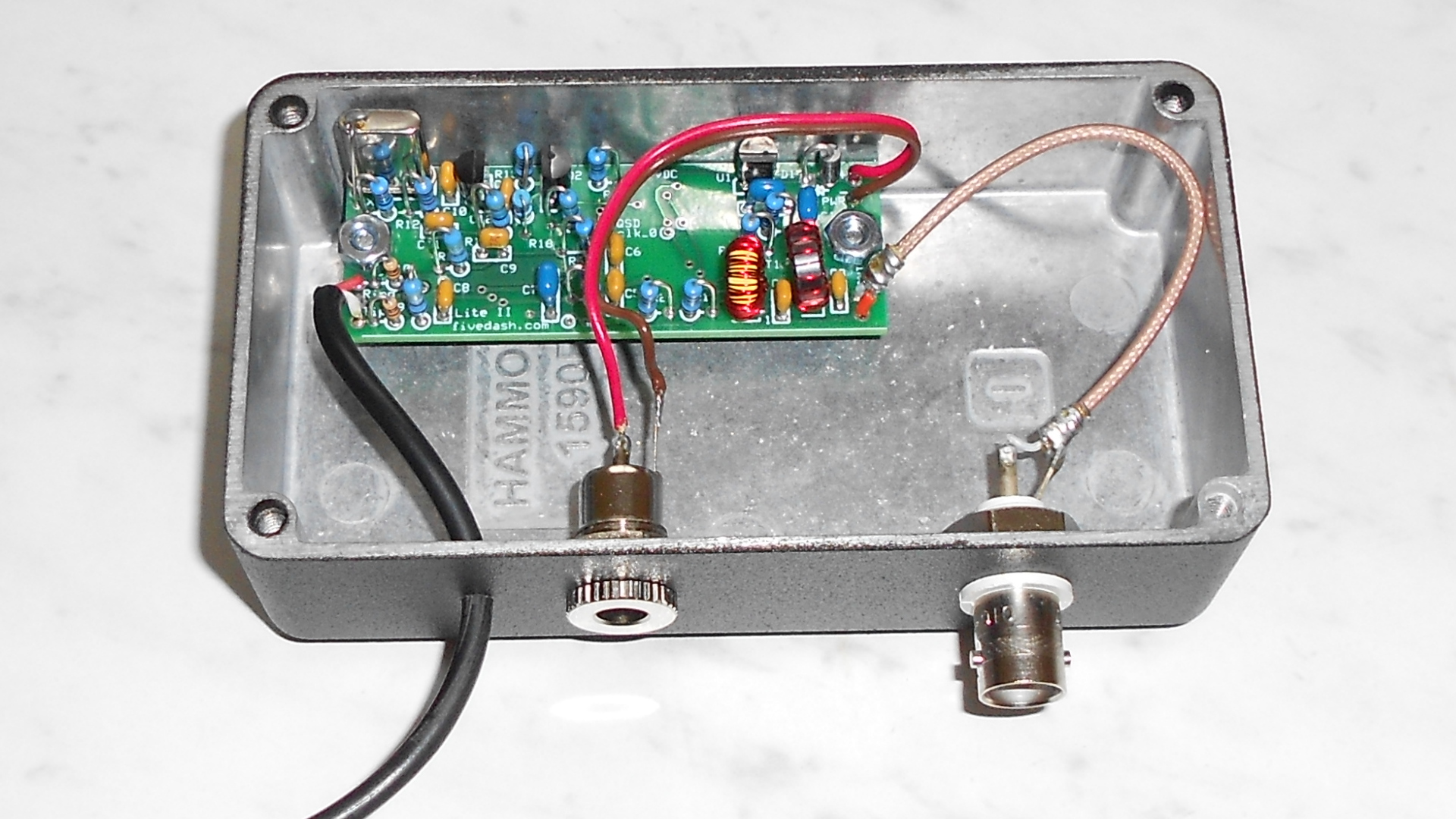
The build notes for the kit were often confusing but there were plenty of warnings that one should not expect this to be like assembling a Heathkit with detailed step by step instructions. They sometimes tell you to do something, then in the next paragraph tell you to be sure to do something else before the step they just talked about. I suggest reading ahead before doing anything. There are some typos and inconsistencies. The part about the toroidal transformer I found particularly confusing. They use the terms primary and secondary interchangeably. I found it necessary to read the various links for more information and weigh various statements against others to understand what I was actually supposed to do. I do not feel this is a project for a first time builder.

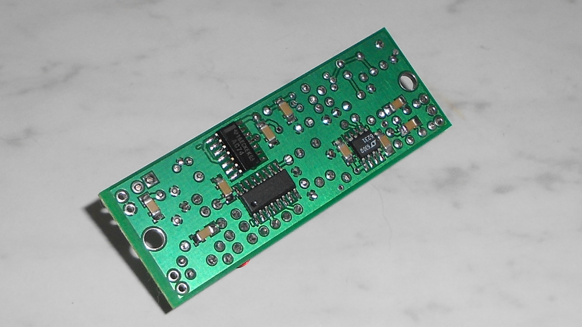
The oscillator did not work properly without changing one of the bias resistors on Q2. R16 had to be changed from 22.1k to 10k in my case. Reading through the archives of the softrock40 Yahoo group this seems to be a very common issue, yet it is not mentioned in the build notes. I would have preferred to know going in so that I could perhaps decide to mount R16 differently in case it had to be removed later.

Customer service was absolutely outstanding. There was a kit packaging error with the unit we received. When I contacted Tony about it, he was very friendly and immediately mailed the correct packet of parts (the extras needed for the 455 IF option) to me even though I was not the purchaser of the kit, merely the builder.

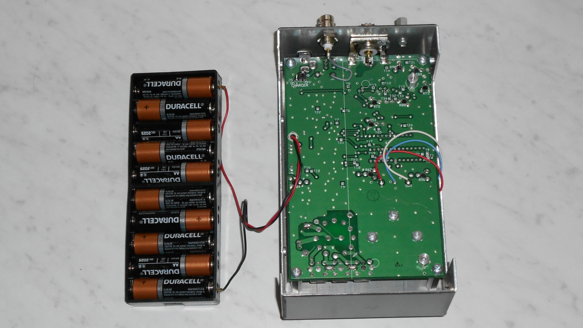
I suggest heeding the advice about trying the receiver on battery power first. I stupidly connected the test sample to my station’s main 12 volt bus and then spent the better part of two days trying to troubleshoot a receiver that, as it turned out, didn’t have a problem! My 12 volt bus runs many things including some network devices. I discovered during this process that it has about 400 millivolts peak to peak of noise. This manifested as a rather complex AC waveform riding on top of the DC. I don’t know if that was the problem or the fact that connecting to this bus grounds the SoftRock PCB to the station ground, which they warn you not to do. I am not certain exactly how this messed up the SoftRock but the receiver was completely deaf. I could see a lot of noise on the RF signal going into the mixers when I probed it with a scope or spectrum analyzer. The level was also jumping around all over the place. I saw similar noise on the mixer output, and all I could hear from the receiver was a low level buzz. The in-circuit waveforms I saw around the mixer bore a striking resemblance to what I  later discovered on the 12 volt bus. The receiver works fine on a 9 volt battery and on an isolated linear wall wart.

What about performance? First of all, this receiver’s sensitivity is excellent, far more than needed for MF operation.

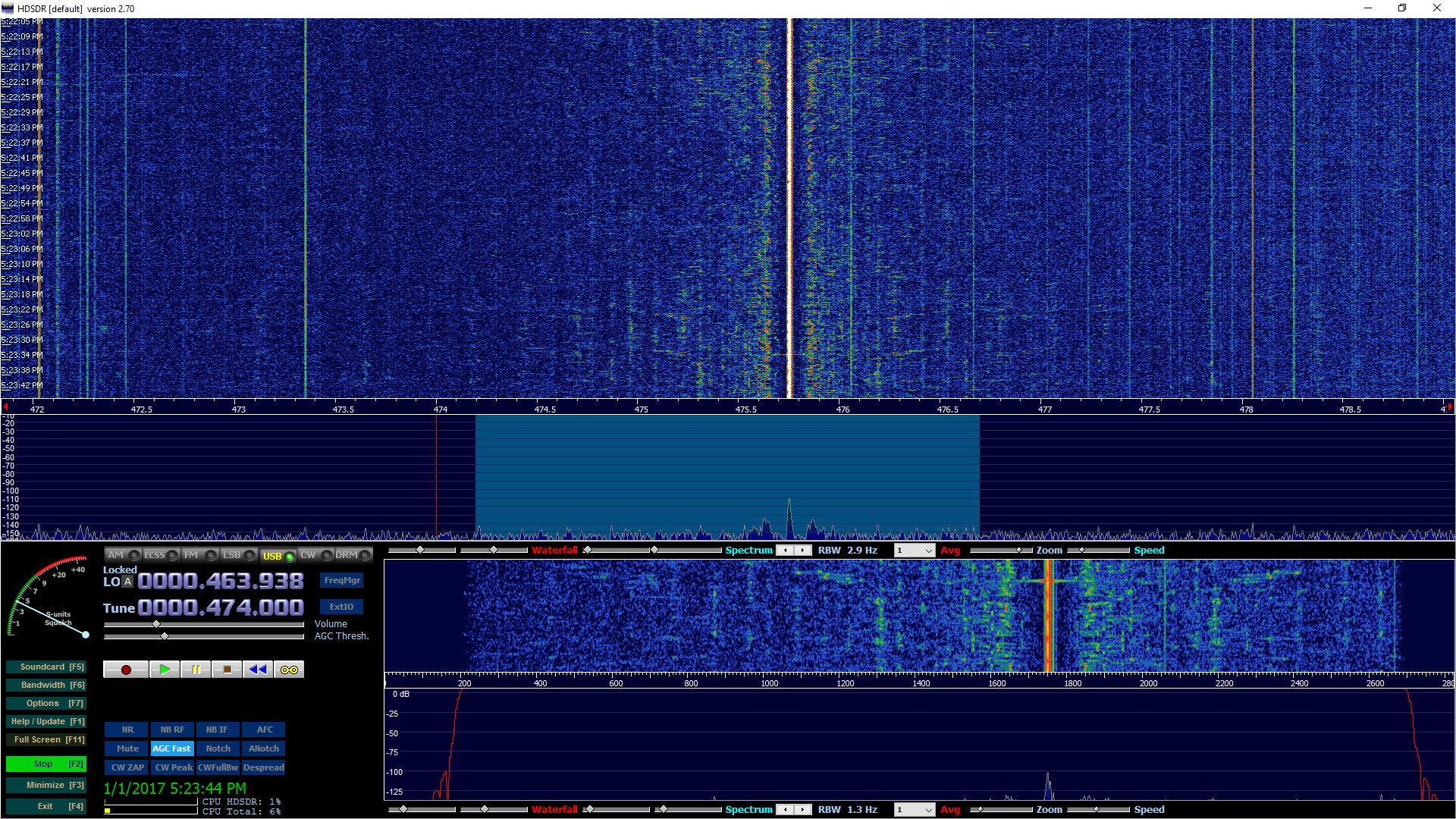
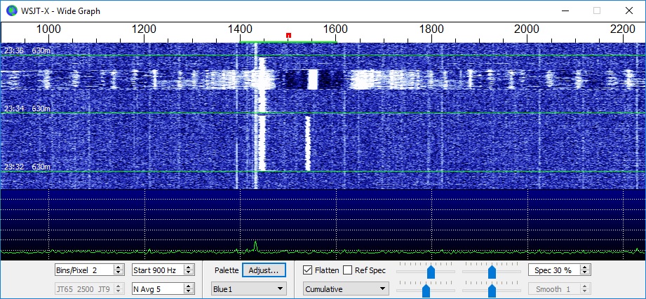
Its local oscillator is more stable than I would have expected. My test setup involves putting a very low level (inaudible) signal into the receiver from my HP 3325B function generator. Drift of the HP is on the order of a couple of milliHertz regardless of environmental changes so it is a reliable standard for this test. I monitored the output of the SoftRock using Argo set to QRSS30, QRSS60, and QRSS 120 in order to get different resolutions. With this setup  I can measure drift to better than +/- .01 Hz. Here are a few more details on this setup. I fed signal from the HP 3325B to an unused input on my receive antenna switch. This allowed me to monitor 630 meter WSPR activity using WSJT-X while simultaneously evaluating drift with Argo. I set the injected frequency to 475,900.000 Hz, which is 100 Hz above the top of the WSPR band. Since I was feeding an unused port on the antenna switch, I had some 80 or 90 dB attenuation; thus the minimum output level of the 3325B (-56 dBm) was not a problem. The I and Q outputs from the SoftRock are fed to an HTOmega Claro sound card which can sample at 192 kHz. I used HDSDR for the receiver, piping its output audio through VB Cable to WSJT-X, Argo, and Spectran. The latter was used only as a convenient means of outputting the audio stream to my speakers.

Before making any measurements, I calibrated the LO frequency and front end in HDSDR. The Claro sound card gives more than 100 dB rejection of the image frequency (test conditions: 474.000 kHz input, image around 454 kHz). My other sound card, which is VIA HD audio on the PC motherboard was not as good, providing only about 75 dB image rejection after careful tweaking. It also overloads at a level much lower than the Claro.

With the SoftRock sitting in a typical spot in my shack, cover removed from the Hammond box to allow free air flow, there is a cyclic drift of less than +/- .06 Hz as my furnace cycles and ambient temperature in the shack varies a few degrees. In another location (affected by heat of my rack mounted PC), cover on, cyclic drift associated with furnace activity was +/- 0.15 Hz. When I wrapped the receiver in a towel and stuffed it into a plastic bag the cyclic drift was less than +/- .01 Hz. Lastly I conducted an open air test (cover off) observing frequency change with a 10ᵒF temperature change in the room. it moved 0.7 Hz. Stability of this unit is more than adequate for CW, WSPR, JT9 and other fast or slow modes. Except when wrapped in a towel and plastic bag, drift becomes an issue for super slow modes such ad QRSS30 and slower or DFCW of similar speeds. I believe this can be compensated by using a proportional heater on the SoftRock LO crystal. This is an experiment I plan to try at some point. My station is not in a particularly temperature stable room. Better results may be obtained in other locations. Bear in mind this was a test sample of one, and there may be variation from unit to unit.

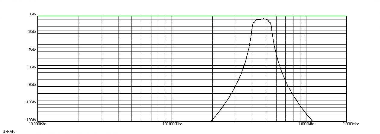
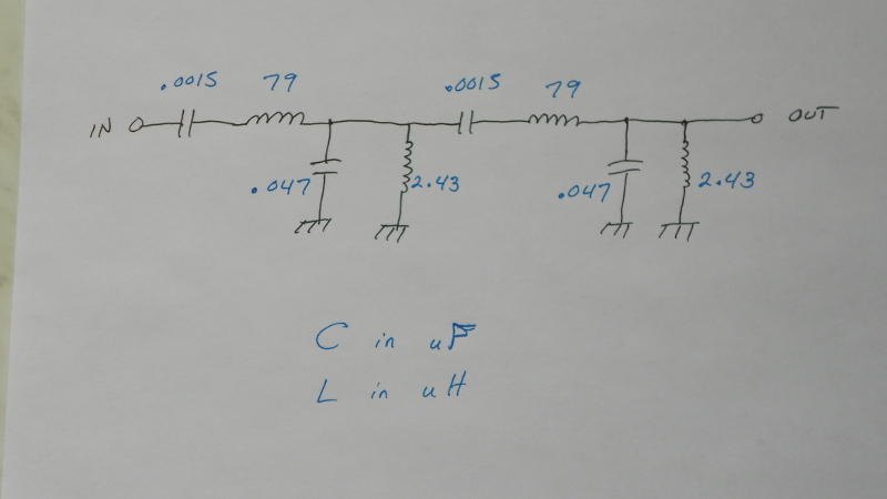
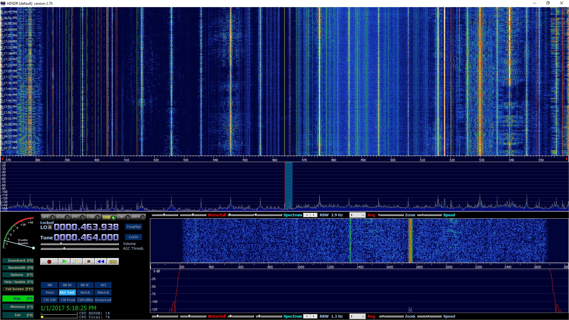
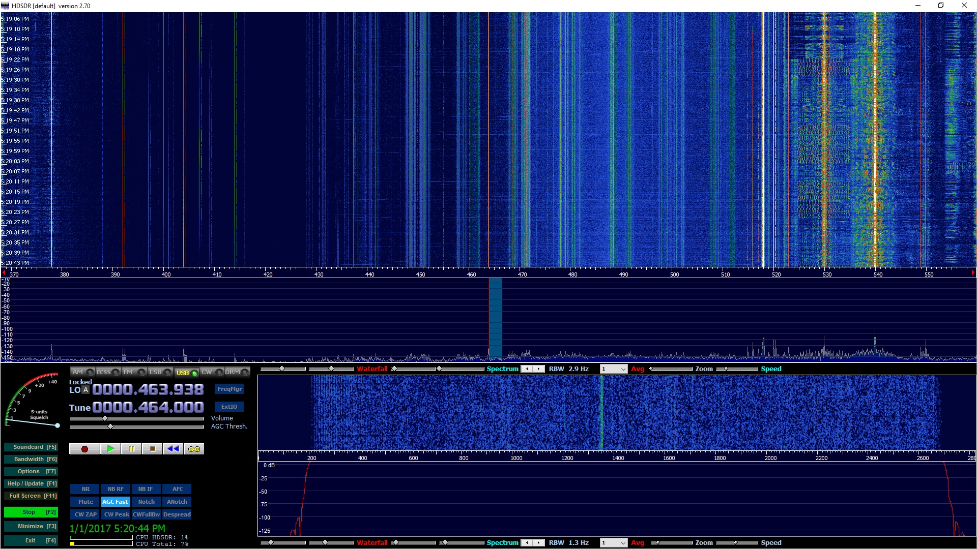
There is one major shortcoming of this unit as a 630 meter receiver, and that is its response to signals around the third harmonic of the LO. Remember that we are feeding the mixers with a square wave. Square waves are rich in odd harmonic content. I measured the LO third harmonic (1392 kHz) at 10 dB down from the fundamental 464 kHz. This is a problem since there are many strong signals around 1392 kHz in the middle of the medium wave broadcast band! The SoftRock input filter is only 40 dB down at this frequency. With the LO harmonic at -10 dB and the filter at -40 dB that puts these signals only 50 dB down from its response at the intended frequency, nowhere near enough. Without external filtering, the unwanted response to broadcast stations is a deal breaker at my station. With my outboard bandpass filter in addition to the SoftRock filter, response at 1392 kHz is 105 dB down, still not really enough as some of the stronger stations near the low end of the range (where filter attenuation is less) can still be heard. Bear in mind this is a known issue with simple SDRs of this type and this kit was never intended to be used as a receiver connected to an antenna. It was intended to connect to the IF in a conventional receiver where it would be afforded a great deal of protection by receiver tuned circuits and filters. The 630 meter band itself is “clean” when using my external bandpass filter in conjunction with the SoftRock’s internal filter, but not with the SoftRock alone. (Note: I measured the second harmonic of the LO at -32 dB. If I understand my theory correctly, and that is questionable, I believe the mixer will not respond to signals on even harmonics, making this a non issue. If I am wrong about that, then the second harmonic is also problematic)

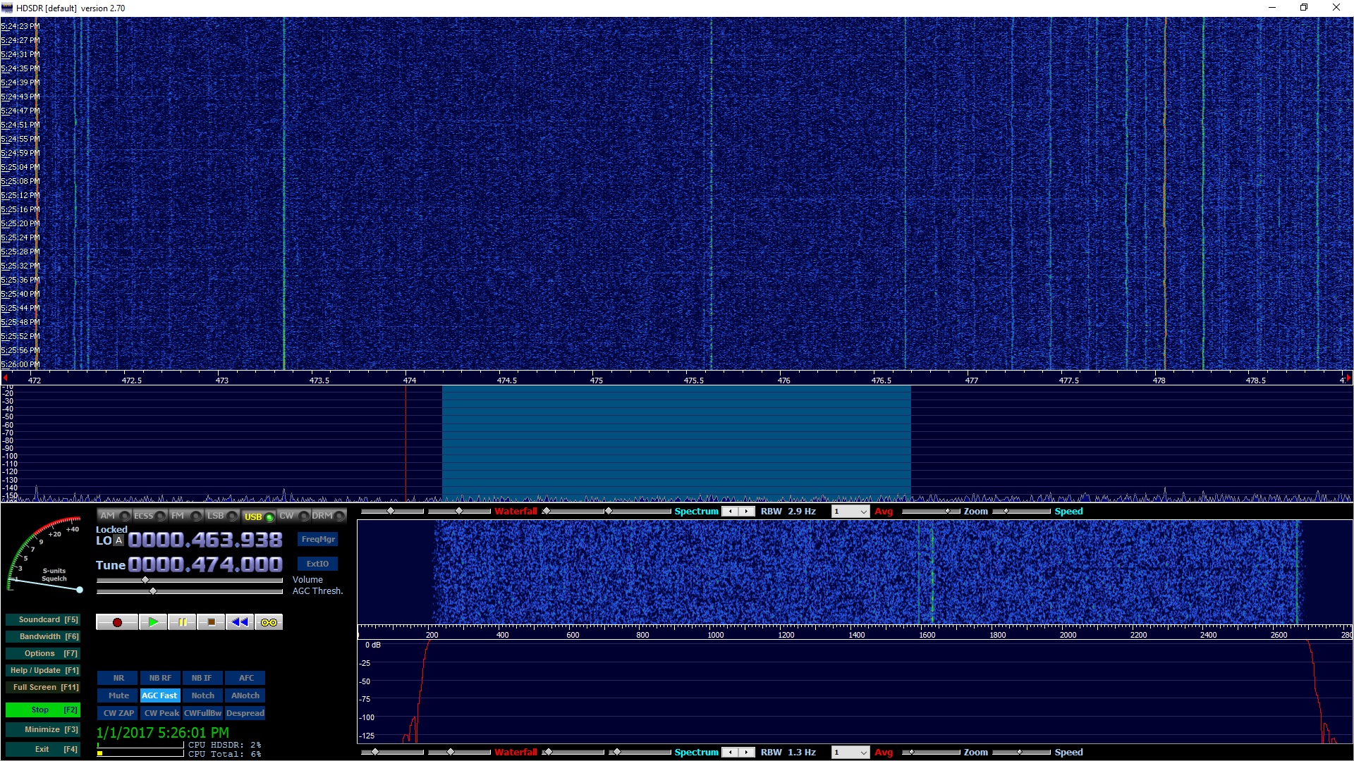
Despite most of my receive antennas being down due to storm damage during last night’s test run, the SoftRock did very well receiving 630 meter WSPR activity and one station that was sending “TEST TEST” on CW.

I find the SoftRock Lite II with 455 IF option to be a very promising receiver for 630 meter work but it will need additional band pass, low pass, or medium wave broadcast reject filtering. Without an outboard filter the test unit does a credible job receiving WSPR activity on 630 meters at times. At other times that segment is wiped out by unwanted response to broadcast stations. I strongly recommend that it be used with external filtering. The filter I am using can be built for about $10 (shipping not included) using all new parts. A well stocked junk box could reduce that. More on this to follow in a subsequent post.


The Dreaded SMD & Building a 630-Meter SDR

My new found interested in LF and MF is leading me in directions I didn’t expect. I have never been a fan of software defined radios; not because I have anything against the technology. I am well aware it is the future, if not the present of radio and the many advantages. My problem with SDRs for my own use is that if I have to do everything with a keyboard and mouse it diminishes the fun of operating. I am a knob twiddler. I like the old form of human to radio interface. Some years ago I operated from a multiop VHF contest station using an early SDR. I hated it, and even though I love VHF contesting, to be completely honest it just wasn’t fun with that radio. It wasn’t the performance or lack thereof. It was simply that I didn’t enjoy operating with a keyboard and mouse to control the radio. Of course a few modern SDRs have optional human interfaces using knobs, but they tend to be rather expensive.

On LF and MF, operating is very different. It often involves monitoring (or transmitting on, but without direct human interaction) a frequency for many hours, no settings needing to be changed. Thus, at least in the type of operations that are currently taking place there tends to be minimal interaction with the radio in any case. I also have not liked the fact that my only station transceiver has been tied up with this monitoring activity, keeping me from DX on the 160 through 2 meter bands. The apparent solution seemed to be an inexpensive SDR which could operate stand-alone.

I have had a fear of working with SMD parts since my first and only project involving them: the building of a simple OCXO kit a few years back. The OCXO worked when completed but I found soldering the parts difficult and the work was… shall we say… visually unappealing. I am a few years older now and my eyes are not great! I need prescription glasses to read anything, and a magnifier to read instructions on just about any household product these days. Would I be able to work with SMD? My interest in trying a very inexpensive SDR on LF and MF led me to seriously think about it. I spent many hours watching videos on how it is done, and many more lusting after SMD soldering and rework stations I can’t afford. But something unexpected happened. I began to feel a certain confidence that I could do this, and better than before.

I wanted to try a SoftRock Lite II receiver kit with the 455 kHz IF option – which should make a fine little SDR for 630 meters. If this worked out I had some ideas about modifying one for 2200 meters, following ideas and notes provided by Larry, W7IUV. While I was contemplating when I might afford to buy one (my budget was severely over-extended during recent VHF projects), Bill, KB1WEA decided to buy one for me to assemble on his behalf, evaluate and gain experience with. He must have believed me when I said I could do this! I was only half sure that I believed me!

The first thing I was going to need was a soldering iron with a much finer tip. All I had were some old Radio Shack 30 and 60 watt pencils and a 475 watt beast left over from the days when farmers soldered wash tubs and the like. I took an old, burned up tip for one of the 30 watt pencils and began to slowly reshape it on a stationary belt sander using a 320 grit belt. When I was satisfied with the more or less conical shape I hand sanded with 600 grit and then 1200 grit paper to obtain a smooth surface. It didn’t look too bad, but the proof would be in actually soldering SMD parts. I also purchased some .015″ diameter “Kester 44” solder and paste flux for the project. I would end up not using the paste flux.

It wasn’t long before the kit arrived. Looking at it I had a few pangs of doubt. The whole thing sure was small! Nevertheless, armed with my hand crafted soldering tip, lighted headband magnifier, tweezers and vise I was ready to dive right in. I read through the build notes (which more or less pass for assembly instructions), noting in particular the warning about tiny SMD capacitors flying out of tweezers never to be seen again. I knew this from personal experience with the OCXO kit. The first step of the build said “Install a SMD capacitor at…” Oh, great. Start me off easy, why don’t you? I fearlessly (that’s my story and I’m sticking to it) grabbed a part with the tweezers and almost immediately heard the dreaded “twink!” sound of its escape. My hearing is better than my eyes and I also heard it hit the hard laminate floor. I was going to find that thing if it took all day. With lighted magnifier on my head I proceeded to crawl ever so slowly around on hands and knees, head down to accommodate the six inch focal length, head scanning left to right looking for the part. My cat Boo came along and took quite an interest in this operation. If there was something worth finding on the floor he wanted first dibs on it! It might be a tasty morsel or a new toy. I wish I had a video of this. He commenced doing exactly what I was: slowly inching forward, eyes down, head scanning left to right. Side by side we worked our way along a swath of floor. An hour later I found the escaped capacitor. Eureka! Gotcha, ya little bugger! Boo had become bored or convinced that this theory of there being something on the floor to find was all in my imagination. He was now sound asleep in another room. I did find the part in a spot I had seen him pause to sniff and examine closely twice. Perhaps he had seen it and decided this thing was far too small to be of any use.

Assembly proceeded well after that. I modified my approach to dealing with the SMD parts. Instead of picking them up with tweezers for transport to the board, I placed them on the board with my fingers, used the tweezers to gently nudge them to and fro. Once happy with alignment, I held them down with pressure from the tweezers while tacking one end or one pin. This worked much better for me. I was concerned about ESD on the sensitive chips, but I used my tried and true completely improper methods: boil water to create humidity, wear an anti-static wrist strap grounded to the PCB and to the soldering iron with a clip lead! It looks ridiculous but I have had pretty good luck with this method. I make no claims whatsoever that my SMD soldering is professional quality. It isn’t. But it seems to get the job done and believe me it looks a lot better than my work on that OCXO!

In order to evaluate performance in a typical use scenario and to avoid damaging the tiny receiver, I packaged it in a Hammond diecast box. I used a BNC socket for the antenna and coaxial jack for DC power. I didn’t have any TRS (stereo) audio connectors so I cheated and just drilled a hole in the box to run the audio cable through. It can always be changed later.

All in all, assembling this kit was a pleasure. By the end I was actually finding it more pleasurable to work with SMD parts than all that tedious lead bending and cutting with the through hole parts! The most tedious part of the build was winding and installing the toroidal input transformer.


Comments on the Jackson Harbor press LF Converter

After discovering my Yaesu FT-2000 receiver sensitivity is -75 dBm at 137 kHz, I needed something better to receive the 2200 meter band. The Jackson Harbor Press LF Converter was suggested. I was sent a kit by a friend. It is the previous version which uses FT-37-61 cores for the inductors in the low pass filter.

Assembly was quick and easy, taking about an hour. I modified the low pass filter slightly since I wanted to concentrate on 2200 meters and have maximum rejection of the medium wave broadcast band. I mounted mine in a Hammond die cast box with BNC connectors for RF input/output and a coaxial power jack for 13.8VDC.

My signal generator minimum output is -137 dBm. This produced a very clear tone, so I estimate the converter MDS is at least -140 dBm. Next I measure IF leakthrough and found it to be on the order of 50 dB. I could detect a tone at a level of -90 dBm. This isn’t great, but noise on LF would mask another 30 dB or so of signal. In actual operation for about one week monitoring all night (half of this time with a 10 MHz IF, the other half 4 MHz) I have not detected any actual problems with signals on the IF frequency being heard.

That brings me to the subject of LO drift. There is less drift with the 4 MHz LO frequency, so that is the only one I made extensive measurements on. There is enough IF signal present at the converter output to amplify with one of my 2N5109 preamps and feed to my HP 5335A counter. It is winter here so the temperature in my shack varies slightly as the furnace cycles on and off. With the converter sitting on top of my rack mounted computer which gives off some heat I found a cyclic drift of between 0.8 and 1.3 Hertz after looking at several cycles. Each cycle was slightly unique. I lowered the thermostat by 6 degrees F and after allowing a few cycles for things to settle I looked at the drift again. It was about the same as before but everything had shifted up approximately 5 Hertz. After moving the converter to a location not influenced by heat from the computer, similar measurements were obtained. Overall the LO shifted down a couple of Hertz but the 0.8 to 1.2 Hz cyclic variation as the furnace cycled on and off remained mostly unchanged. I replaced the small trimmer capacitor with a fixed 22 pf NP0 ceramic and a 1-10 pf piston trimmer. This did not measurably improve the situation.

I find the converter very adequate for general LF listening and acceptable for casual WSPR monitoring on 137 kHz. The serious WSPR reporter will probably want better frequency accuracy than this converter can provide. For QRSS and DFCW the converter is not acceptable. This amount of drift will cause serious problems for those modes.

It is possible the LO could be stabilized with a crystal heater but since my FT-2000 has too much drift to be useful even if the converter were perfect I am not going to pursue that. Another option would be to use a precision OCXO in place of the onboard LO. Suitable units can be found on eBay for around $50.

Adding 630 and 2200 Meters to the MFJ-259B

As I began to explore the world of MF and LF I realized it wouldn’t be long before the need to assess antenna possibilities arose. Specifically I would be needing to know whether it was going to be possible to construct antennas for these bands with the space and supports I have available, and without killing other bands. I read this article by KB5NJD discussing his 630 meter modification of the MFJ-259B based on earlier work by KL7UW. Although the 259B has some limitations (and even more so when operating on frequencies it was never designed for), this caught my eye because I own one. Even with the limitations it should be plenty good enough to answer my question about antenna potential. I soon learned that John, KB5NJD had also got his working on 2200 meters.

The earlier work was based on experimental use of junk box ferrite cores. I had no ferrite cores in my junk box and no real idea what I needed. I don’t think it is unreasonable to believe others may be in the same situation. I made it my goal to come up with a method which could easily be duplicated with off the shelf parts. In order to accomplish this, I initially purchased several different cores of different material to experiment with. This is exactly the kind of expense I was hoping to spare others by coming up with a standard “recipe” that could be followed for the modification. The resulting modification uses two FT-37-W ferrite cores and one DP3T switch.

The 630 meter inductor consists of 17 turns #24 wire on one FT-37-W core. The tuning range I obtained is 280 to 590 kHz. The 2200 meter coil is 45 turns of #30 wire on one FT-37-W core, which tunes 105 to 220 kHz. These are wired with a DP3T switch so that one throw is normal operation of the MFJ-259B on its original lowest range, 1.7 to 4 MHz. Position two is the 630 meter range, and position three is the 2200 meter range.

Modification is simple. Open up the unit, remove the battery compartment and locate the band switch. With the analyzer upside down and the bottom facing you, it is on the lower left portion of the printed circuit board.

We are going to need to cut one circuit trace connected to the band switch. The detailed photo shows its location. This is the trace that connects the 1.7 to 4 MHz range coil when the band switch is in that position. I used a razor knife to cut the trace. The “common” switch contacts wire to the solder connection at each end of the cut trace. One output of the switch is shorted with a piece of wire so that when the switch is in that position these two points are connected, just as they were with the original circuit trace. Another pair of output contacts has the 630 meter inductor connected across it, and the last has the 2200 meter inductor similarly connected. I drilled a hole in the bottom of the case to mount the switch. Remember the batter compartment! I forgot about the space it takes up and the first hole I drilled didn’t leave room for the switch when the batter compartment is in. I had to drill a second hole, but I managed to hide this fact with labels I made for the inside and outside.

This is the inside after the modification is complete.


The outside after completing the modification.


As mentioned earlier, this has some limits. Don’t expect the R and X values to be exact on the new bands. For that matter, don’t expect them to be exact on any band! This is not a high end instrument. It is likely that the presence of reactance will affect resistance readings and vice versa, but if one first tuned out the reactance, then deals with resistance this should get you close enough for a lot of projects. Below is a table of  measurements I made using resistors with no reactance present.

RESISTOR     160m R   160m X   630m R   630m X   2200m R   2200m X
-------------------------------------------------------------------
0.1 ohm      0        0        0        #        0         #
1 ohm        1        0        1        0        1         0
10 ohm       10       0        10       0        9         0
51 ohm       51       0        51       4        48        13
50 TERM      49       1        49       4        47        12
100 ohm      99       6        100      0        91        28
240 ohm      246      0        251      0        180       110
510 ohm      505      165/0*   529      0        207       270/0*

#   No reading displayed
*   alternating between two readings shown
50 TERM was a precision 50 ohm termination for reference

At a later date I hope to do some testing with known amounts of reactance present and see how this affects things. This isn’t as simple as the resistance tests and will take a considerable amount of time.


In Pursuit of 2200 Meters: My Receiver Won’t Do It

Since my participation in Crossband Night several weeks ago I have been getting more and more interested in 630 meters. I have been listening to the WSPR beaconing stations most nights, and have found it is relatively easy to hear Europe and Hawaii when conditions are good. But, as always I am more attracted to the extreme. 2200 meters is the extreme!

I have attempted to hear stations on 2200 several times. It took two weeks to realize any success at all. I was barely able to detect signals from WD2XES and VO1NA on “below the noise” digital modes. It was obvious my system was deaf, but I blamed it on the antennas. After all, what could you expect from a “Beverage” that is less than 0.1 wavelength long? When I finally did hear stations, it was using an 80 meter inverted V. I did realize, however, that there were some issues with the Beverages not related to length. The transformers were not designed for this low frequency and probably had some loss if they worked at all. Later analysis with assistance from WA3TTS showed them to be about -3 dB. That’s not too bad. I also feed 26 volts DC down the coax to each Beverage feed box to power the direction switching relay. I use bidirectional Beverages made from WD-1A field phone wire. The chokes in the bias tees, it turns out, were 140 uH which barely offered 120 ohms of inductive reactance; clearly not enough. The capacitors in the bias tees were 0.1 uF or 12 ohms capacitive reactance; not too bad but it could stand some improvement.

After modifying the bias tees by adding 1 uF capacitors in parallel with the 0.1 uF and swapping out the chokes for some having almost 6 mH of inductance I found the system was still completely deaf. I built a W1VD preamp which measured 22 dB gain. That brought medium wave broadcast signals up to a level my receiver couldn’t handle. I had IMD products and garbage everywhere! Next I built a bandpass filter which rolls off more than 60 dB by the time it reaches 600 kHz and continues to roll of sharply above that. Now the IMD was gone with the preamp in line. For the first time I could hear some NDBs (nondirectional beacons used at airports for navigation) around 200 kHz, but still nothing in the 2200 meter band at 135.7 to 137.8 kHz.

At this point I began to sense my receiver itself (an FT-2000) might not be up to par on sensitivity that low in frequency. I had already discovered the built in 10 and 20 dB preamps acted like attenuators at this frequency! How to measure it? My Agilent E8285A test set is not specified to work below 400 kHz. While its signal generator will go down to 100 kHz I feared the level would be far from calibrated. I had a recently calibrated HP 3325B but its minimum output level is 0.001 volt peak-to-peak or -56 dBm; far too much to be of use in checking receiver sensitivity. Nevertheless I tried it and found the signal much weaker at 2200 meters than it was at 630 meters or 160 meters. At that point I grabbed every type N attenuator I had and started stringing them together. I realized very quickly that the receiver MDS (minimum discernible signal) was no better than about -75 dBm at 136 kHz! Wow, that is bad! Even my W1VD preamp would only bring it to -97 dBm, still deaf as a post!

Then an idea dawned in the dim recesses of my mind. I had a HP 1980B oscilloscope which I trusted to be in calibration at least for voltage measurements. I decided to use the scope to check the output of the Agilent service monitor at 160, 630, and 2200 meters. Lo and behold, I found it holds up pretty well, the output increasing only a couple of dB at 100 kHz. I then proceeded to measure receiver MDS at 1810, 475, and 136 kHz. On 1810 it was quite a bit better than -137 dBm, which is the lower limit for the Agilent. I didn’t bother using attenuators to find out just what it really is. Suffice to say it’s around -140 dBm. At 475 kHz it is -130 dBm or about 10 dB worse but still not too bad. My earlier test at 136 kHz was confirmed: -75 dBm. Wow. Just wow.

At this point I know the FT-2000 is useless for 2200 meter receiving. I will try something else. Stay tuned!