
As I began to explore the world of MF and LF I realized it wouldn’t be long before the need to assess antenna possibilities arose. Specifically I would be needing to know whether it was going to be possible to construct antennas for these bands with the space and supports I have available, and without killing other bands. I read this article by KB5NJD discussing his 630 meter modification of the MFJ-259B based on earlier work by KL7UW. Although the 259B has some limitations (and even more so when operating on frequencies it was never designed for), this caught my eye because I own one. Even with the limitations it should be plenty good enough to answer my question about antenna potential. I soon learned that John, KB5NJD had also got his working on 2200 meters.
The earlier work was based on experimental use of junk box ferrite cores. I had no ferrite cores in my junk box and no real idea what I needed. I don’t think it is unreasonable to believe others may be in the same situation. I made it my goal to come up with a method which could easily be duplicated with off the shelf parts. In order to accomplish this, I initially purchased several different cores of different material to experiment with. This is exactly the kind of expense I was hoping to spare others by coming up with a standard “recipe” that could be followed for the modification. The resulting modification uses two FT-37-W ferrite cores and one DP3T switch.
The 630 meter inductor consists of 17 turns #24 wire on one FT-37-W core. The tuning range I obtained is 280 to 590 kHz. The 2200 meter coil is 45 turns of #30 wire on one FT-37-W core, which tunes 105 to 220 kHz. These are wired with a DP3T switch so that one throw is normal operation of the MFJ-259B on its original lowest range, 1.7 to 4 MHz. Position two is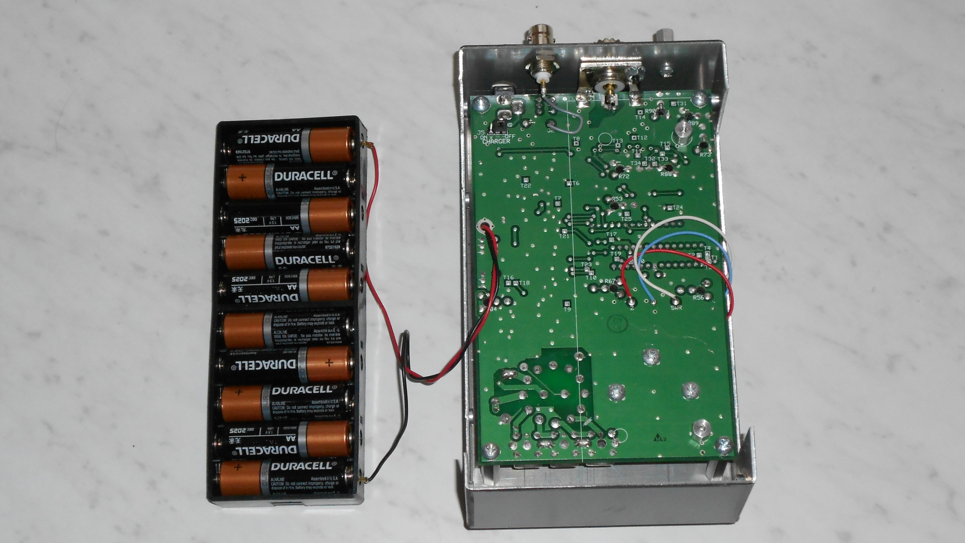 the 630 meter range, and position three is the 2200 meter range.
Modification is simple. Open up the unit, remove the battery compartment and locate the band switch. With the analyzer upside down and the bottom facing you, it is on the lower left portion of the printed circuit boa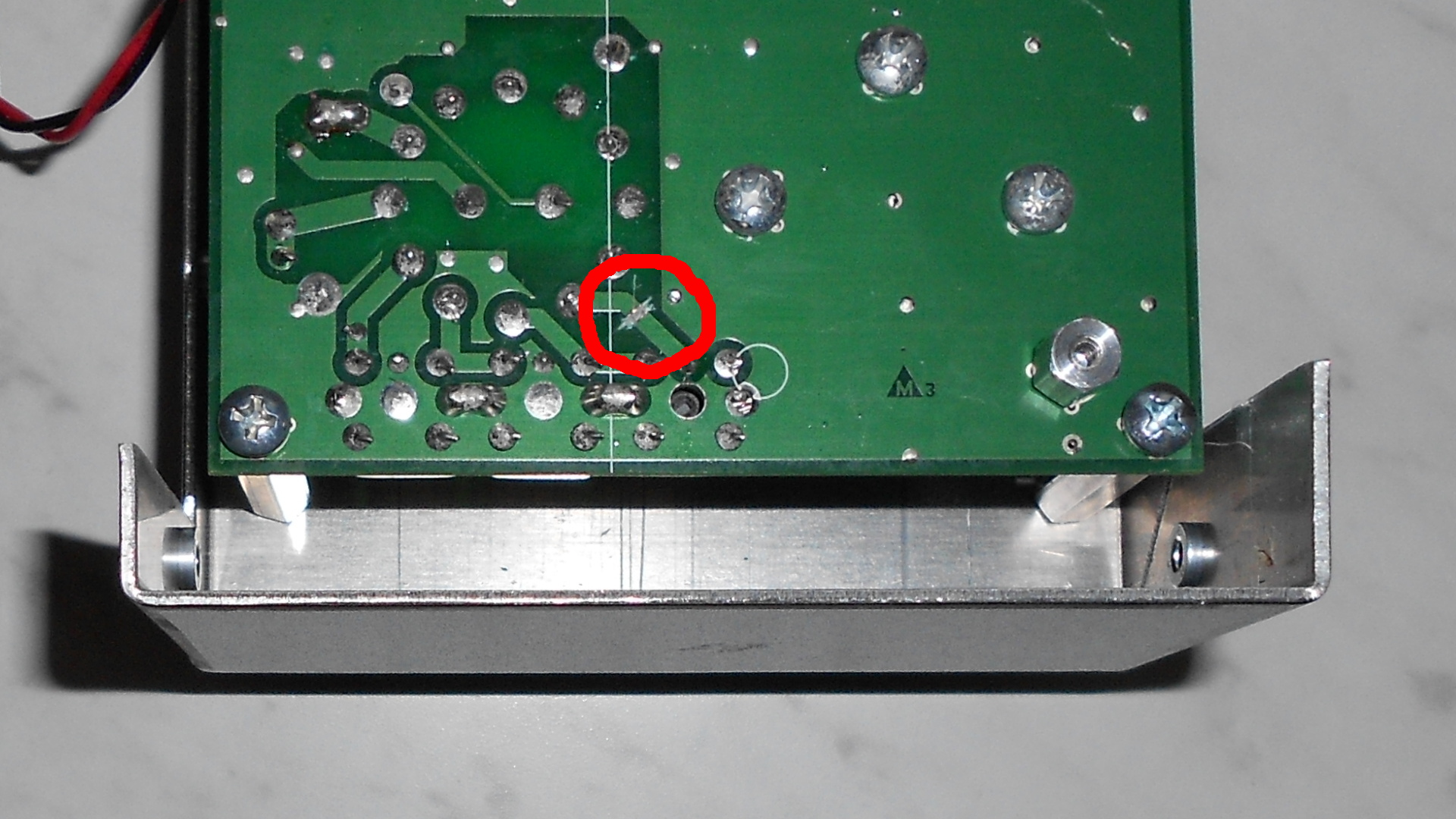 rd.
rd.
We are going to need to cut one circuit trace connected to the band switch. The detailed photo shows its location. This is the trace that connects the 1.7 to 4 MHz range coil when the band switch is in that position. I used a razor knife to cut the trace. The “common” switch contacts wire to the solder connection at each end of the cut trace. One output of the switch is shorted with a piece of wire so that when the switch is in that position these two points are connected, just as they were with the original circuit trace. Another pair of output contacts has the 630 meter inductor connected across it, and the last has the 2200 meter inductor similarly connected. I drilled a hole in the bottom of the case to mount the switch. Remember the batter compartment! I forgot about the space it takes up and the first hole I drilled didn’t leave room for the switch when the batter compartment is in. I had to drill a second hole, but I managed to hide this fact with labels I made for the inside and outside.
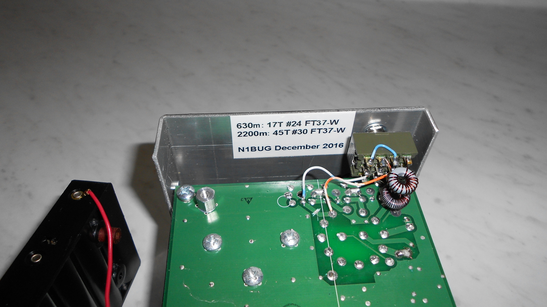 This is the inside after the modification is complete.
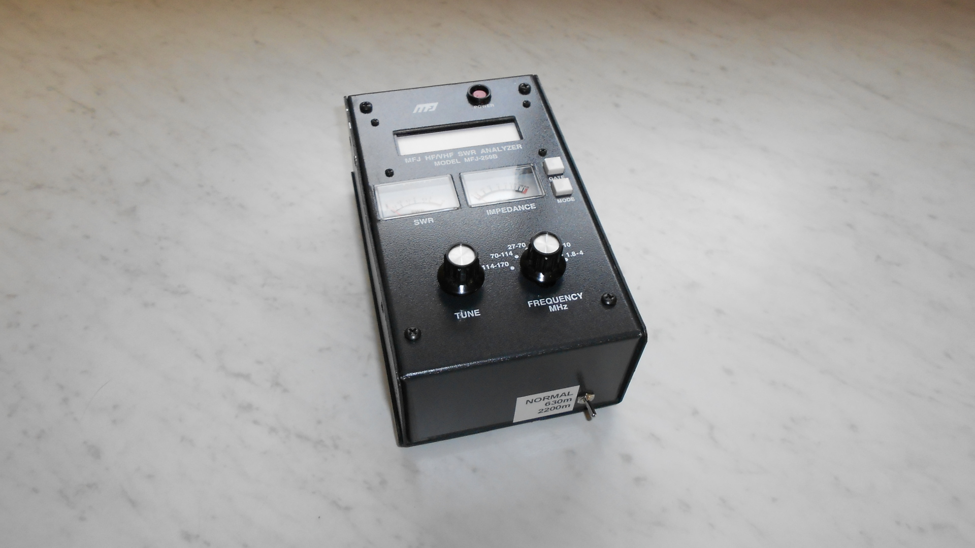 The outside after completing the modification.
As mentioned earlier, this has some limits. Don’t expect the R and X values to be exact on the new bands. For that matter, don’t expect them to be exact on any band! This is not a high end instrument. It is likely that the presence of reactance will affect resistance readings and vice versa, but if one first tuned out the reactance, then deals with resistance this should get you close enough for a lot of projects. Below is a table of measurements I made using resistors with no reactance present.
RESISTOR     160m R   160m X   630m R   630m X   2200m R   2200m X
-------------------------------------------------------------------
0.1 ohm      0        0        0        #        0         #
1 ohm        1        0        1        0        1         0
10 ohm       10       0        10       0        9         0
51 ohm       51       0        51       4        48        13
50 TERM      49       1        49       4        47        12
100 ohm      99       6        100      0        91        28
240 ohm      246      0        251      0        180       110
510 ohm      505      165/0*   529      0        207       270/0*

#   No reading displayed
*   alternating between two readings shown
50 TERM was a precision 50 ohm termination for reference
At a later date I hope to do some testing with known amounts of reactance present and see how this affects things. This isn’t as simple as the resistance tests and will take a considerable amount of time.