
My new found interested in LF and MF is leading me in directions I didn’t expect. I have never been a fan of software defined radios; not because I have anything against the technology. I am well aware it is the future, if not the present of radio and the many advantages. My problem with SDRs for my own use is that if I have to do everything with a keyboard and mouse it diminishes the fun of operating. I am a knob twiddler. I like the old form of human to radio interface. Some years ago I operated from a multiop VHF contest station using an early SDR. I hated it, and even though I love VHF contesting, to be completely honest it just wasn’t fun with that radio. It wasn’t the performance or lack thereof. It was simply that I didn’t enjoy operating with a keyboard and mouse to control the radio. Of course a few modern SDRs have optional human interfaces using knobs, but they tend to be rather expensive.
On LF and MF, operating is very different. It often involves monitoring (or transmitting on, but without direct human interaction) a frequency for many hours, no settings needing to be changed. Thus, at least in the type of operations that are currently taking place there tends to be minimal interaction with the radio in any case. I also have not liked the fact that my only station transceiver has been tied up with this monitoring activity, keeping me from DX on the 160 through 2 meter bands. The apparent solution seemed to be an inexpensive SDR which could operate stand-alone.
I have had a fear of working with SMD parts since my first and only project involving them: the building of a simple OCXO kit a few years back. The OCXO worked when completed but I found soldering the parts difficult and the work was… shall we say… visually unappealing. I am a few years older now and my eyes are not great! I need prescription glasses to read anything, and a magnifier to read instructions on just about any household product these days. Would I be able to work with SMD? My interest in trying a very inexpensive SDR on LF and MF led me to seriously think about it. I spent many hours watching videos on how it is done, and many more lusting after SMD soldering and rework stations I can’t afford. But something unexpected happened. I began to feel a certain confidence that I could do this, and better than before.
I wanted to try a SoftRock Lite II receiver kit with the 455 kHz IF option – which should make a fine little SDR for 630 meters. If this worked out I had some ideas about modifying one for 2200 meters, following ideas and notes provided by Larry, W7IUV. While I was contemplating when I might afford to buy one (my budget was severely over-extended during recent VHF projects), Bill, KB1WEA decided to buy one for me to assemble on his behalf, evaluate and gain experience with. He must have believed me when I said I could do this! I was only half sure that I believed me!
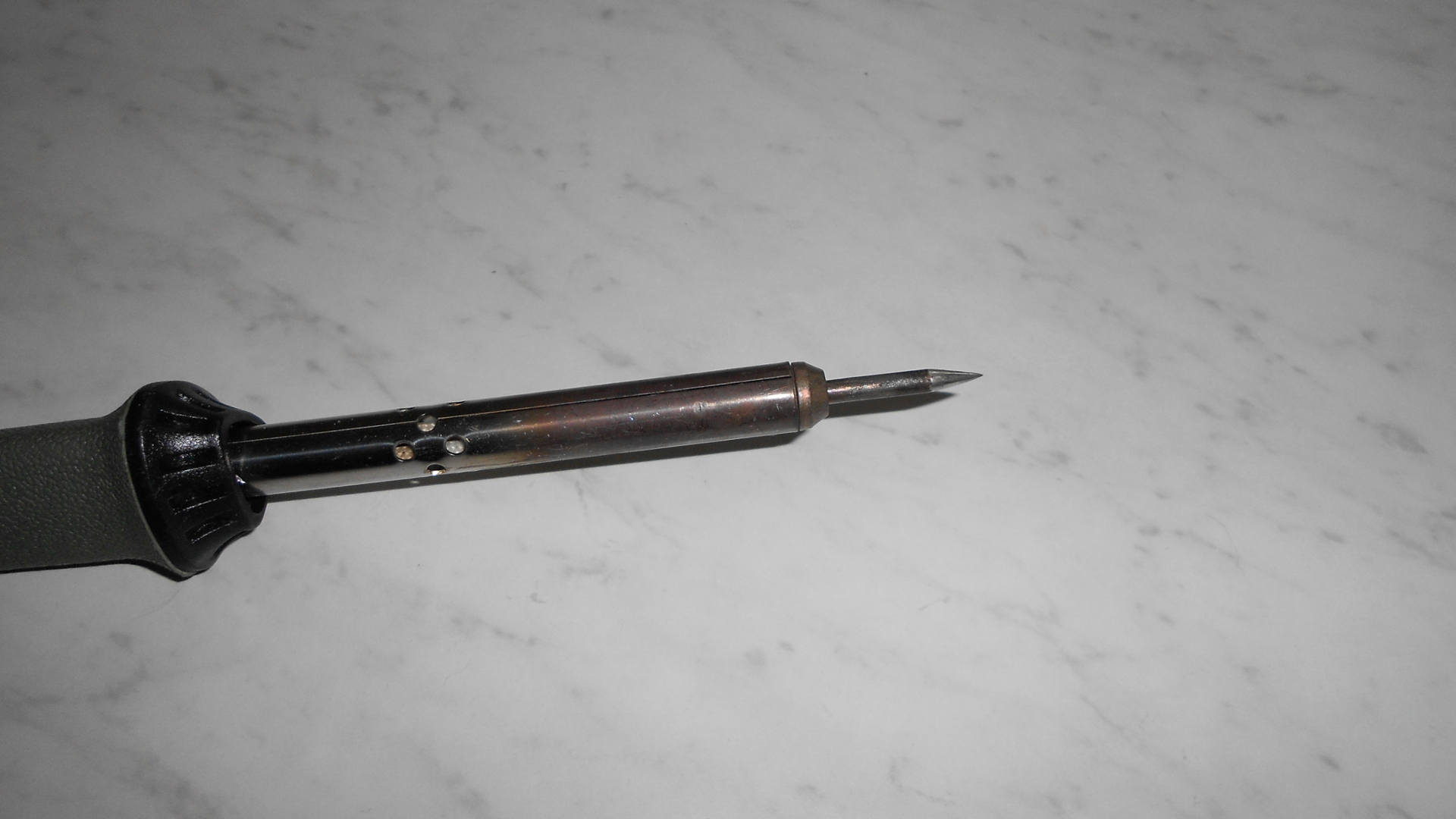 The first thing I was going to need was a soldering iron with a much finer tip. All I had were some old Radio Shack 30 and 60 watt pencils and a 475 watt beast left over from the days when farmers soldered wash tubs and the like. I took an old, burned up tip for one of the 30 watt pencils and began to slowly reshape it on a stationary belt sander using a 320 grit belt. When I was satisfied with the more or less conical shape I hand sanded with 600 grit and then 1200 grit paper to obtain a smooth surface. It didn’t look too bad, but the proof would be in actually soldering SMD parts. I also purchased some .015″ diameter “Kester 44” solder and paste flux for the project. I would end up not using the paste flux.
It wasn’t long before the kit arrived. Looking at it I had a few pangs of doubt. The whole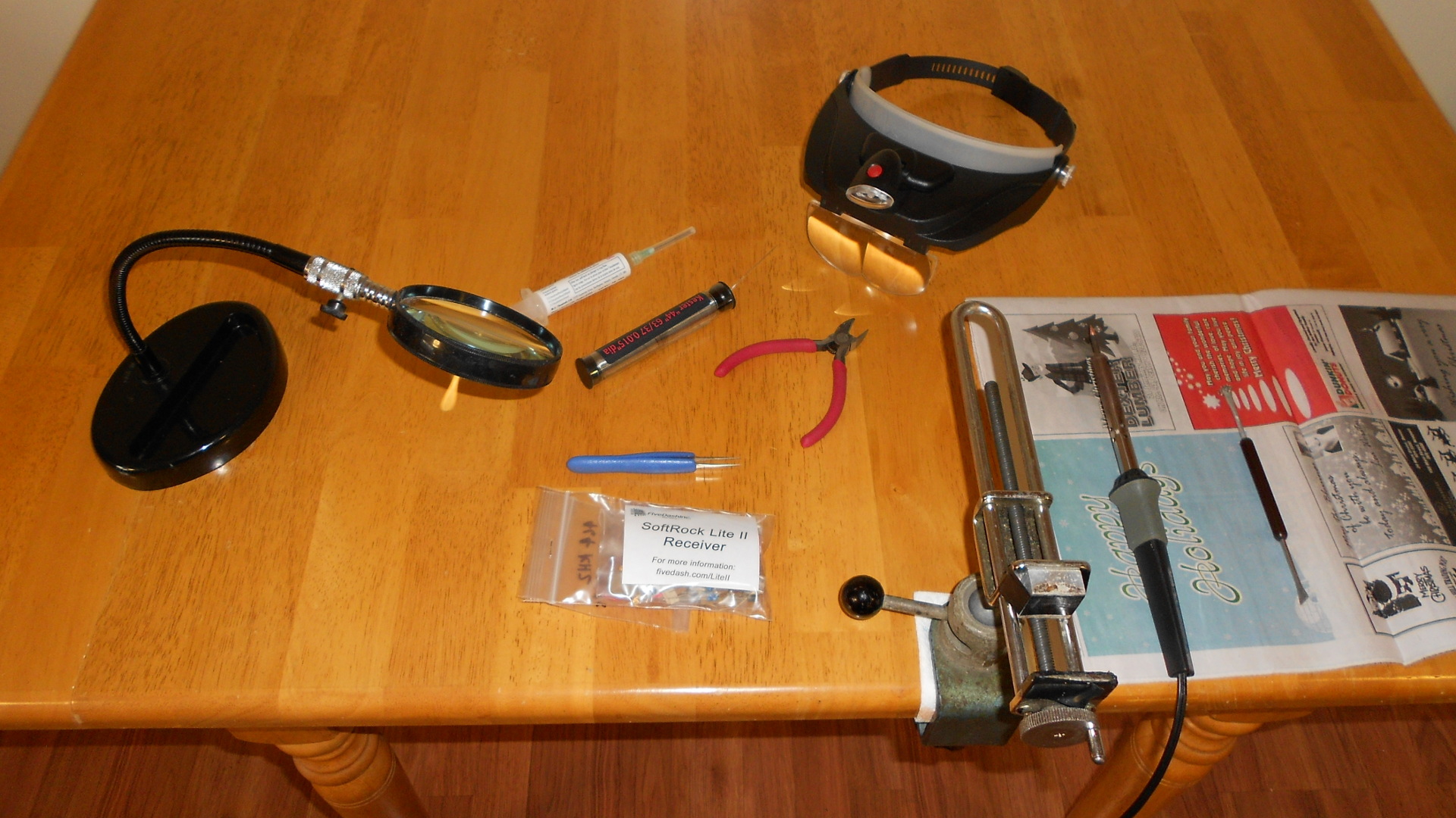 thing sure was small! Nevertheless, armed with my hand crafted soldering tip, lighted headband magnifier, tweezers and vise I was ready to dive right in. I read through the build notes (which more or less pass for assembly instructions), noting in particular the warning about tiny SMD capacitors flying out of tweezers never to be seen again. I knew this from personal experience with the OCXO kit. The first step of the build said “Install a SMD capacitor at…” Oh, great. Start me off easy, why don’t you? I fearlessly (that’s my story and I’m sticking to it) grabbed a part with the tweezers and almost immediately heard the dreaded “twink!” sound of its escape. My hearing is better than my eyes and I also heard it hit the hard laminate floor. I was going to find that thing if it took all day. With lighted magnifier on my head I proceeded to crawl ever so slowly around on hands and knees, head down to accommodate the six inch focal length, head scanning left to right looking for the part. My cat Boo came along and took quite an interest in this operation. If there was something worth finding on the floor he wanted first dibs on it! It might be a tasty morsel or a new toy. I wish I had a video of this. He commenced doing exactly what I was: slowly inching forward, eyes down, head scanning left to right. Side by side we worked our way along a swath of floor. An hour later I found the escaped capacitor. Eureka! Gotcha, ya little bugger! Boo had become bored or convinced that this theory of there being something on the floor to find was all in my imagination. He was now sound asleep in another room. I did find the part in a spot I had seen him pause to sniff and examine closely twice. Perhaps he had seen it and decided this thing was far too small to be of any use.
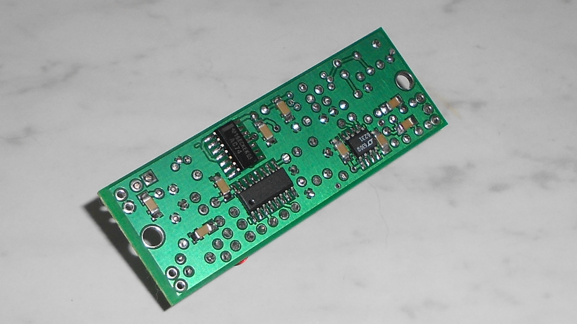 Assembly proceeded well after that. I modified my approach to dealing with the SMD parts. Instead of picking them up with tweezers for transport to the board, I placed them on the board with my fingers, used the tweezers to gently nudge them to and fro. Once happy with alignment, I held them down with pressure from the tweezers while tacking one end or one pin. This worked much better for me. I was concerned about ESD on the sensitive chips, but I used my tried and true completely improper methods: boil water to create humidity, wear an anti-static wrist strap grounded to the PCB and to the soldering iron with a clip lead! It looks ridiculous but I have had pretty good luck with this method. I make no claims whatsoever that my SMD soldering is professional quality. It isn’t. But it seems to get the job done and believe me it looks a lot better than my work on that OCXO!
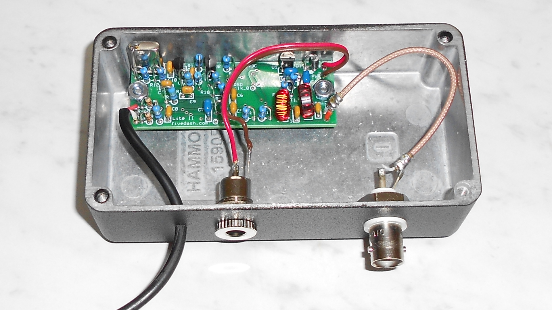 In order to evaluate performance in a typical use scenario and to avoid damaging the tiny receiver, I packaged it in a Hammond diecast box. I used a BNC socket for the antenna and coaxial jack for DC power. I didn’t have any TRS (stereo) audio connectors so I cheated and just drilled a hole in the box to run the audio cable through. It can always be changed later.
All in all, assembling this kit was a pleasure. By the end I was actually finding it more pleasurable to work with SMD parts than all that tedious lead bending and cutting with the through hole parts! The most tedious part of the build was winding and installing the toroidal input transformer.