I had long since given up believing I would ever see a VHF/UHF tropo opening to the midwest. Tropo in this part of Maine is exceedingly rare. It seems like everyone gets more of it than we do. Southern New England sees several good tropo events every year, both to the midwest and down the coast. Our Canadian neighbors to the east and southeast get openings down the coast a few times a year. We, however, see many years with nothing beyond every day “brute force” troposcatter range of roughly 500 miles. Since I got on VHF in 1986 I have seen no more than five tropo events that reached beyond that. Every one of them was down the coast to extreme eastern Virginia and possibly extreme eastern North Carolina. Without looking back through paper logs I am uncertain what my best tropo DX was, but I believe it was under or around 800 miles. I am positive there was nothing over 850 miles.
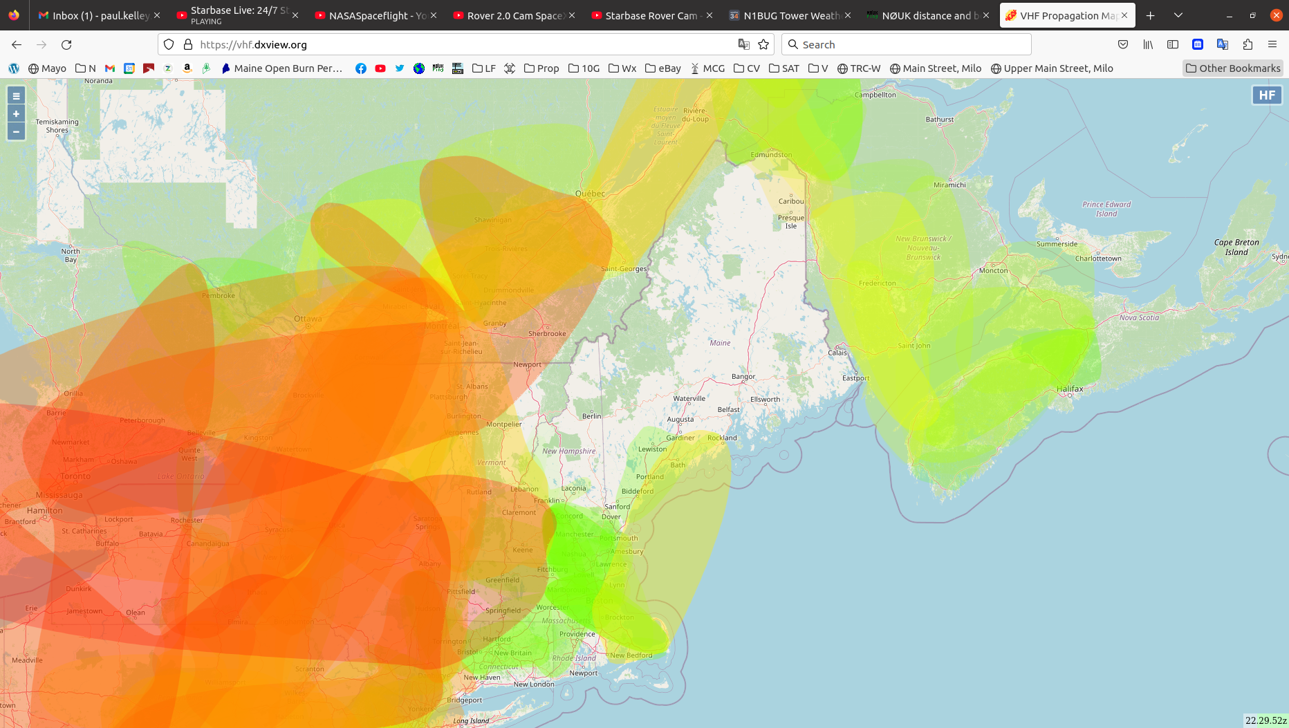
The event that occurred on September 2, 2023 was quite a shock! On the afternoon of September 1 I had checked 10 GHz and discovered N1JEZ beacon, 195 miles away, was in weakly as it had been for several days back in July. I didn’t think much of it at the time, but as I continued to monitor it got stronger and I realized this was a real tropo event for short distances on microwaves. There was nothing on VHF however. Here is an audio recording of N1JEZ/b on 10 GHz. This was not at the peak time but solid copy at 10 to 15 dB out of the noise. In the center section of the clip I switched in the audio peak filter to enhance it a bit more.
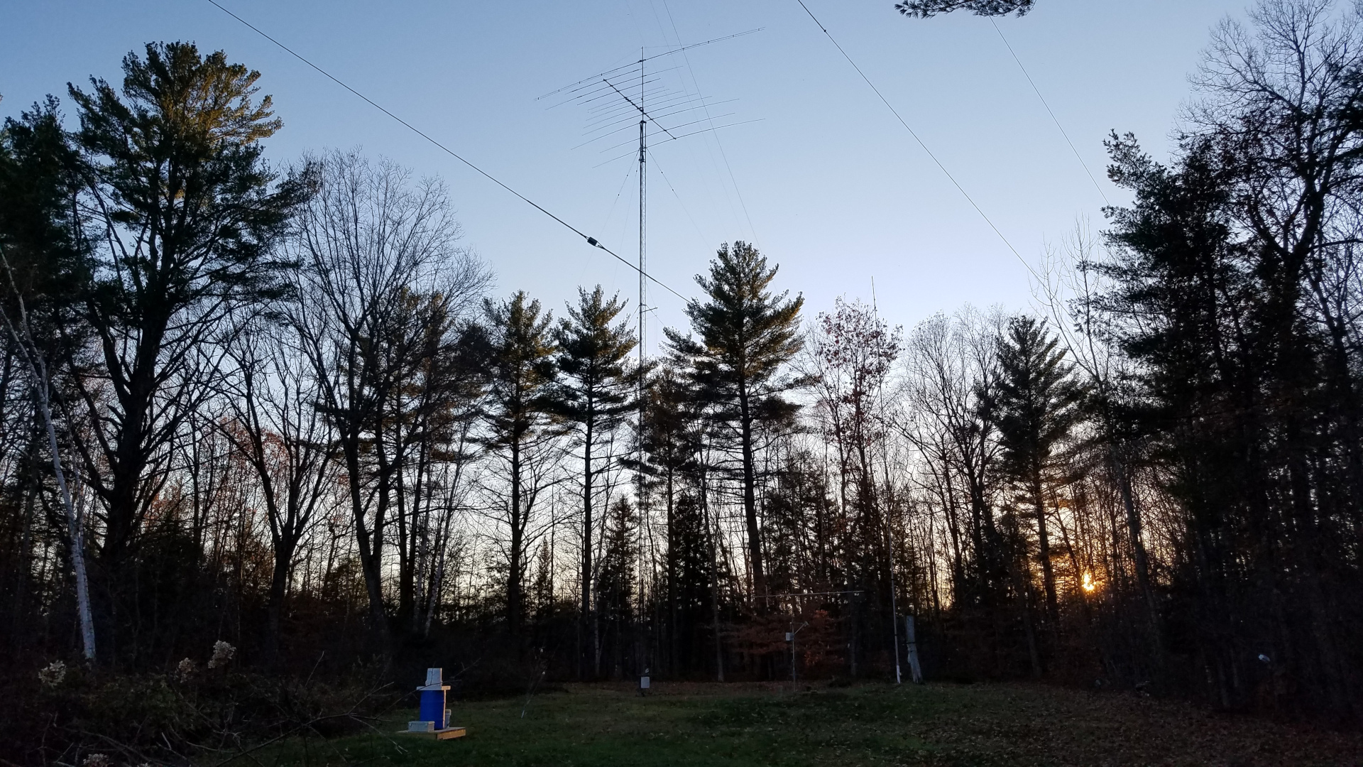
The situation while N1JEZ/b on 10 GHz was solid copy. Nothing evident in my area and I had no sign of DX on VHF or UHF.
Curious to see what would happen, I left the receiver monitoring when I went to bed. I was awakened at 3:00 in the morning by a screaming loud N1JEZ beacon. By the time I got myself functioning and into the shack it had already dropped in strength significantly, but a look at the APRS propagation map showed very strong tropo to my west and some paths passing by me to my northwest. I began monitoring and calling on 2 meter FT8. I could hardly believe it when I started decoding WB9ENB in EN71, a distance of over 800 miles. I soon worked him followed by KD2CDV in FN03 at 503 miles. Wow! Tropo to the midwest! This was a first for me!
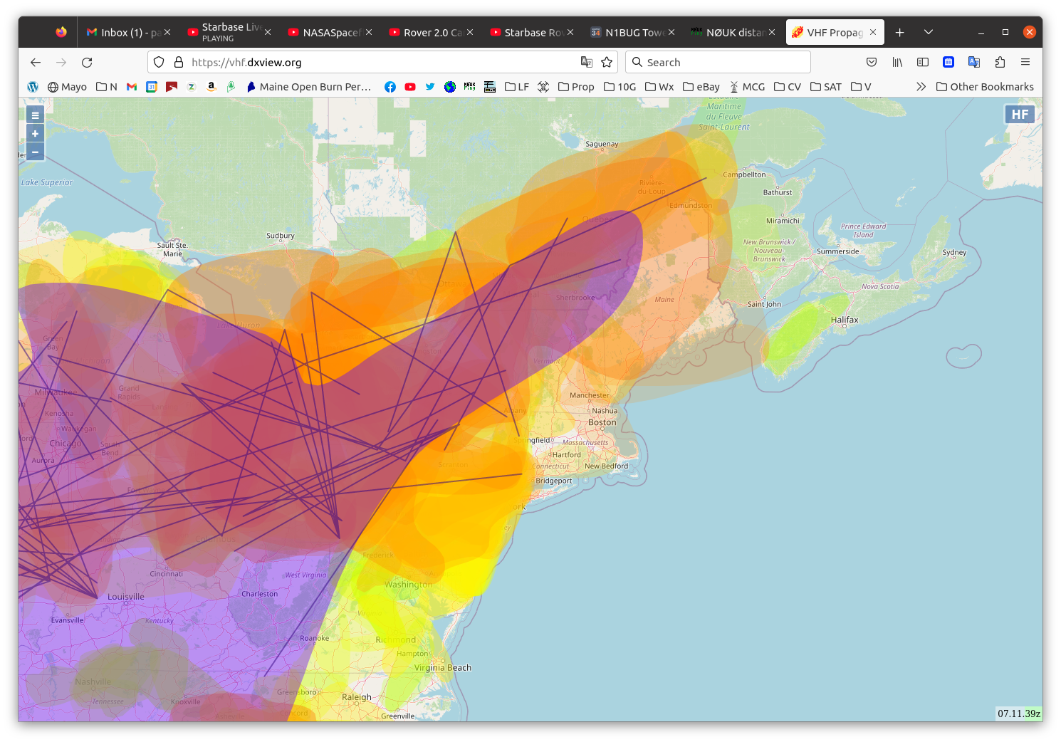
APRS map of the tropo opening shortly before I started hearing VHF DX. I am in the orange area about 70 miles east of the purple area extending across northwestern Maine.
Not long after that I worked W9FF in EN40tf, a distance of 1136 miles! Not only was I working the midwest, but I had just smashed by personal best tropo distance record by a few hundred miles! W9FF was so strong that I asked him on ON4KST chat if he could possibly work me on CW to fulfill a long time dream of making a tropo contact at that distance on a human decodable mode. Roger kindly agreed to take time out from working others to do so and we soon had a CW QSO with 559 reports exchanged both ways. I am eternally grateful for this kindness. That was a huge thrill for me! Here is an audio recording of W9FF on CW.
After a few more moderate distance QSOs on 144 and 222 MHz, VA3IKE tried me on 432. I only have 25 watts on that band and it was not getting the job done. We moved to Q65 mode to dig deeper into the noise and soon had completed a QSO of 716 miles. I thought that was pretty amazing under the circumstances. Little did I know what was about to happen.
After completing a 432 FT8 QSO with VE3DS, N0PB called me. I thought there was no way he could be hearing me at 1239 miles but I responded and it was a very easy FT8 QSO. Incredible! 1239 miles on 432 with just 25 watts! Phil was very audible in the speaker and would have been an easy CW or SSB QSO if I had more power. This is one of the very few digital QSOs that will be a life long memory. In general, I don’t get too excited about them, but this was special.
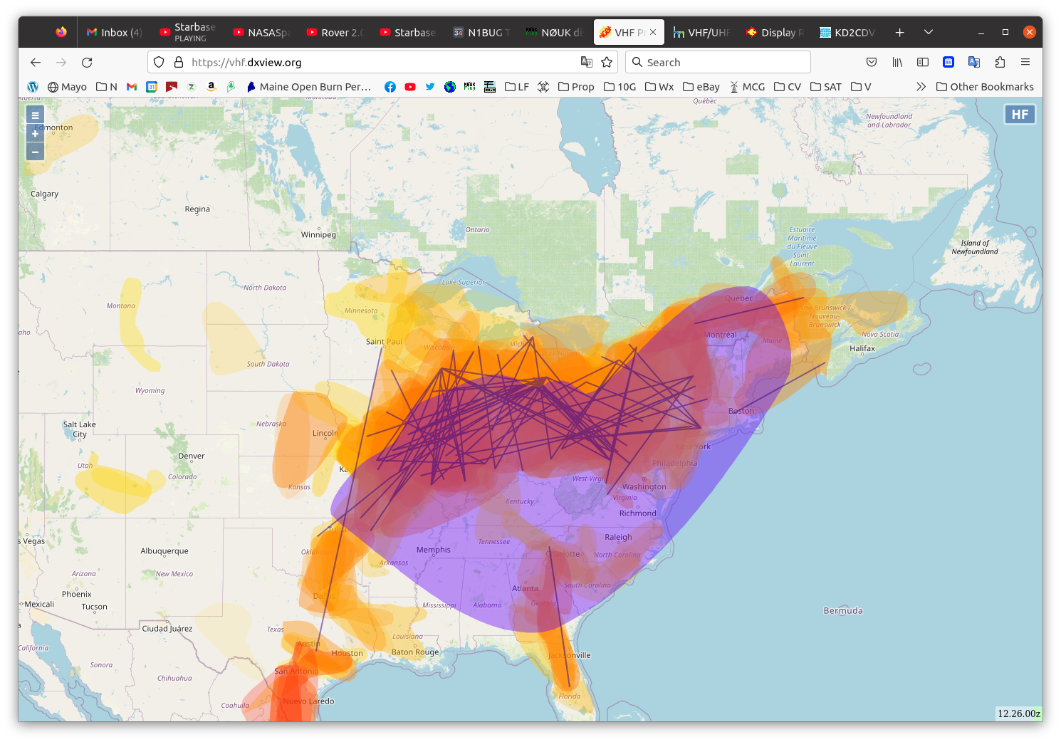
Around the peak of the VHF/UHF opening, the purple area was now over me. This was shortly after that incredible 432 QSO with N0PB.
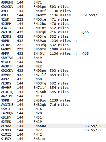
Other notables were AA9MY, 1088 miles on 222, W9FF 1136 miles on 432 (Q65), W9VHF 854 miles on 432 and 144, VA3IKE 716 miles on 144, and N0PB 1239 miles on 144. What an amazing event for a tropo-deprived Mainer. Here is the list of QSOs for the opening.
This was, as is usually the case, an all digital event except for the one QSO with W9FF. I spent some time calling CQ on 144 and 222 CW but had no takers. I did not hear anyone else on CW or SSB except for my VE9 friends at the end of the opening.
I have been trying to find ways to stay active in ham radio during challenging times. Lately I have been experimenting with simple homebrew 40 meter CW rigs. My fist try was a Pixie kit. The Pixie is a true minimalist transceiver with very few parts. I had one years ago and thought it worked pretty well, but this latest one I got didn’t seem so great. Perhaps the circuit has changed or I have! It suffered terrible BCI (broadcast interference) from strong stations in the medium wave band. This was mostly cured by adding a 40 meter band pass filter. I tried to add a VXO (variable crystal oscillator) to get some frequency agility as I had done with my old Pixie 20 years ago but after weeks of playing around I gave up. This one did not want to move more than a kilohertz or so (the old one had no problem going 7 kHz), and the receive-transmit frequency offset changed as the VXO was tuned through its limited range.
The kit built Pixie with band pass filter
I soon gave up on the kit built Pixie and tried making one from scratch. I had all the parts on hand so why not? I experimented with adding audio filter stages and learned quite a bit in the process, but the pure homebrew version also didn’t want to move very far with a VXO and had the same problem with receive-transmit offset. I soon abandoned it too.
Homebrew Pixie with audio filter stage
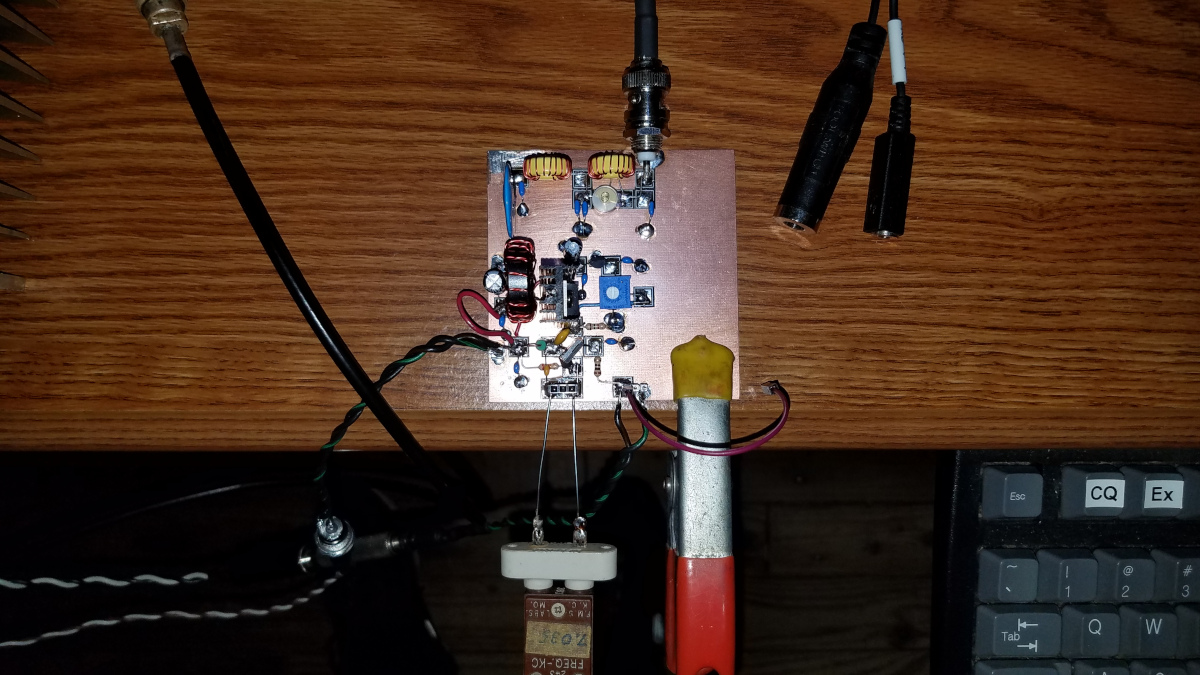
My friend Tom, KN4RRQ had built a two transistor transmittter following a design by VK3YE but was having problems getting good power out of it. It was supposed to do about five watts on 12 volts and 20 watts on 30 volts, but it wasn’t. It uses a BD139 transistor oscillator followed by a IRF510 or IRF530 amplifier. Tom sent me a few BD139s since I didn’t have any and I threw one together to see what I could get it to do. I had the same problem with very low output (about half a watt) until I added a bias circuit which brought it close to five watts. Harmonic levels were too high for my liking with the original low pass filter so I made the second stage of that filter a 20 meter trap which got that under control. Modifying the filter must have changed the load seen by the FET. Output was up to 8 watts operating on 12.5 volts! I put it on the air, using my FT-2000 to receive and my CQ was answered by Wolf, IN3TWX. I knew him from my 2 meter EME days so that was fun! Wolf gave me a 578 report with this little rig. It does have a bit of chirp.
The 8W20W transmitter as set up for the IN3TWX QSO
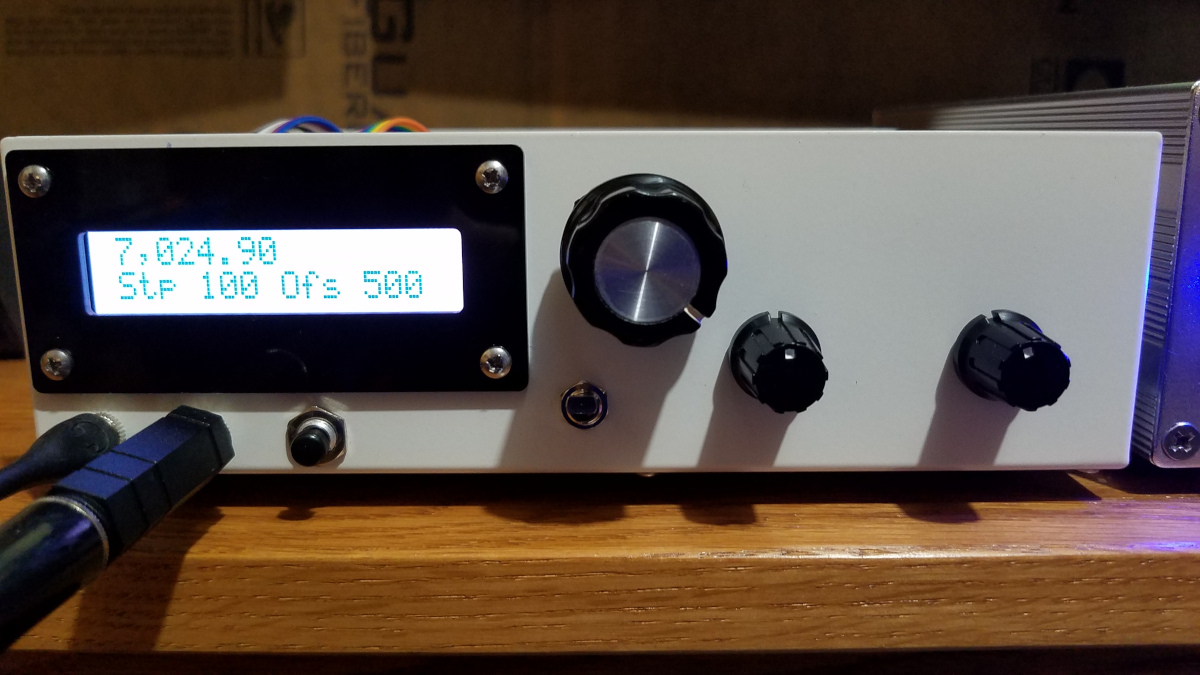
I was still looking for a QRP transceiver with frequency agility. I was able to save a few pennies and buy a DC40B transceiver kit and audio filter kit from Pacific Antenna. It put out a little over two watts when operated at 12.5 volts on a battery. I built a synthesized VFO using an Arduino nano and Si5351A synthesizer module. I started with a design by W3PM from QEX July/August 2015 and made a few minor changes. I added a low pass filter and post-amp to bring the level up enough to drive the DC40B. I had a few trials getting the VFO to properly drive the rig but eventually got it working well. Describing the rig in detail is not the focus of this post.
On the morning of July 29 I was calling CQ with the DC40BV (my nomenclature for the DC40B with VFO) on 7021.5 kHz when I heard the CY0S Sable Island DXpedition begin calling CQ on 7023 listening up (working split frequency). I was able to hear them because the filtering on this little rig is OK but surly not great. I wondered if I could manage to work them with this little rig? The receiver is direct conversion. I have it configured for a positive transmit offset since I normally prefer to listen on the low side of zero beat but of course being a D-C receiver it works equally well on the upper side of zero beat. If I tuned up to 7024 or so I would be able to hear CY0S and be transmitting one kilohertz or so above them, in about the right place for their split since they had just started up and there was no pileup. I hastily dialed up, actually going a bit higher than that but I could still hear them due to the somewhat wide audio filter. My first call went unanswered and they called CQ again, but my second call got them! I worked CY0S with a 2 watt kit/homebrew transceiver with direct conversion receiver! If there had been a pileup the QRM would have killed my ability to hear CY0S since I would be listening right in the middle of it, but I was in the right place at the right time when they had just started up and had very few callers. A 400 mile QSO is no great feat but it was fun working a semi-rare DXCC entity with such a simple and unlikely setup!
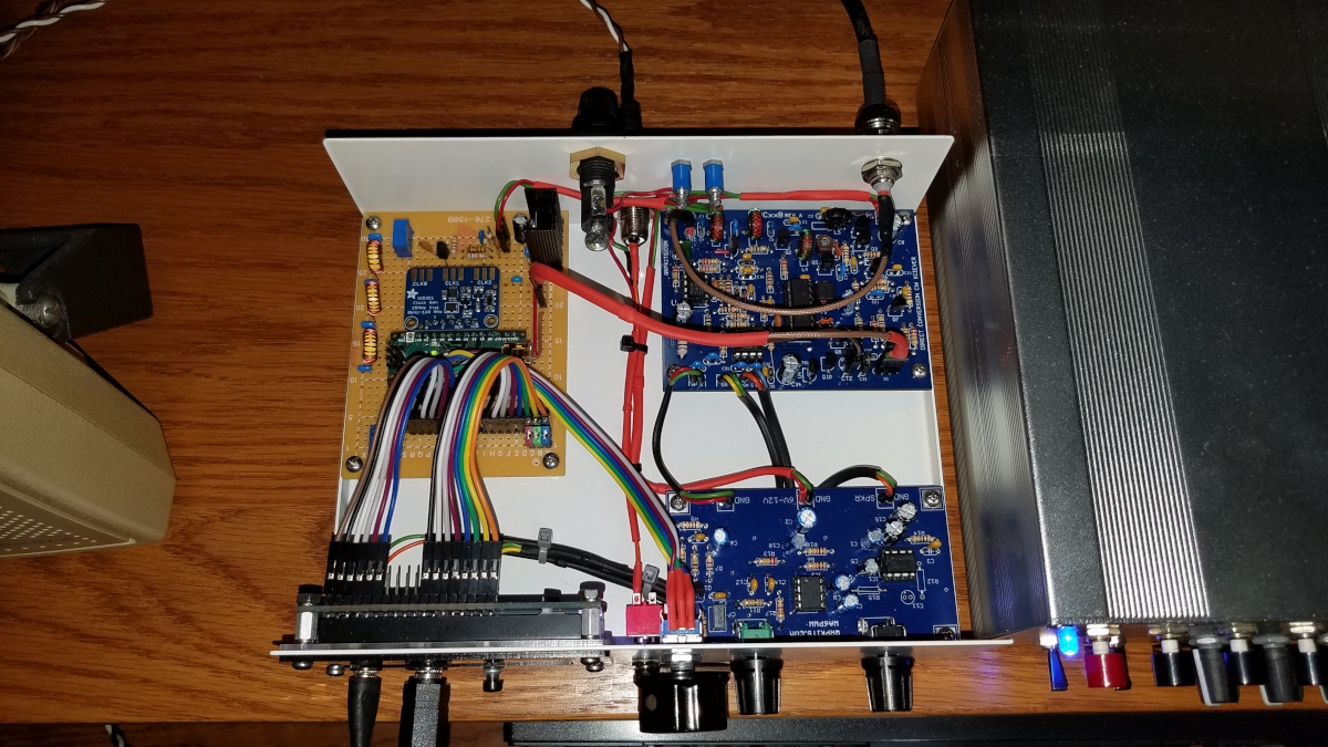
The DC40BV immediately after my CY0S QSOInside view of the DC40BV rig. I am still making a few minor changes and have some more tweaking of the VFO code and capabilities to do.
I was already thinking about having the ability to toggle the receive-transmit offset to plus or minus 500 Hz (my preferred pitch for listening to CW) because with a direct conversion receiver listening on the opposite side of zero beat can be helpful in avoiding QRM. But this QSO got me thinking. Perhaps I will try to make the offset completely variable, so I can go either side of zero beat and even have fully configurable split frequency capability. That will test my limited Arduino coding capabilities, but I think I can get it done with some trial and error.
I have a passion for radio, but it goes deeper than a hobby for me. As I continually struggle to maintain my relative independence amid the challenges of some very frustrating and debilitating challenges, it is a survival tool. To that end it is important enough to be among the highest priorities in life. Thus when misfortune struck I put much on the line to recover.
Over the past several years, with sacrifices on my part combined with generous contributions from fellow hams I have been on a station building spree. I got back into VHF/UHF weak signal work, greatly improved my HF antennas, and for some time was heavily into experimenting and attempting to work DX on 2200 meters. Things were going very well but all of that changed one winter night in December, 2020. We had a wet, sticky snowstorm that night. All of my wire and yagi antennas were heavily burdened with snow. At some point the strain was too much for the 2200m T antenna that was suspended between my two 100 foot Rohn 25 towers. It broke at one end and fell. The sudden reduction in side loads on the towers caused them to move slightly. With the burden of extreme weight of the snow, this caused significant, but fortunately not catastrophic damage. Some yagi elements were bent, traps damaged, coax cables damaged, masts bent just enough to bind, and one Rohn 25 top section was bent slightly, causing rotation to be extremely impaired on that one. All of the antennas from both towers were going to have to come down for repairs to themselves and the towers.
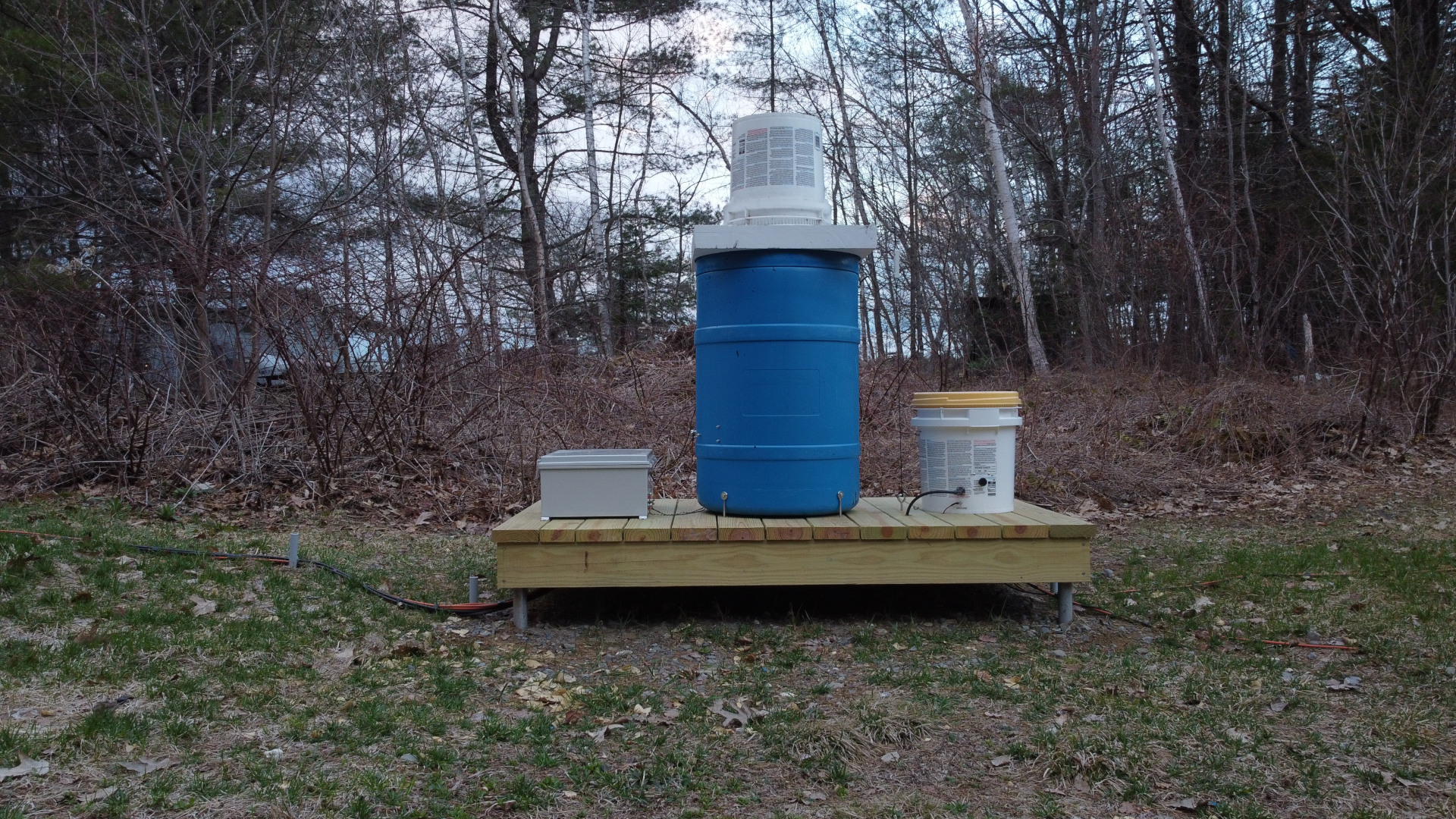
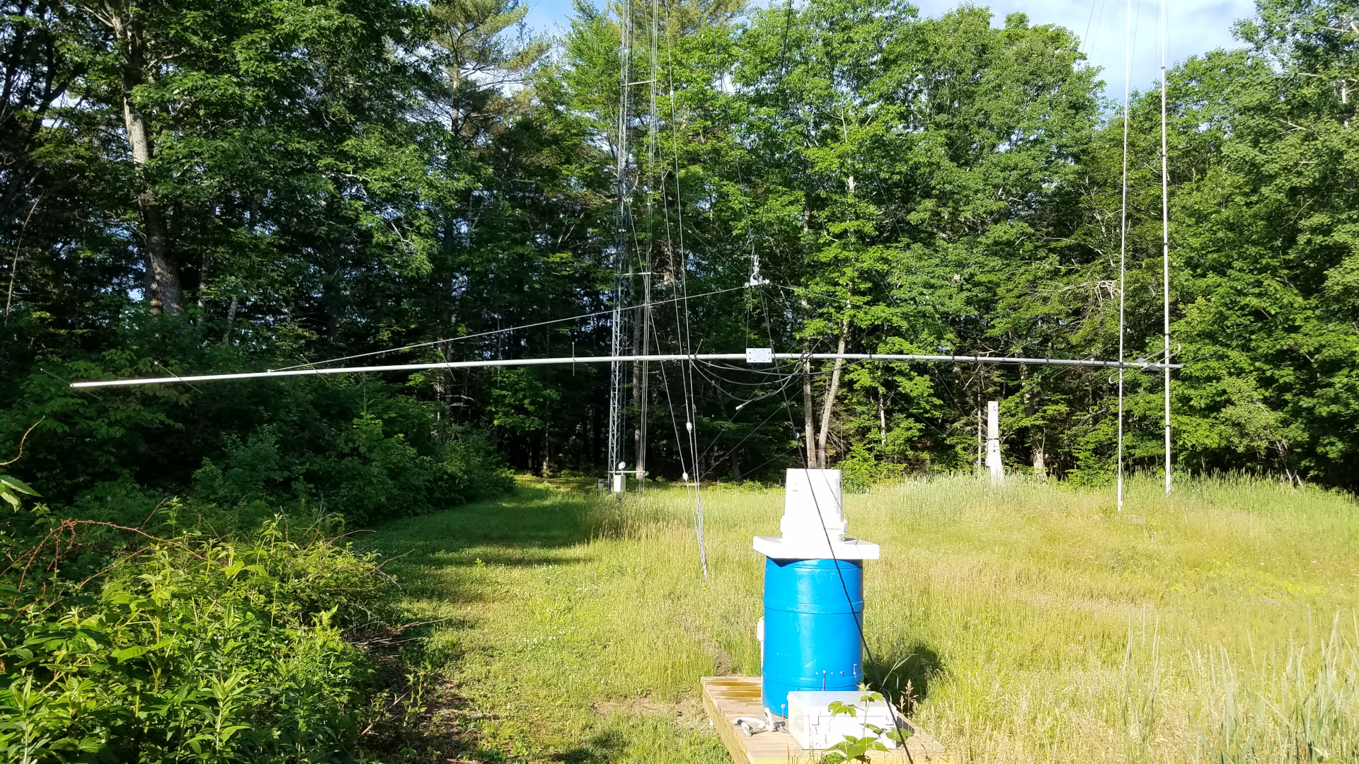
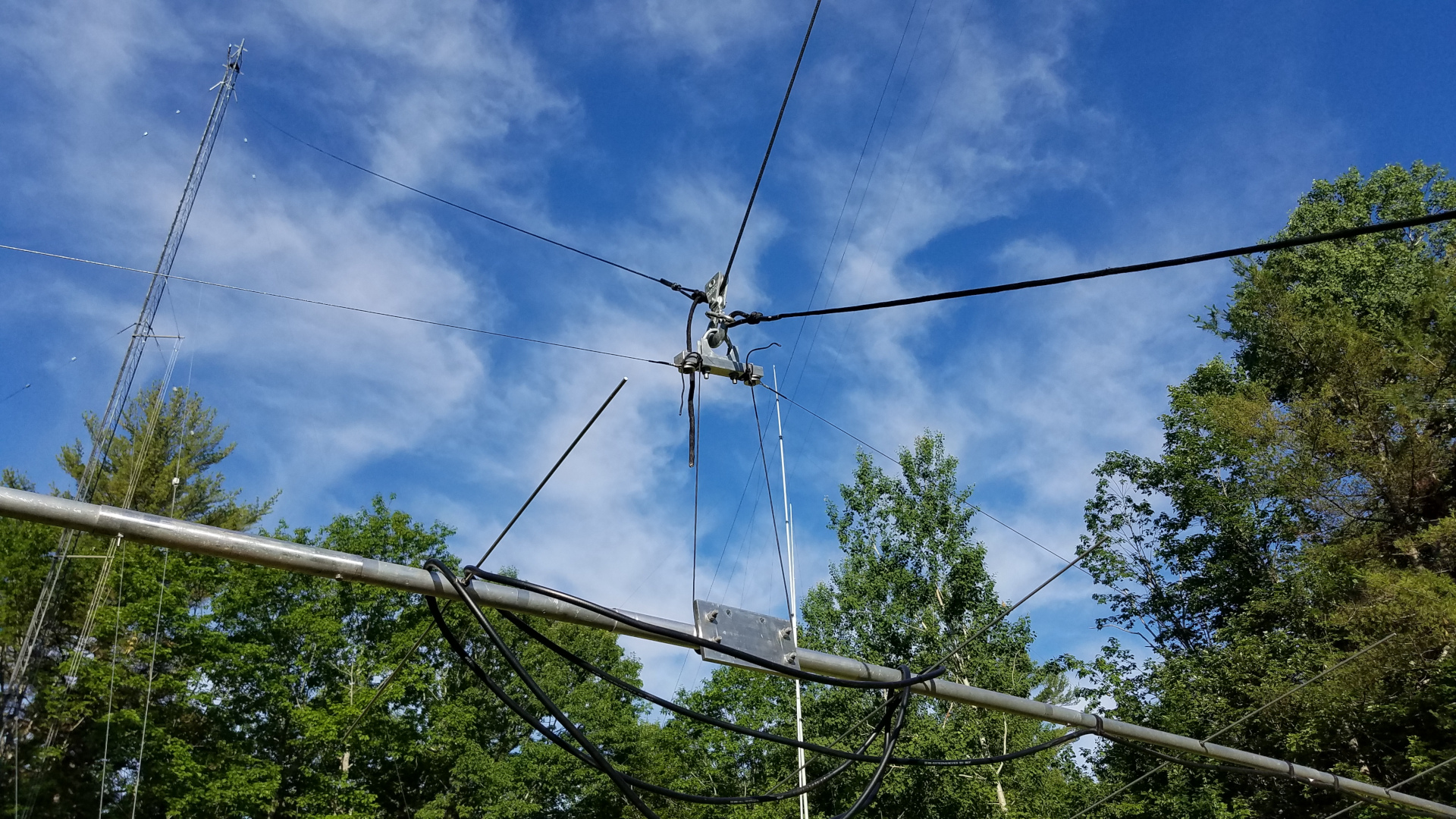
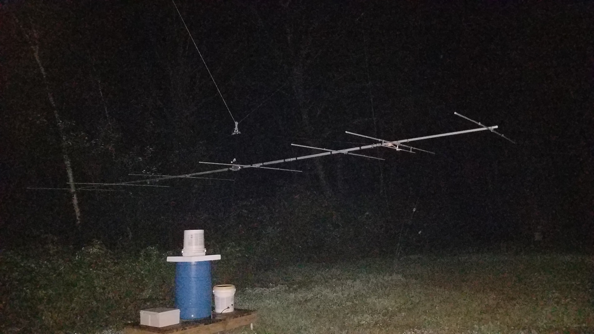
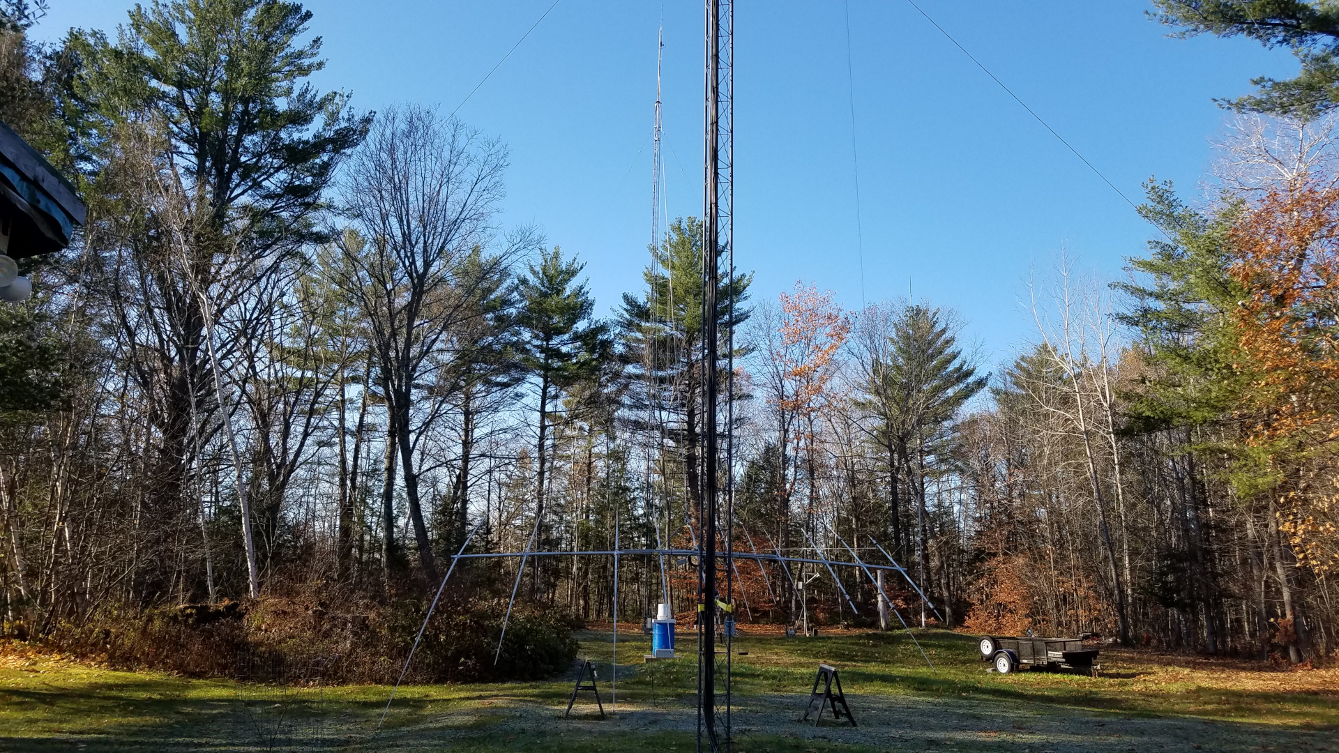
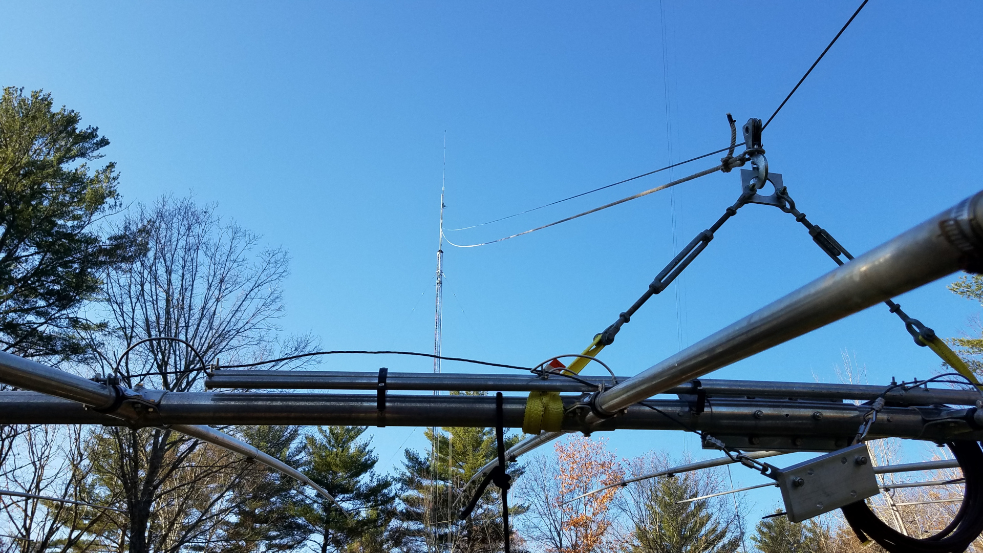
Side view of the 2200m antenna before the incident. It is strung from a point 103 feet up a tower on the right, and 95 feet up the tower on the left. That three wire top hat can accumulate a tremendous snow load under the right conditions.Another view of the 2200m top hat, taken from one of the towers. Failure occurred when the antenna broke free of an insulator at one end.Base and coil platform for the 2200m antenna. There is matching transformer and tap selection relays in the box at the left, a 2.2 millihenry coil/variometer in the blue drum, and a smaller version of same for occasional use on 630m in the bucket at the right.
There are no photos of the aftermath or 2200m antenna laying in the snow. I was too depressed that morning to want to document anything. I stabilized what I could and over the next several days foolishly repaired the 2200m antenna. That allowed me to continue LF operations until Spring but I knew those days were coming to an end. Assuming I was able to repair the towers and other antennas, I could never again risk a similar disaster.
The first challenge was how to finance repairs. If I chipped away at it with whatever I could manage to set aside from my income, recovery would take years. The other option was to see if I could get a loan, despite my fixed income falling below lender minimum guidelines. I was not doing so well since the loss of most radio activities. Under some gentle prompting from my health support team I decided to pursue a loan. Fate smiled upon me and I got the loan, a sum not less than a third of my annual income. It will take some time to pay that off but I was on my way to rebuilding!
It was going to be a big project for me. I do all antenna work alone. That means a lot of trips up and down the towers, as I have no one on the ground to do anything and must often make several trips up for simple tasks. There were complicating factors going into this. One was that several months earlier we lost a local ham and professional tower worker whom I had known for 40 years. He died in a fall from a tower. To be honest that really shook me up and I had some difficulty with climbing early on in this project because of it. I was at least 40 pounds overweight which compounds that darn gravity thing! But I was going to rebuild or perish in the attempt! Lastly there are always days that I am unable to work or be outside, and that has been greatly compounded by a neighborhood situation which has had several of us making complaints. It was very difficult this year to find times that I could do anything at all. I often started around 2:00 AM and finished work shortly after dawn. These same factors make it impossible to schedule work sessions even when volunteers might be available. Under current conditions I either do antenna work alone or it won’t happen at all. I don’t know how many years I will be able to continue this, so I am making the most of it while I can!
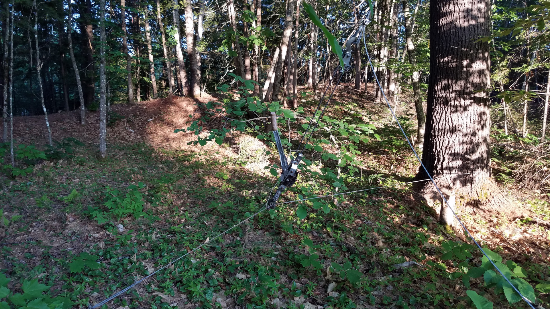
First there were preparations and getting antennas down from the more heavily damaged tower. The 2200m antenna was taken down for the final time, a very sad day since that extremely challenging band had been of great benefit to me. I miss it every day. Some trees that had rather quickly grown up along the path of my tram line were cut, and the tram line was hauled up into place.
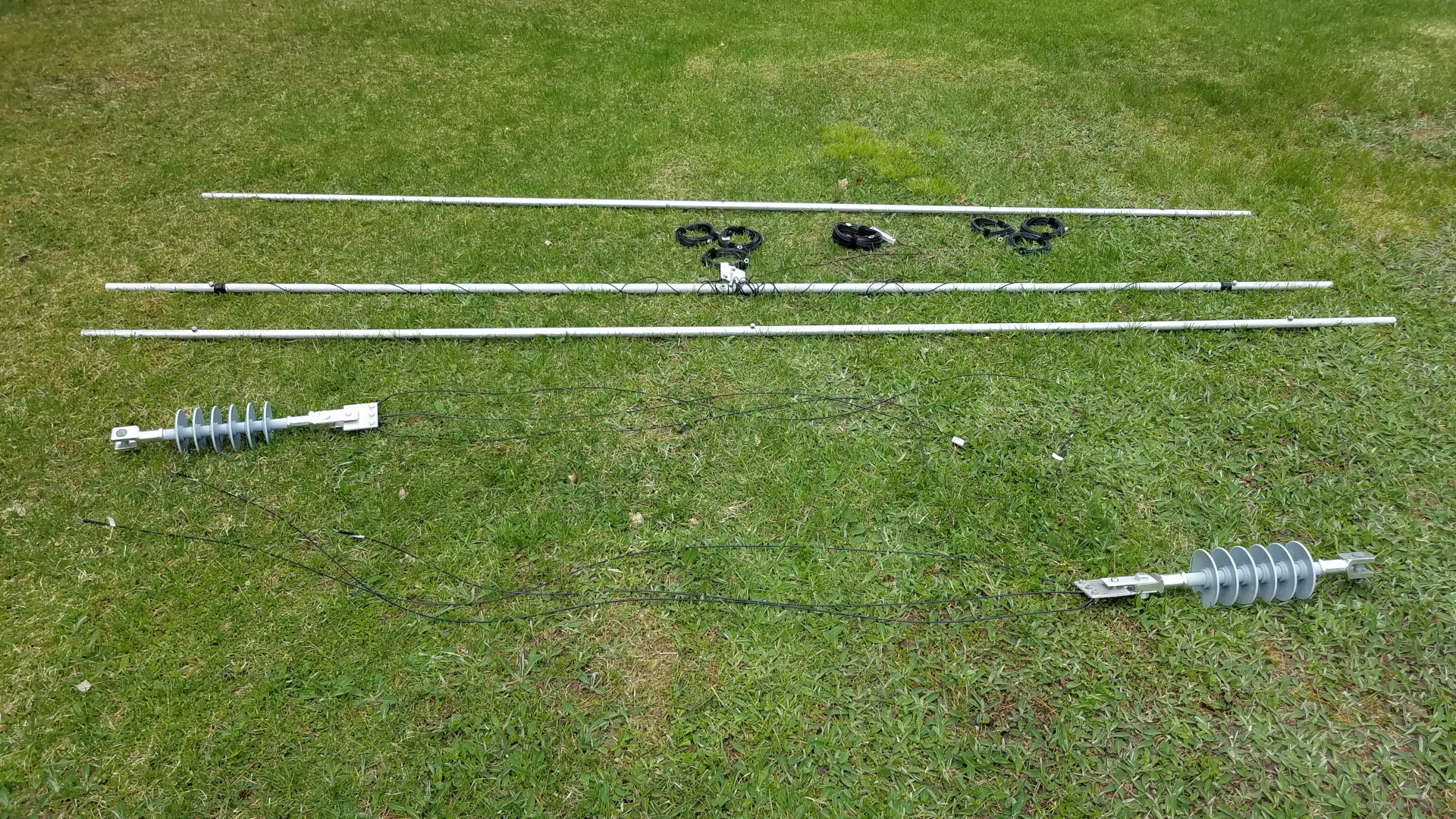
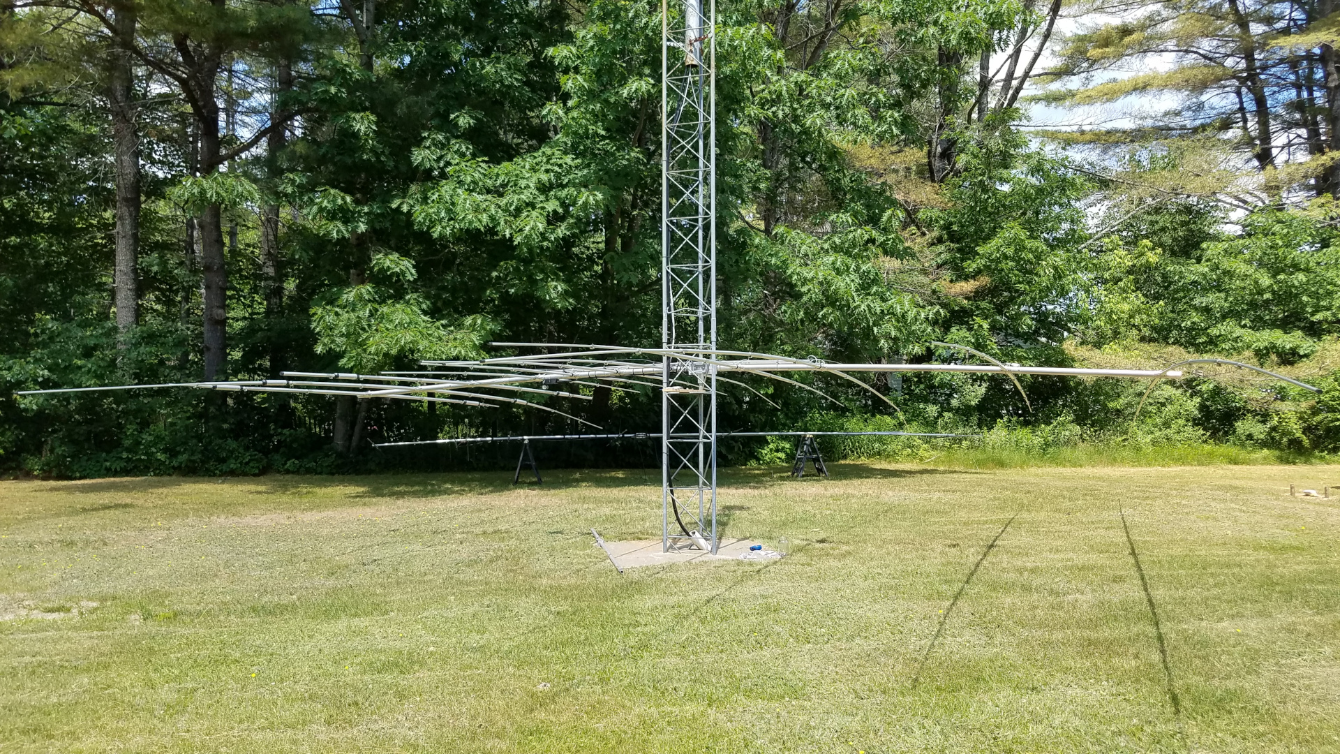
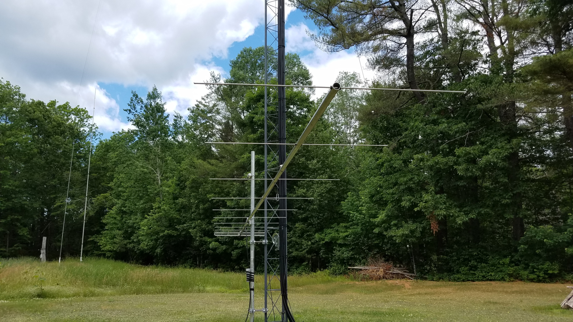
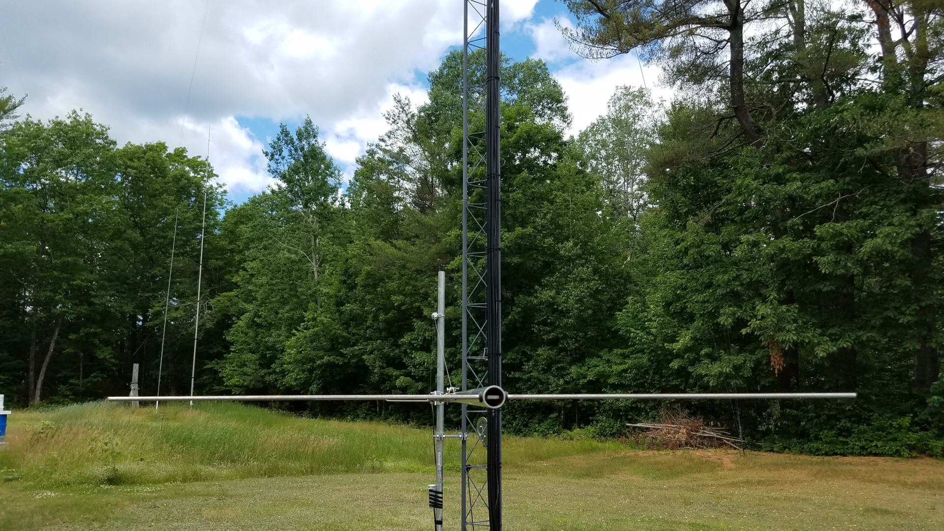
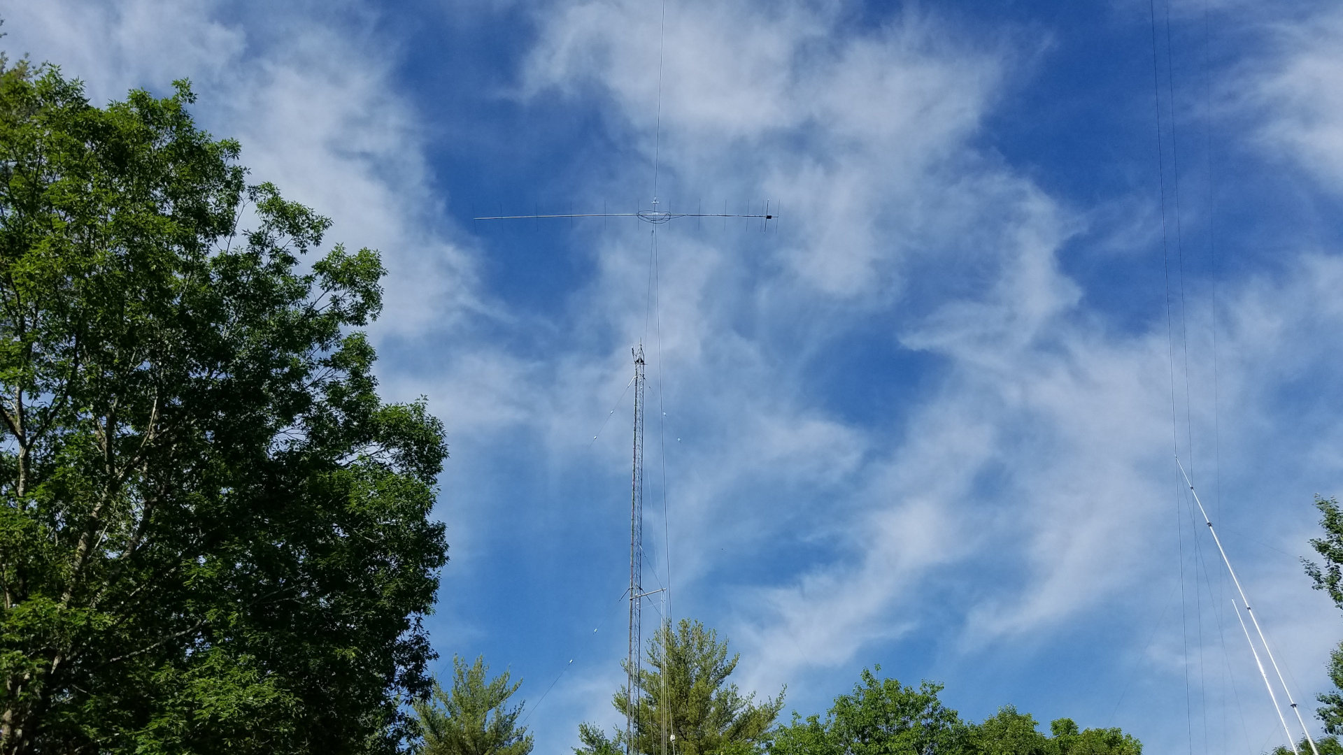
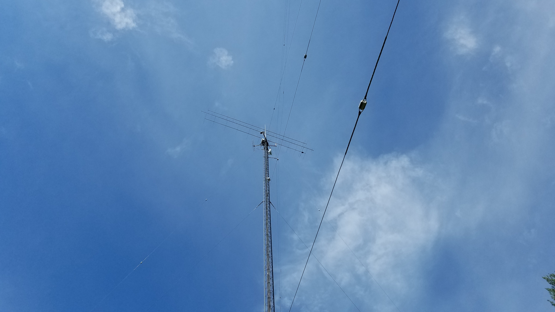
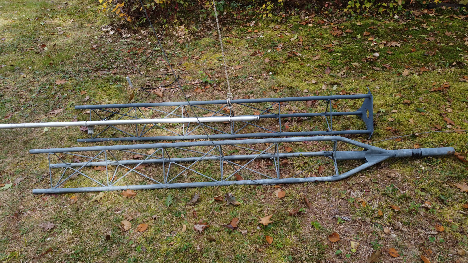
The 2200m antenna doesn’t look like much after disassembly! Some coils of wire, three 12 foot aluminum spreaders, and some big honking insulators.These antennas had to come down, even though things don’t look too bad in this photo. Traps on the TH11DX had broken (shattered!) plastic end caps and were weak and wobbly, some element tips were slightly bent and the boom truss was in danger of failing. Coax had issues on the 6 and 2 meter antennas, boom truss on 2m had partially failed, some 6 meter elements rotated out of plane, and the mast was severely binding in the tower top due to slight bending of both the mast and the tower top section.Trees have been removed from the area on the left to provide space for tramming.Ropes and cables for tramming operations. One wire rope is the tram line, the other is a backstay to prevent failure of the mast from the stress of tramming the heavy TH11DX.The mast backstay attached to a rope and ready to be pulled up.
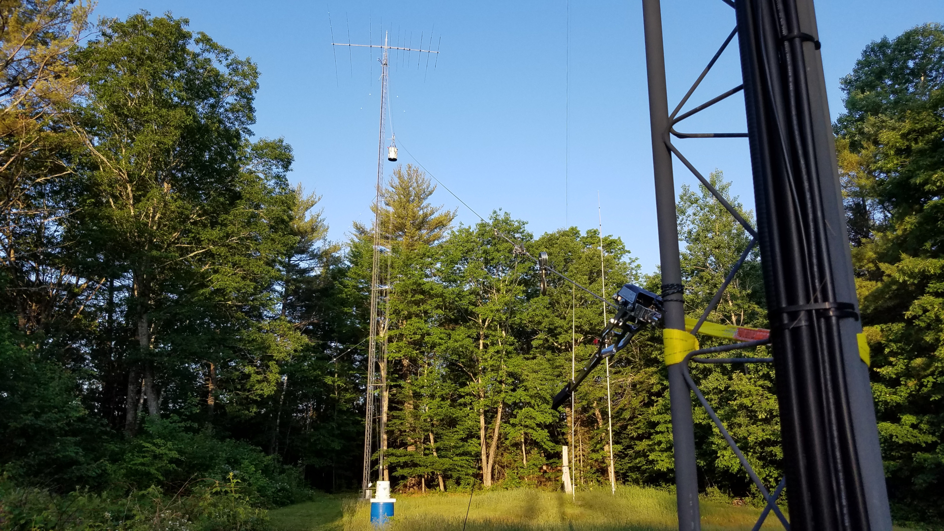
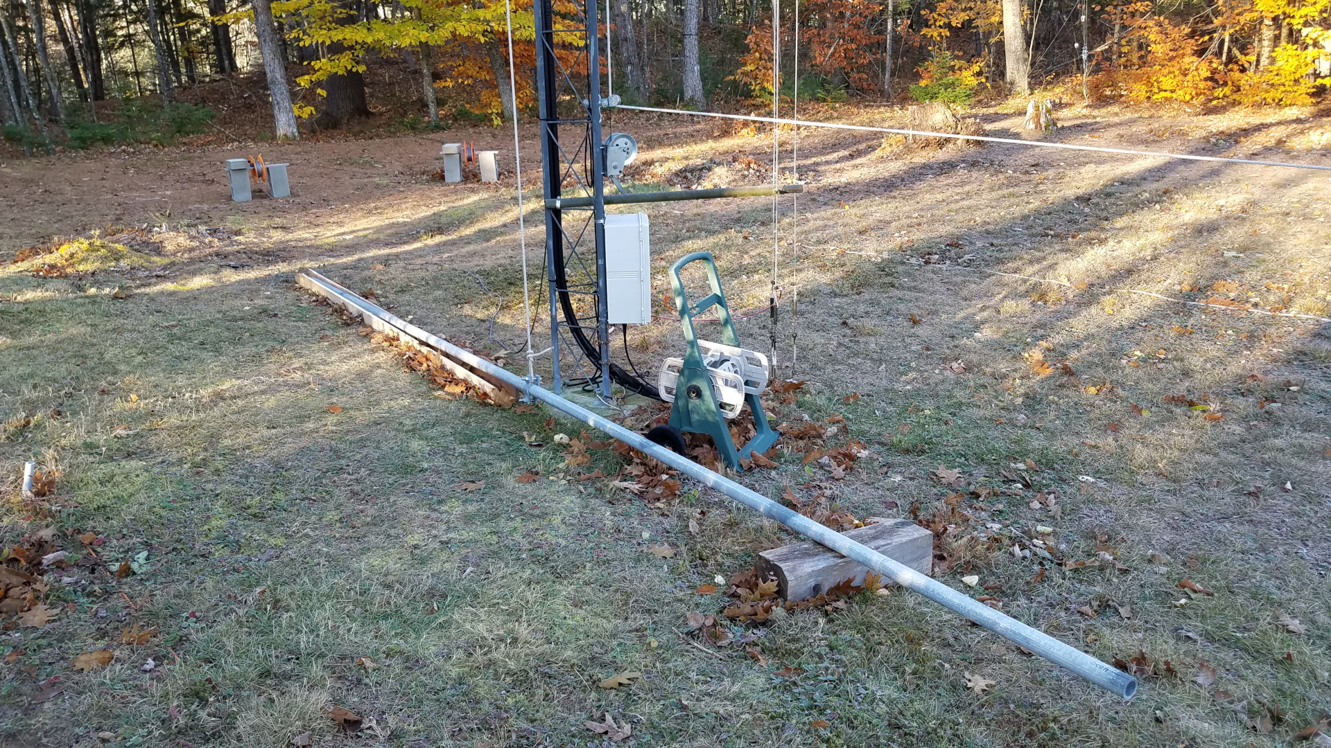
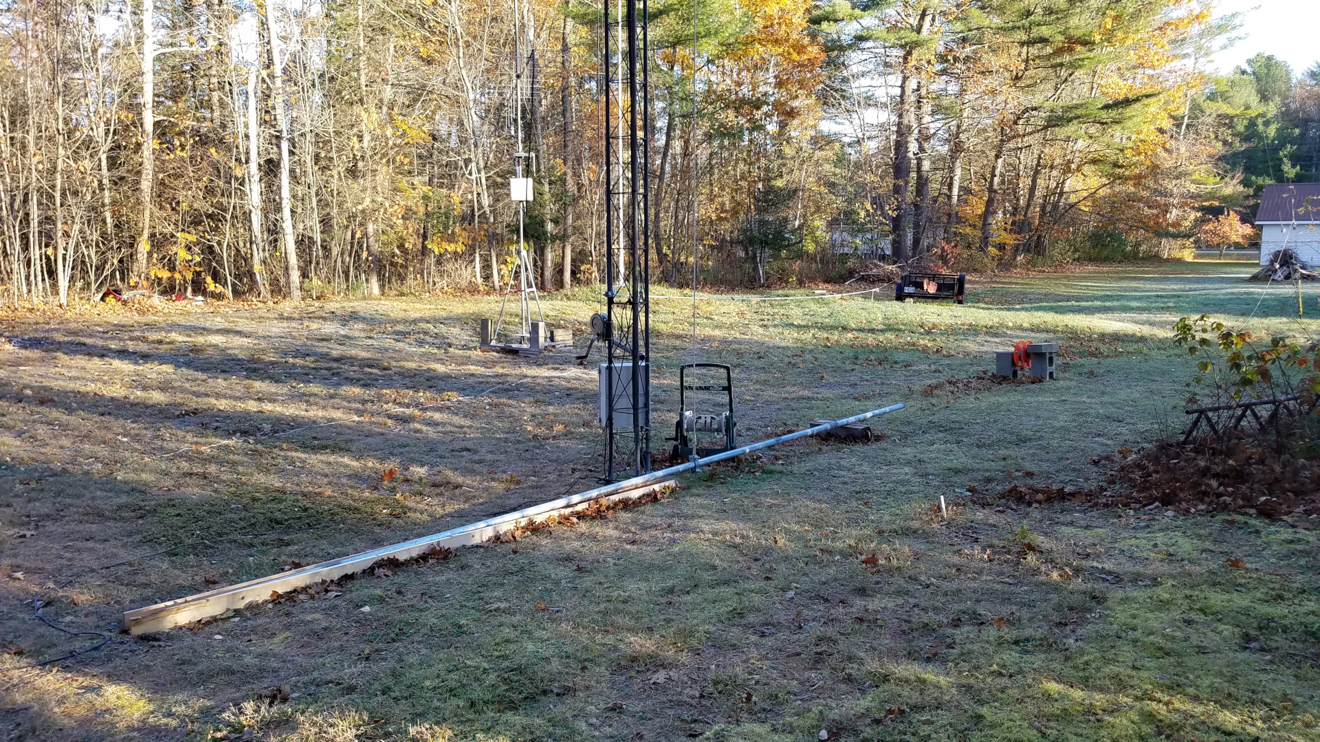
Special tramming operations needed to be carried out for the 6 and 2 meter antennas in order to get them past the elements of the TH11DX. It might have made more sense to remove the TH11DX first, but this was early in the season when I was very nervous climbing. To be honest, this was a mind game. I needed to see the big expanse of the TH11DX below my feet as I stood on a mast step to reach the upper antennas, or I would never get myself up there! I will argue that one should not climb if experiencing such discomfort and having to play such mind games but this was do or die for me. I was willing to take the risk of pushing myself into uncomfortable situations. In order to solve this clearance problem, the tram line was run horizontally from the mast over to the top of the other tower where it was joined to a rope running through a pulley down to a hand winch at the base of the tower. This allowed the VHF antennas to leave the tower going out horizontally, then to be lowered to the ground by letting out rope from the winch.
The 2 meter antenna suspended on the high, mainly horizontal tram line.Tram line being lowered with the 2m antenna hanging in the middle.The 2m antenna nearing ground level.6m antenna out on the high tram line.Tram line being lowered with the 6m antenna on it.Since I was still about 40 pounds overweight at this stage, I took advantage of the tram line to bring up my bucket of tools… less gravity pulling at me than if I climbed with it attached to my climbing harness.
With the smaller antennas down it was time to tackle the TH11DX. For this, the tram was rigged in a somewhat more conventional manner, now going from the top of the mast down to a few feet above ground on the other tower. After the nearly 100 pound antenna was at ground level, I learned that I need to eat more Wheaties or something! It was a struggle to pick it up, walk over to the short Rohn 45 tower with it, and mount it at shoulder level on that tower where it would remain until everything was ready for it to go back up.
The backstay tension system. This is critical when tramming nearly 100 pounds of antenna with a tram line attached to an aluminum mast!TH11DX suspended on the tram line. The tram line and backstay can be seen.TH11DX about half way down the tram line.TH11DX has nearly reached ground level.Tram line has been slacked off by means of the comealong by which the tram is attached to the slings on the tower. That lowered the TH11DX the final bit onto saw horses.The TH11DX moved to a temporary spot for repairs.
I was not doing so well after months of not having radio which I rely on for stress management, and really wanted to be active for sporadic E season and the Perseids meteor shower. I decided to repair and mechanically upgrade the 2m antenna and then temporarily put it on the other tower, below the 222 and 432 MHz antennas.
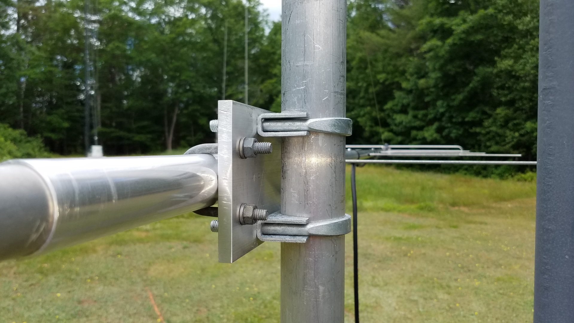
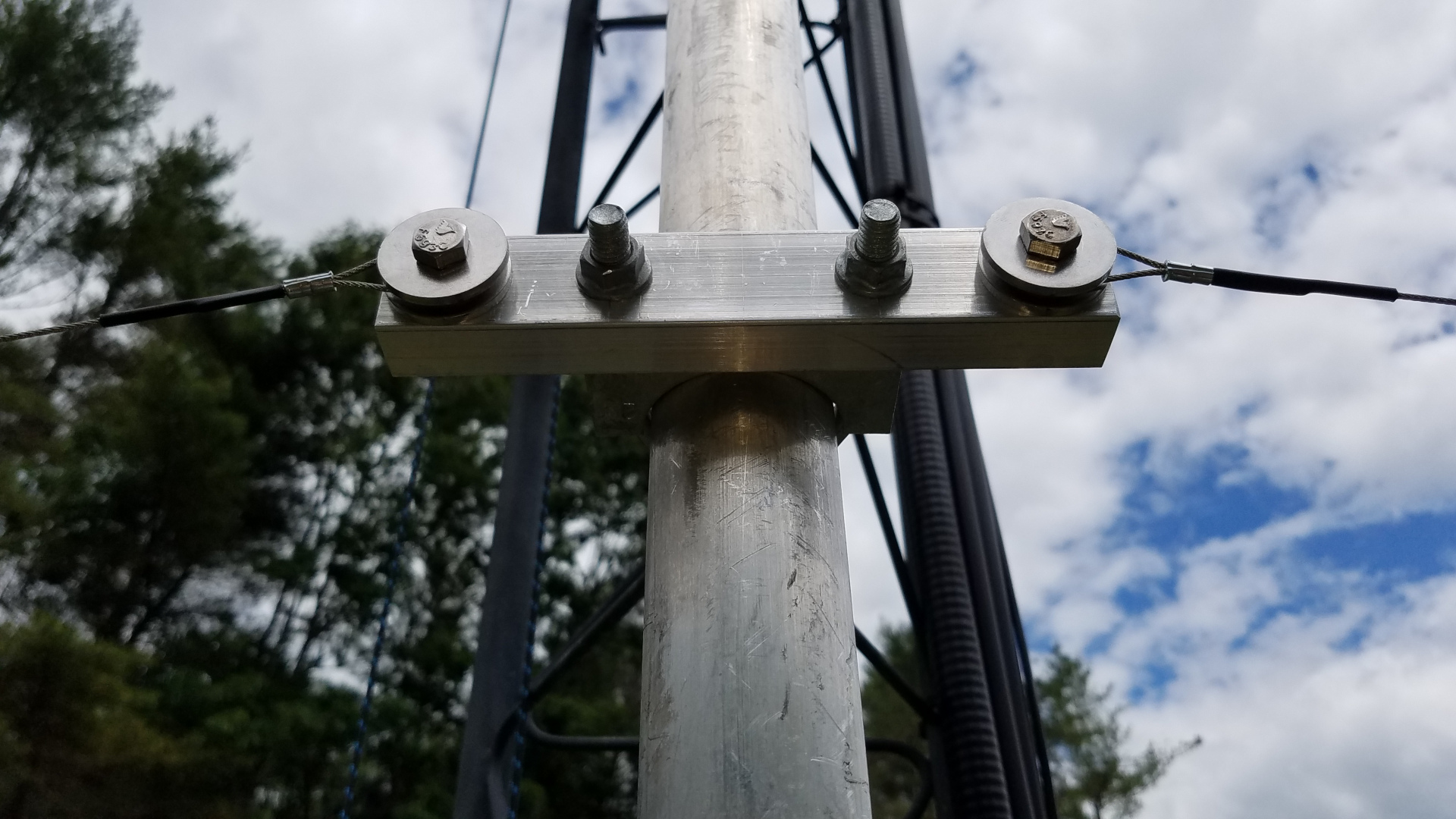
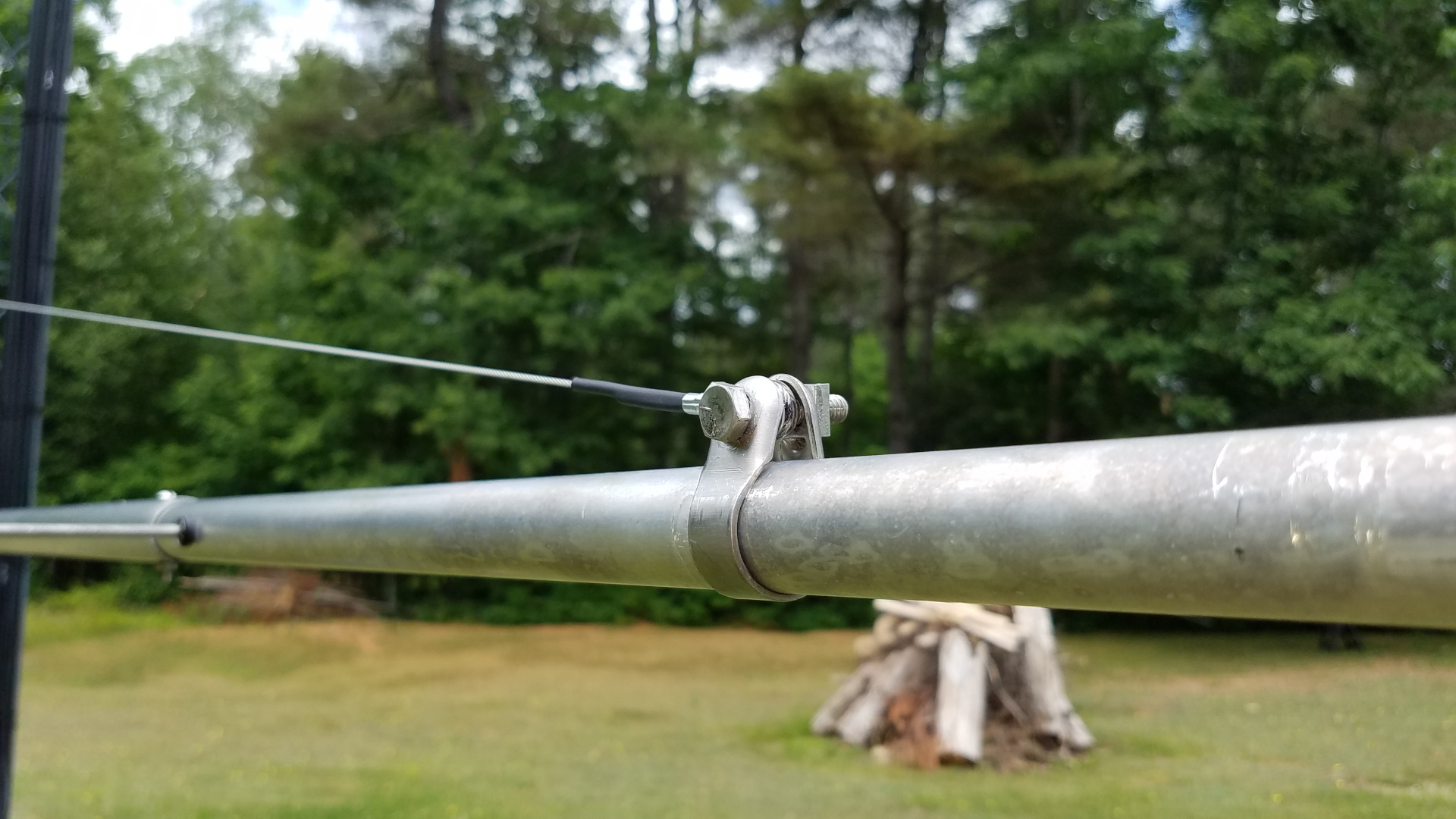
New, upgraded 2m boom to mast clamp. Overkill.New, upgraded 2m truss to mast clamp. Overkill, again.New 2m truss to boom clamp. The truss itself was upgraded from dacron rope (too stretchy!) to stainless wire rope.Refurbished and upgraded 2m antenna.OK, now I am happy with the alignment of elements!2m antenna on the tram line ready to go temporarily to the northeast tower. Rather than lower HF wires out of the way, I opted to use the same high tram running between the tops of the towers, but in the reverse direction (rope, pulley and winch now on the southwest tower).Quick and dirty rigging of antenna to tram line, but it works fine.2m antenna on the raised tram line.2m, 432 and 222 antennas on the northeast tower.
I caught a couple of massive E skip openings on 2 meters and did very well in the Perseids on both 2 meters and 222. I was glad I took this step of putting the 2 meter antenna up in a temporary fashion. After the Perseids it was time to remove all antennas from the northeast tower and get to work on the new VHF/UHF stack there.
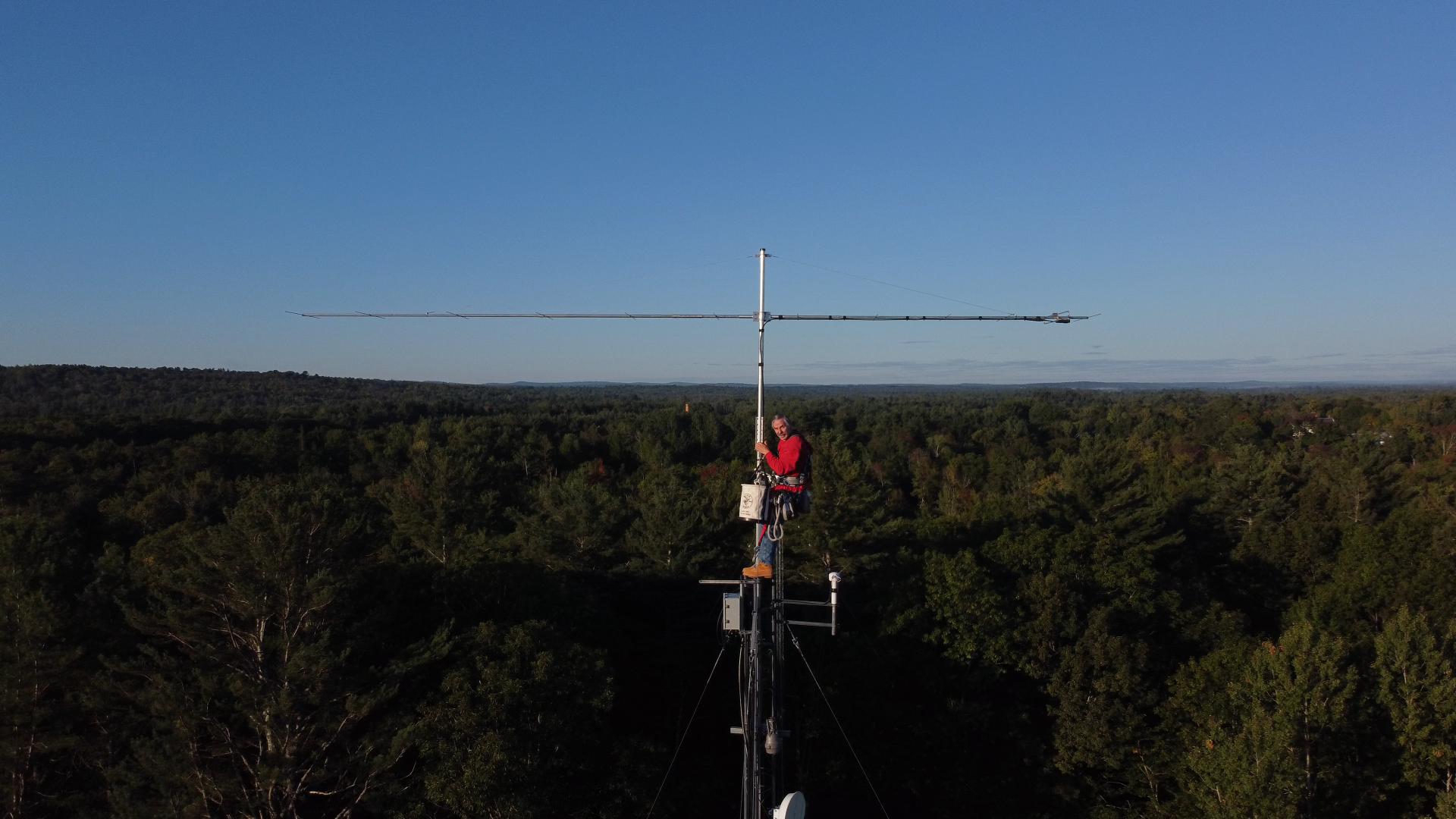
The 6m antenna needed two elements rotated back into plane, new boom to mast clamp, new truss to mast clamp, new coax and a rebuild of the center of the T match.All of the antennas down for work. 6 and 2 mounted on the utility trailer, 222 and 432 on saw horses, TH11DX on the short tower. 222 and 432 got new coax, new boom to mast, and new truss to mast.The 2m antenna hanging on the tram line before dawn, ready to go up at first light while there is no wind. It is going up already attached to a 6 foot mast extension.The 2m antenna is up. Photo clipped from a drone video.
I had a setback after getting 2m, 222 and 432 yagis up and mounted on the mast. While raising the mast to final position in preparation for rotator installation and adding the 6m antenna, the three coax cables got caught on the tower and damaged. I had to take all three antennas down and replace the coax a second time!
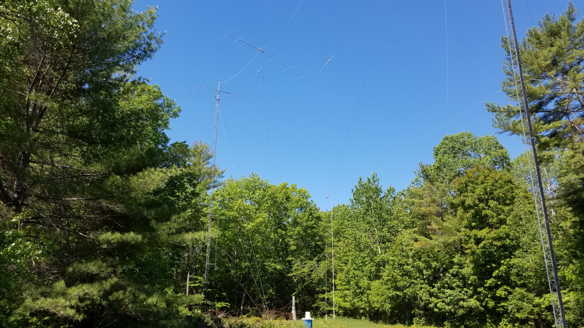
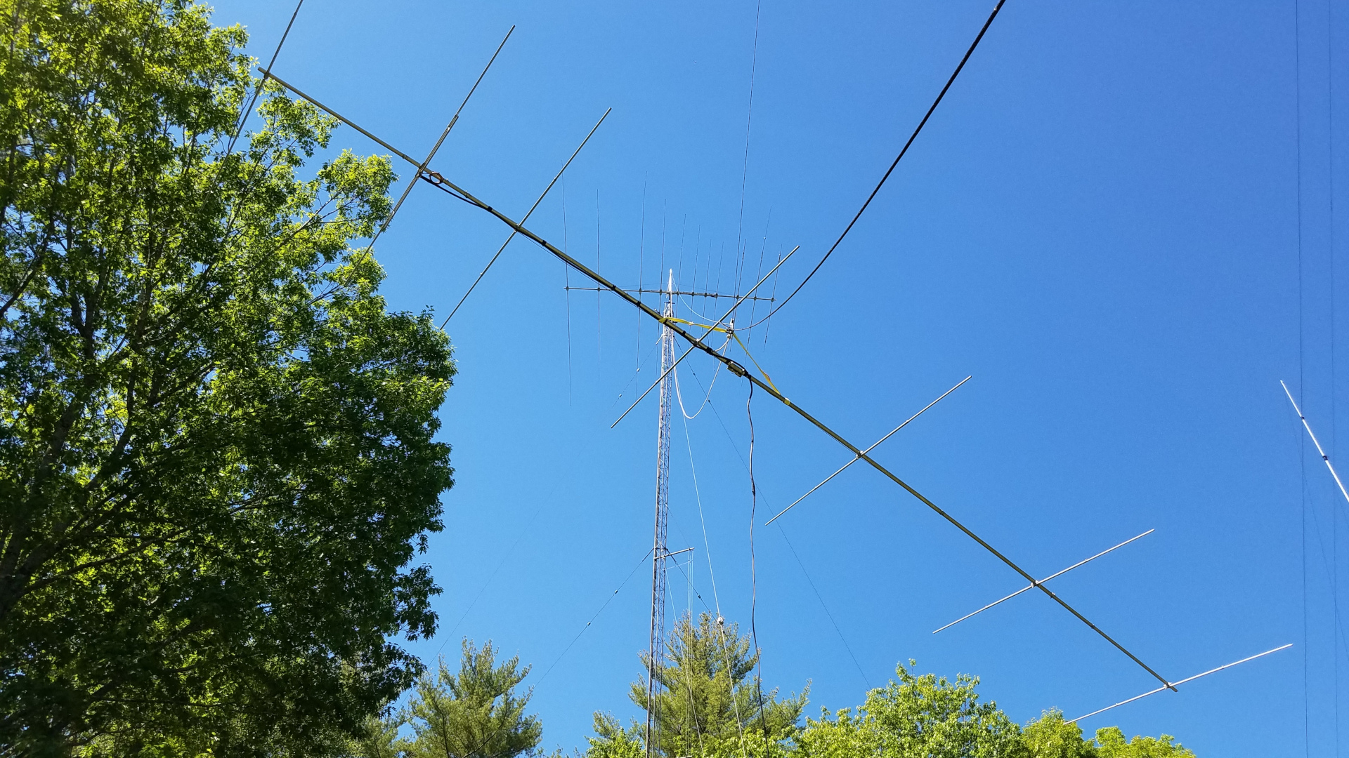
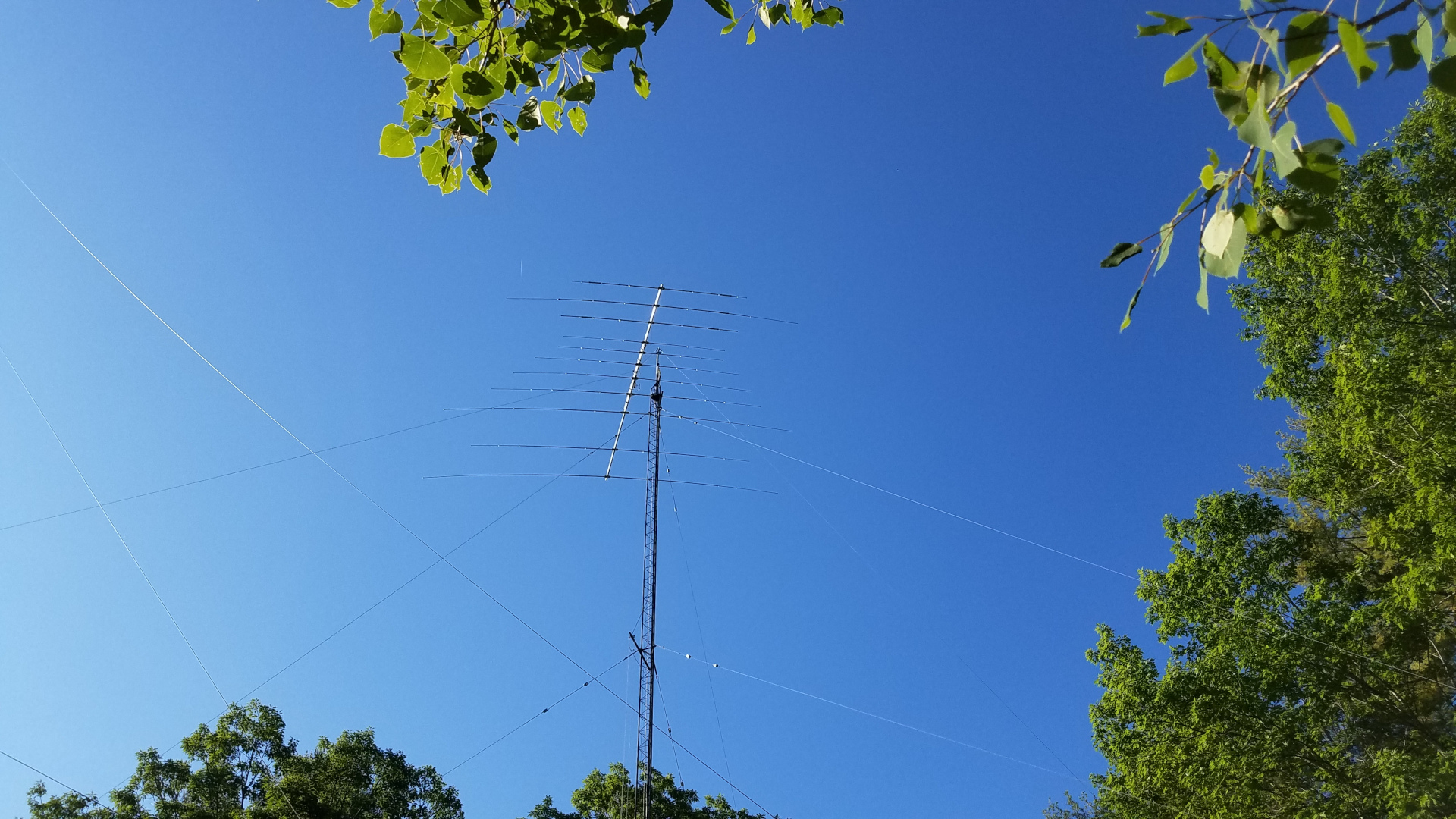
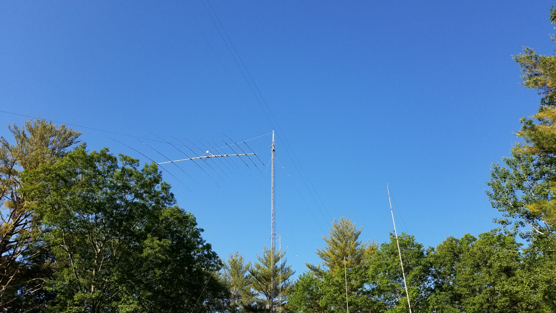
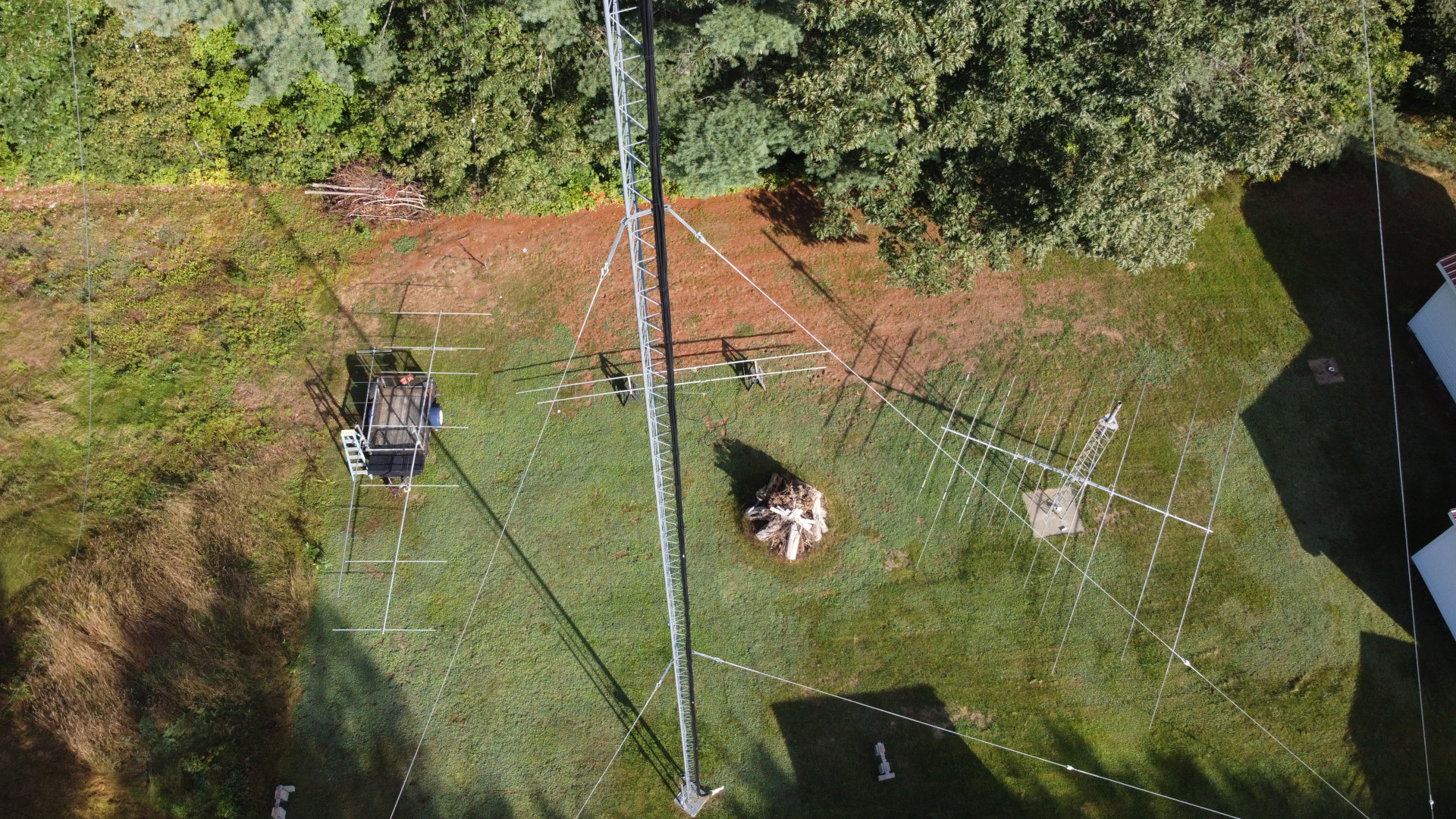
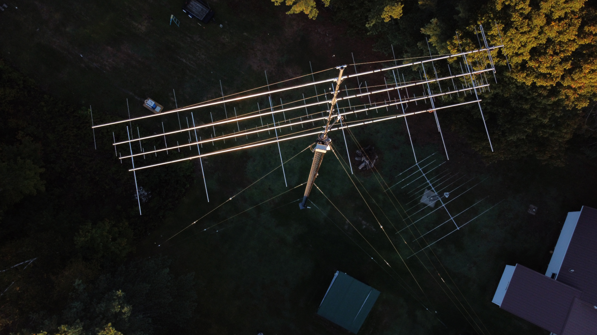
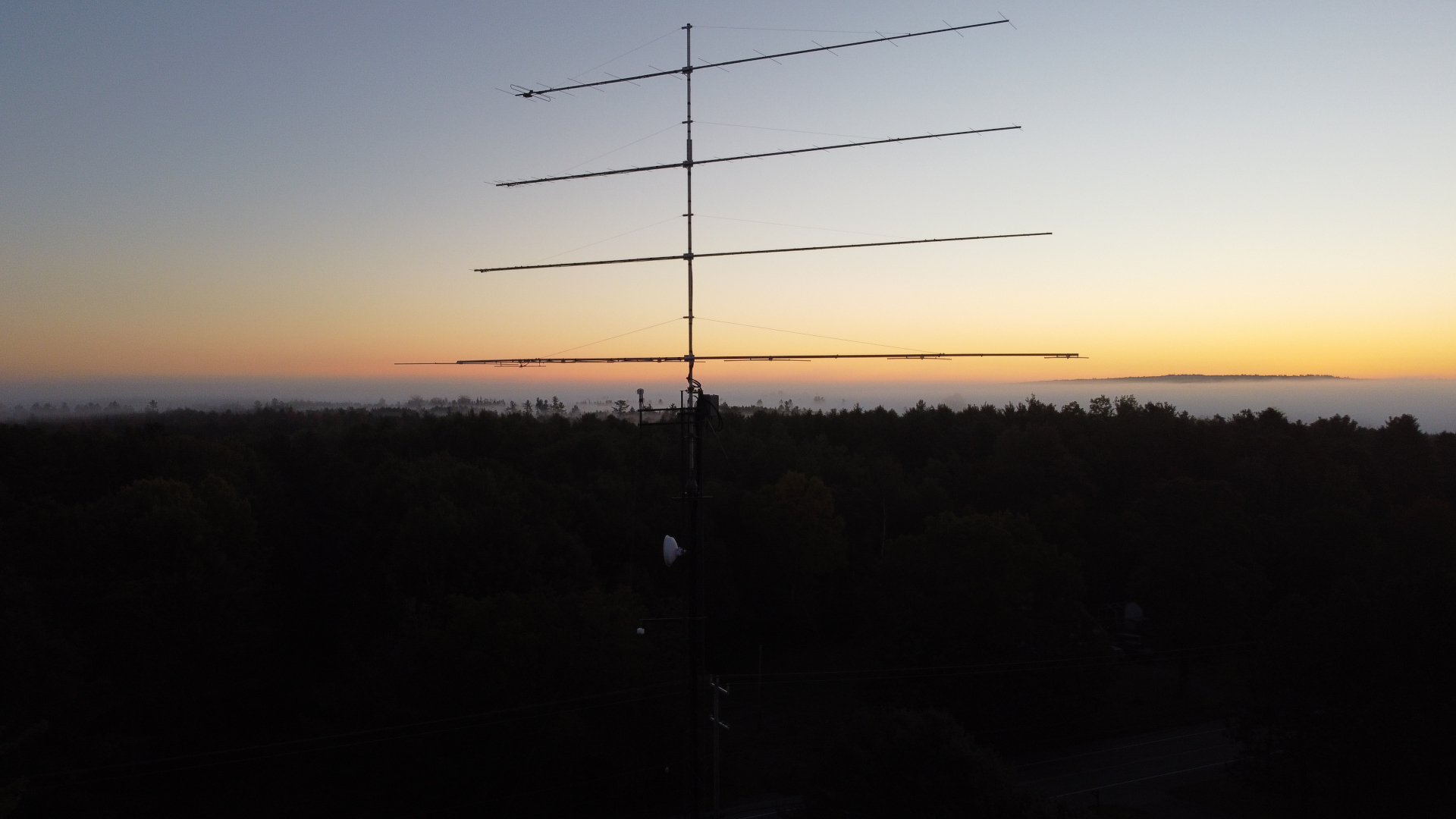
6m antenna waiting on the tram line for first light.Sun’s up! Time to go!VHF/UHF antennas up, northeast tower work finished (mostly).I am happy with alignment of booms on this stack.VHF/UHF stack from above.VHF/UHF stack just after sunset.
Now it was time to get to work on repairing the southwest tower. I added a temporary set of guys 10 feet down from the top and lowered the regular top set. The first challenge was removing the old mast and rotator. I had to hammer things apart and beat the mast out of the Rohn 25 pointy top section with a sledge hammer! That’s a lot of fun 100 feet in the air. Replacing the tower top section required some special rigging. I had LDF5-50A, 0.84″ CATV line and rotor cable all running up the inside of that tower! There was no way I was going to dig those buried cables up and pull them out of the tower if I didn’t have to. I couldn’t replace the top section using a standard 12 foot gin pole because it lacked sufficient height to lift a tower section straight up and free of the cables. I made a long gin pole out of a 20 foot section of 2 inch 6061 schedule 80 aluminum pipe and mounted it across two tower legs with pieces of 2 inch by 2 inch by 1/4 inch thick galvanized steel angle. As with all tower section lifts, I used a counterweight on the rope below the gin pole to take most of the weight of the section. I attached a length of 1.5 inch OD 1/8″ wall aluminum tube to the braces of the tower top section to act as a lever/handle so I could push it up and off the cables. This worked out pretty well, and the new stop section was rigged the same way for going up and over the cables. In the interim since the tower was first installed I had managed to acquire a 25AG4 flat top section which is far more desirable than the pointy top. After getting the top section replaced, the permanent guys were put back in place and the temporary set removed.
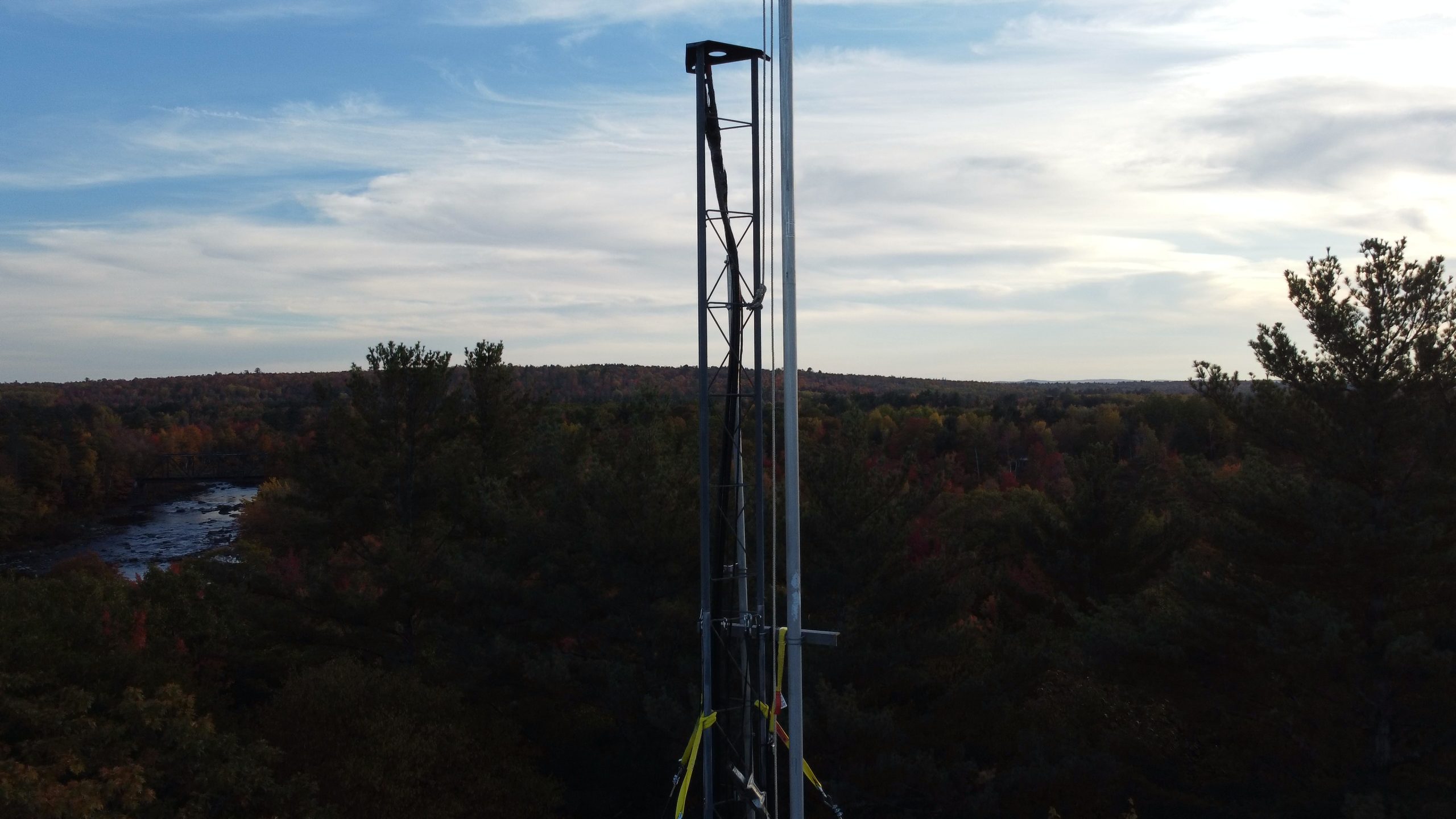
The old top section rigged for removal.The tower without a top section. Well, that looks a bit odd!Old top section and the new one rigged for raising.New top section in place.
I mounted a proper thrust bearing on the tower top, and put an accessory shelf at the bottom of the 25AG4 for the rotator. In between another accessory shelf was fitted with a centering bearing made of Acetal plastic. I used DX Engineering shelves and I must say they are far better than Rohn shelves! The top bearing is also a DX Engineering product. The next task was getting the new 22 foot long 4130 chromoly mast into place. Weighing 125 pounds it was going to be a challenge for me. I once again used the long gin pole to good advantage. Instead of using counterweights, I rigged a worm gear winch to haul the thing up. This was the one thing I did have help with for about 10 minutes. I hauled the mast up until the top of it was inches below the top of the tower, then had a helper run the winch while I was on the tower for the last 23 feet of lift and dropping the mast into the tower.
The mast ready to be raised.A different view of the mast raising setup.Tower top rigging for mast raising. From this angle, it doesn’t look like a 20 foot gin pole.The winch used for mast raising.Winch mounting. Well, it did work…The mast is in!The gin pole has been removed.
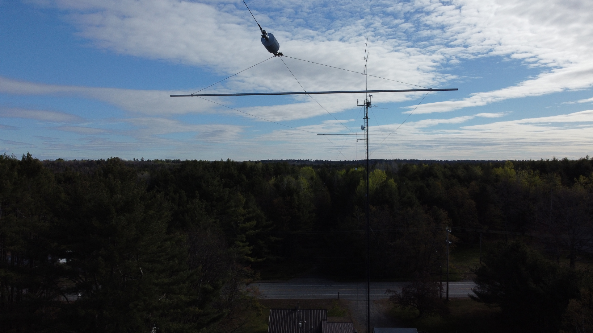
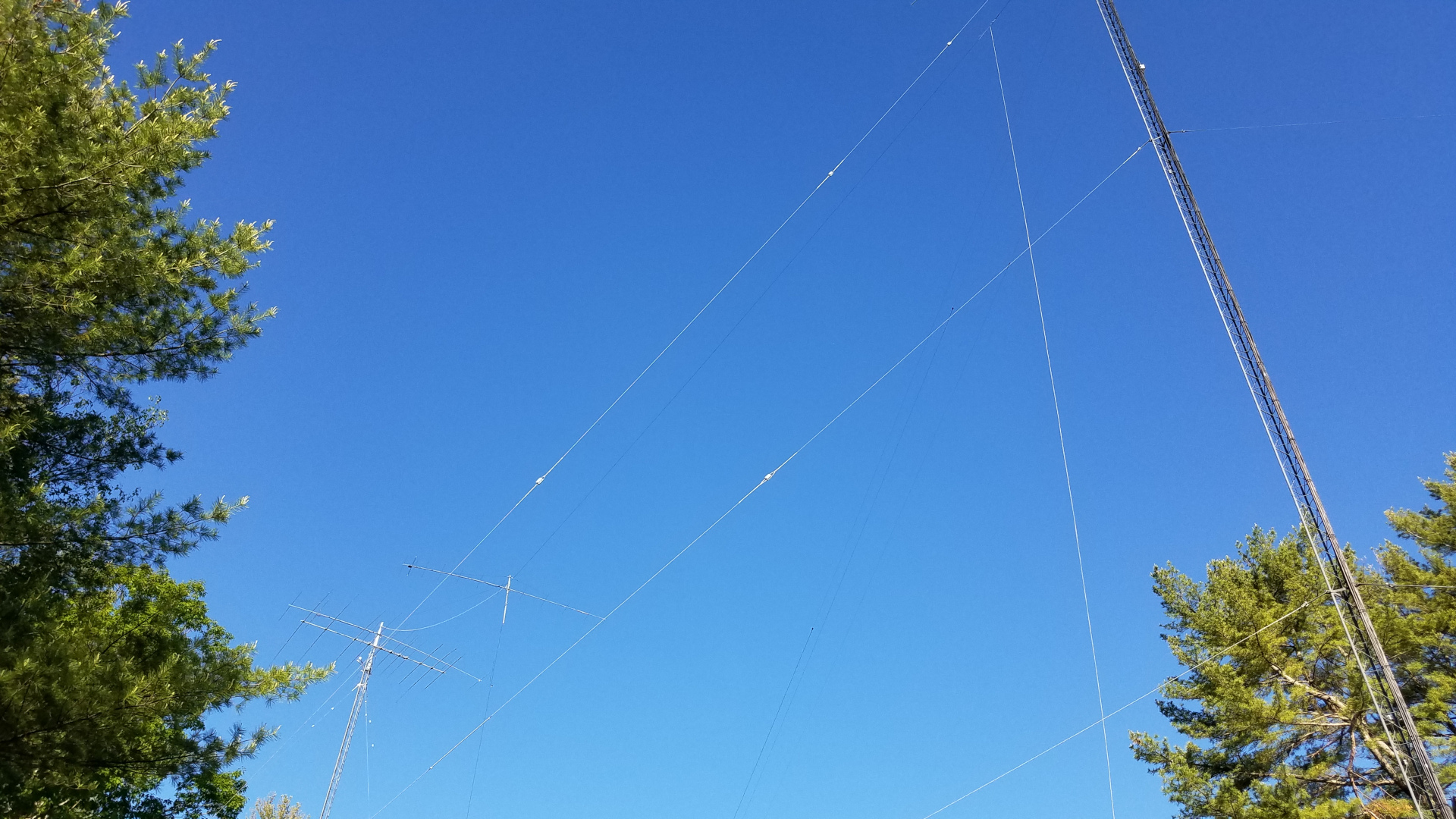
I did manage to sneak an upgrade into the rebuilding effort. I acquired an OptiBeam OB1-4030 rotatable dipole to replace my 40 and 30 meter inverted V antennas that always seemed to have me struggling to work the DX, let alone struggling for contest QSOs. I had been hearing that a dipole beats an inverted V at the same height, so I decided to try this after two failed attempts at home brewing a two band rotatable dipole in recent years. Besides, I was on a campaign to eliminate as many wire antennas hanging off the towers as possible. Skipping ahead, it turns out the improvement is nothing short of incredible! My 40 meter inverted V was at 104 feet, 30m at about 90 feet. The OB1-4030 is at 108 feet on the other tower 145 feet away. I was able to leave the old antennas in place for a while to make comparisons. The OptiBeam beat the inverted V antennas by margins ranging from 5 dB to more than 35 dB depending on the station and time of day! Every time! I have done extensive comparison using the Reverse Beacon Network. I have also experimented with calling DX stations many times with the old antenna and then the new one. Often they continue to CQ while I call time and again with the old antenna but I work them on the first or second call with the new one. I can work DX I never could before and get a much better run going in a contest. This is just amazing! Most of the time I found I no longer needed Beverages for receiving on 40 meters. The exception being during multipath conditions where the CW was difficult to copy. Then the Beverages still provide advantage.
The TH11DX needed more attention than any other antenna. The traps were taken apart, modified with additional screws to reduce wobble, shattered trap caps were replaced and covered with 3 layers of Super 88 vinyl tape, element tips were straightened, coax replaced and the ridiculously inadequate boom truss hardware was replaced with something more reasonable.
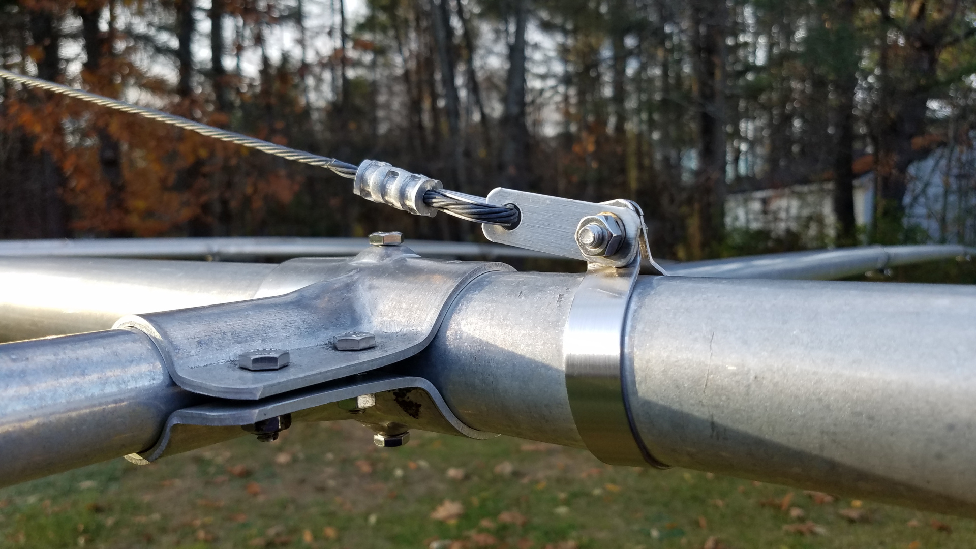
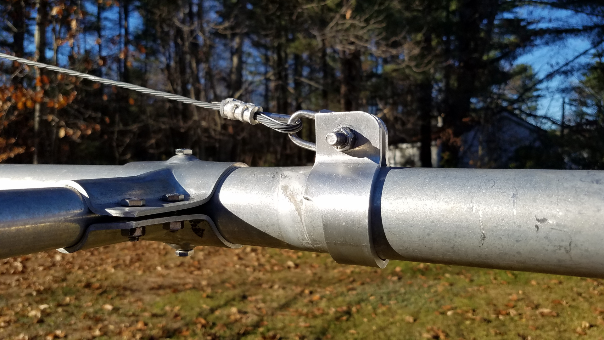
Original TH11DX truss to boom clamp. Seriously, MFJ/HyGain?Truss to boom clamp replaced with a DX Engineering part.The original TH11DX truss to mast clamp, which had broken after only one year of service and had to be patched up on the tower. It was nearly ready to break again. Ridiculous.The new home made truss to mast clamp.
Six years ago I struggled to tram the TH11DX up working alone. I did it by hand, wrapping the pull rope around my waist, leaning back and walking backward for the pull. I was pleased to see that now, at the age of 58 I can still do it, and somewhat easier than the first time. That’s odd but I’m not complaining!
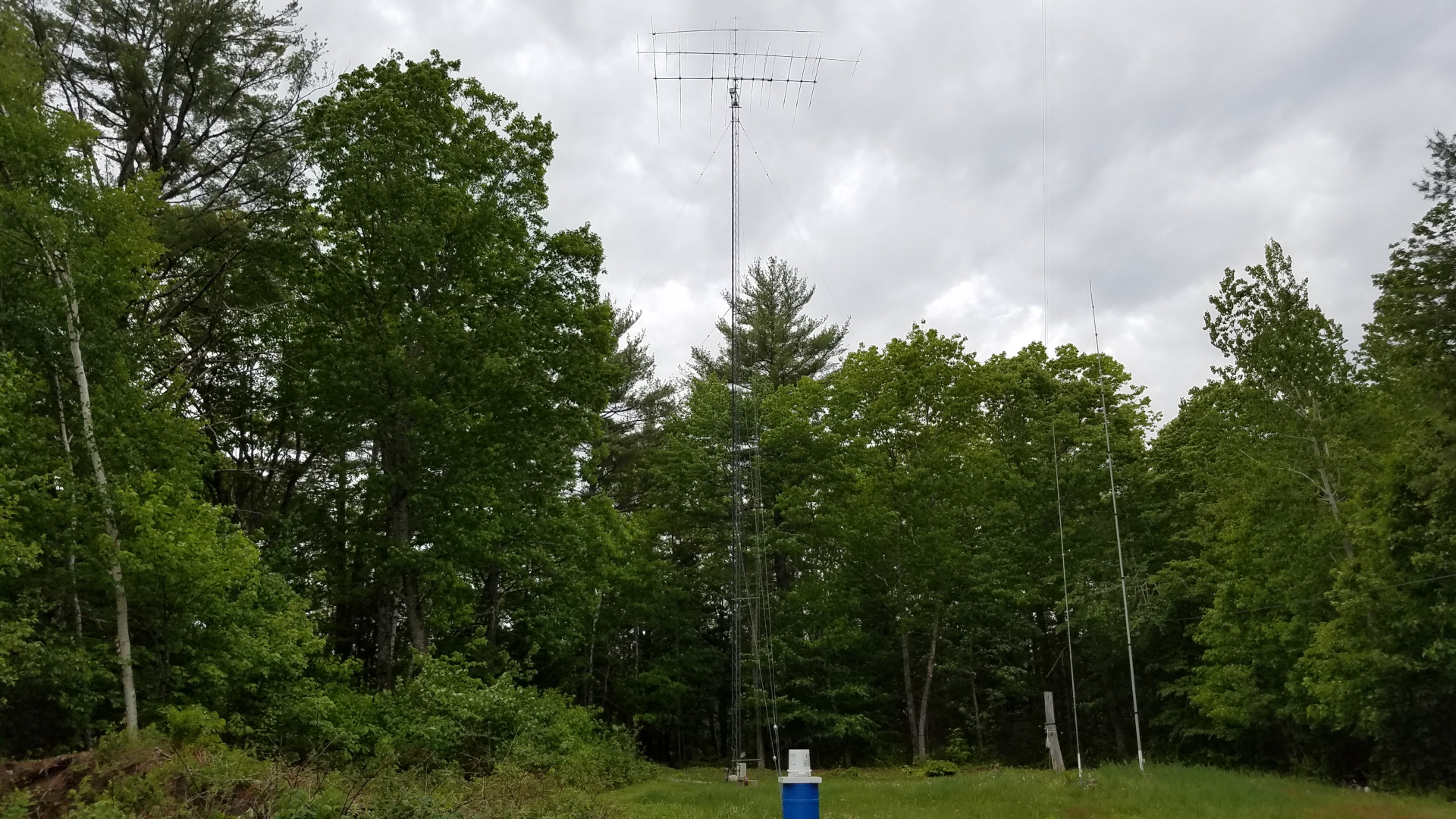
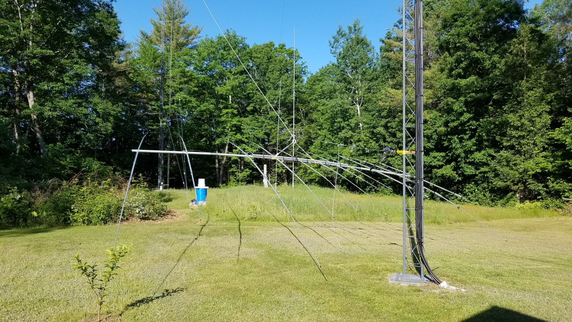
TH11DX on the tram line.Another view of TH11DX on the tram line.Closeup of rigging for TH11DX tramming.TH11DX at the top of the tram line.Final installation, TH11DX at 98 feet, OB1-4030 at 108 feet.
I was concerned about interaction between the TH11DX on 15 meters and the OB1-4030. I had chosen to start without a 90 degree offset to see what happened. I see no detrimental affect. The TH11DX still has a good pattern on 15 meters (and all other bands), SWR is fine, and from what I can tell it is working as well as it has all along. I got away with it!
The last of this work was completed with snow on the ground. As of December 2021 I still have some work to do on low band receive antennas which have somehow managed to develop issues during the a period of disuse. Other than that, all damage has been repaired. 160 meters through 70 cm are back up and running. The loan was a necessary evil but unfortunately it means very limited new projects for a while. During the course of this project, May through December, with great effort and force of will, I was able to lose 40 pounds. By the end of the project my comfort climbing was as good or better than it has ever been.
I have been on VHF weak signal (meaning primarily CW and SSB operation and later digital) most of the time since 1986. I took a few years off between 2007 and 2016 but have put major effort into returning since then. During my years on VHF I have been active in most of the VHF contests.
My reasons for being involved with ham radio and the activities I seek out within the hobby may be different than most. I have always been fascinated by radio and I love DXing but this is also a much needed coping mechanism and stress relief for me. I am on many bands and modes because variety is key to getting what I seek out of this.
Several things made VHF operating and contesting different from HF. First there was propagation. On VHF there are a variety of propagation mechanisms including troposcatter, tropo, meteor scatter, aurora, sporadic E and if one has a capable station, EME. Each propagation type has its own unique characteristics and may impart a variety of effects to the signal. There is the characteristic flutter of meteor scatter, the hiss of aurora, libration fading on EME. Troposcatter signals can sound perfectly normal or they may have rapid flutter or even multipath effects. I loved hearing all the unique sounds. I felt connected to a variety of fascinating phenomena that made a signal go from here to there, learned to identify each of them and how to best exploit them. It was all part of the magic and wonder of radio.
Sometimes VHF signals are very weak. I love the challenge of digging out a weak signal by ear on CW or SSB, figuring out how to best adjust the length and timing of transmissions to get that weak one in the log.
In VHF contests one would get to know the other players. Every contest there were familiar voices on SSB and “fists” on CW. Even in the heat of battle, many would take a minute to say hi and exchange a brief remark or two. Sometimes one could get information about activity or propagation conditions that proved helpful. This was a thoroughly unique and enjoyable aspect of VHF contesting for many years.
VHF contests also provided a unique opportunity to make contacts on bands above 2 meters. Generally there is little to no regular activity up there, but many VHF contest stations have more bands and of course they wanted to work others on as many of them as possible. Generally one would work a station in 2 or 6 meters and make arrangements to QSY or “run the bands” with them. This was great fun and really made having higher bands worthwhile. If it weren’t for VHF contests I probably never would have ventured above 2 meters. Sometimes the challenge for me would be to run through several bands quickly to take advantage of a short propagation peak. I am pretty far from most of the VHF activity, so making the most of propagation peaks was important.
VHF contesting has changed a lot in the last 35 years. One of the most obvious changes is the decrease in activity. Twenty or thirty years ago I could get 70 to 90 QSOs on 2 meters in a VHF contest plus a good number on any other bands I had at the time. Except perhaps for a few hours between midnight and dawn, there were always signals to be heard on 2 meters. In contrast, for the past few years I have a more capable 2 meter station than ever before but no matter how hard I work at it, 30 QSOs on 2 meters was about all I could hope for. I was lucky if I got a dozen each on 222 and 432 MHz and whatever number on 6 meters depending on long range propagation which is far more prevalent there. There were long periods of time when no signals were to be found on 2 meters. Almost all of the big stations are gone now, so QSOs around the 500 mile mark (generally the limit for CW or SSB between well equipped stations under average band conditions at 2 meters and above) have become rare. Despite the sharp decline in activity I was still enjoying VHF contests. The longer distance contacts were all the more special and exciting since there were so few to be had.
Then came FT8. This is where my love affair with VHF contesting began to fade. It’s not that I hate FT8. I have used FT8 in previous VHF contests, day to day on VHF outside contests, and on HF. It can be a lot of fun and in some ways it is a better mode for me. Just days prior to the 2022 January VHF contest I ran piles of JA and Asia on 40 meter long and short path and had fun doing it.
The VHF contest activity that used to be on SSB and CW has been shifting more and more to FT8. Mainly this is on 6 and 2 meters while there is little to nothing going on above that. FT8 has brought many newcomers to VHF and contesting. I don’t argue that more activity is a good thing, especially in light of the decline in VHF activity over the past 20 years. Unfortunately it comes at the cost of nearly eliminating activity on traditional modes. For me this has mostly killed the uniqueness and fun of VHF contesting.
The personal connection to VHF propagation phenomena is gone. With FT8 signals are either too weak to hear, or there are several signals and it isn’t possible to hear the unique characteristics of those that are undergoing propagation curiosities. The magic and wonder of it all is gone. It isn’t possible to adapt timing, speed or length of transmissions to compensate for propagation anomalies, as all of that is locked into a fixed format. It is also common to lose contacts to QSB that I know I could have completed on SSB or CW. FT8 contacts take too much time to ride the sometimes short peaks.
For the most part the connection to people I know is gone. While it is possible to exchange a very brief remark on FT8 it is cumbersome and few do it. You need to be a lightning quick typist. It’s not the same as hearing a familiar voice or CW sending style. I find it sterile.
Making arrangements to run the bands is harder with FT8. I know some have had success with it and there is a new technique now being proposed or tried that might help somewhat. But still, I think it is much harder with FT8 than it was with SSB or CW. Also, you either need to first QSY to SSB to make arrangements, or try to run the bands on FT8. Either way takes longer than the quick, snappy band changes and QSOs one could make using traditional modes. This is not good for me. Being far away from most of the activity I often depended on running through the bands quickly to get those contacts during a short tropo peak.
I have tried to get something unique and special out of FT8 on VHF but have not succeeded. The unique feel of VHF contesting has been lost. Without that uniqueness I am losing interest. Prior to this FT8 transition, I would prioritize VHF contesting over HF contesting or DXing because it was unique and fun. Now, with what was unique and special about VHF nearly gone, I get more benefit out of chasing DX half way around the world on HF than I get from participating in a VHF contest. That is the bottom line. It may be true that at some point during a contest there is a small amount of activity on other modes, but listening to white noise for hours to catch 10 QSOs is not fun nor is it helpful to me in other ways. That is too little return on investment of my time, to say nothing of money tied up in a VHF station. After listening several times in the recent 2022 January VHF contest and hearing mainly FT8 on 6 and 2 meters and nothing on higher bands I voted with my band switch. I went to HF and worked DX half way around the world because I got more out of that than I would have working the VHF contest.
This isn’t the first time I have felt the rug had been pulled out from under me on VHF. My years of absence from VHF between 2007 and 2016 were precipitated by EME going from CW to JT65. I had spent a fortune and a great deal of time building up my EME station only to have the fun and benefits suddenly vanish. Since EME was no longer providing what I seek from the hobby I dismantled the station and sold everything off in order to build a better HF station. That was a necessary move. It took some time to regroup and begin rebuilding VHF with an emphasis on terrestrial operation and contesting. Now VHF contesting and operating in general seems forever changed by FT8.
Change is inevitable and the VHF world has moved on. Currently there is some discussion about changing VHF contest rules to encourage more SSB and CW activity. Even if changes are made, I have my doubts that it will actually revive use of those modes. There was some tinkering with EME contests after the digital revolution but did it bring back CW? For the most part, no. In the end I hope the influx of new blood brought about by digital modes proves a positive thing for ham radio, but I think we have to accept that any change which drastically alters the very nature of an activity will inevitably result in losing some, like myself, who came to and enjoyed that activity precisely because of its unique nature.
I would not presume to think of mine as a big station, though with 1500 watts on 6 and 2, 800 watts on 222 with long yagis 100 plus feet in the air it is not exactly small either. I have a high and long yagi on 432 but lack power there. If one were to consider this a big station then I guess am just the next to fall. I am not sure whether I will leave VHF altogether but one thing I do know beyond a reasonable doubt. Had I known in 2016 where we would be just five years later, I would not have made the effort to return to VHF. Building the station was a genuine hardship and involved many sacrifices. I wish I had that money back to pursue other interests where there is still something of personal value to be gained. With the changes occurring on VHF I find myself thinking about what other antennas I would have room for if I removed all of the VHF antennas from the tower. I am deeply saddened that we have come to a point where I would even consider that after all I went through to build the VHF station, but here we are.
This is one of a series of “Notes” I published on Facebook. Since Facebook has discontinued the Notes feature, I am publishing that series here on my blog.
It was early morning on the 28th day of March, 2018. Most people were sound asleep but not me. I was in my ham shack, hands trembling, heart pounding as I typed a few letters and numbers into my logging program. I could barely breathe. I had just completed one of the most exciting QSOs of my nearly four decades chasing DX. This single QSO cost more money and time than any other I had ever made. It was a QSO with England. You may wonder what is so exciting about that when any ham with five watts and a piece of wire can contact England from Maine. Well, this was special because we did it on the 2200 meter band. It was the first amateur radio USA to Europe QSO on what is, for us, a new band. This was no easy feat. It required months of station building and four nights just to complete the QSO. Some would call it a ridiculous folly and see no sense at all in it. But to me this is the true spirit of amateur radio, finding a way to communicate against the odds, adapting equipment and technique to accomplish the desired result. It is man and his machine against nature, determined to succeed under the most difficult circumstances.
The 2200 meter band allocation is 135.7 to 137.8 kilohertz in the long wave part of the radio spectrum known as LF or low frequency. In some ways this goes back to amateur radio’s early roots on 1750 meters, but it had been more than 100 years since U.S. amateurs were allowed to transmit in this part of the radio spectrum. These frequencies are not easy! Normal size antennas would be huge. A half wave dipole would be 3400 feet long; a quarter wave vertical towering to a height of 1700 feet. Natural and man made noise tend to be very high in this part of the radio spectrum and ionospheric propagation is feeble compared to the short waves. On top of that, we are only permitted to run one watt effective isotropic radiated power (EIRP). That is flea power compared to what we can use on most any of our higher frequency allocations! By comparison, when I was doing EME (moonbounce) on the two meter band I was legally running about 450,000 watts EIRP. But ham radio DXers who like a good challenge can be a very determined lot. The greater the challenge, the greater the reward.
I became interested in 2200 meters in late 2016 after the local club asked me to prepare a report on this and the 630 meter band, which were expected to soon be opened for amateur radio use in the U.S. At that time the only way to legally transmit on either band was to get a Part 5 FCC license under the experimental radio service. One could almost write one’s own ticket on power limits and frequency allocations but this wasn’t amateur radio. I did apply for and was granted a Part 5 license but never used it since FCC opened these new bands to amateurs just as I was getting a station put together. I found receiving on 630 meters to be relatively easy, if somewhat plagued by noise and available antennas. But 2200 meters was a very different thing. It took weeks of experimentation and testing to detect the first trace of signal on this band. Many weeks later after more trial and error I was rewarded with my first reception of a ham radio signal from Europe on the band when DC0DX appeared in my WSPR decodes. I confess it was then that I first started to dream of someday making a two way QSO across the Atlantic on long wave.
I thought I had plenty of time to build a station, since the FCC process on opening these bands had been dragging on for years. But in the Spring of 2017 the announcement came that we would get these new bands in a few months! Now the race was on. I frantically began building transmitting apparatus. I didn’t quite make it for opening day in October but I was on the band a few weeks later. Early amplifiers were plagued by budget shortfalls and poor performance. By mid February, 2018 I had managed to achieve 0.5 watt EIRP, just three decibels below the legal limit. The flood gates opened and to my amazement I started receiving numerous WSPR decodes from European stations. Wow!
I believed a two way trans-Atlantic QSO was in my future but was not sure when. I was eager for an attempt but still very much struggling with equipment and budget. I was hearing stations from Europe. Stations from Europe were hearing me. But for the most part, those who heard me did not have transmitting capability or not sufficient to reach across the Atlantic. The best bet would seem to be 2E0ILY. We had conducted tests earlier in the season and I could often copy his JT9 beacon. Chris could occasionally copy my WSPR signal but not at sufficient strength for JT9 to be viable. I knew there were ways to get it done, but this would take several nights. I was hesitant to ask anyone to commit such effort and time to a QSO.
As the relatively quiet season was drawing to an end I realized another season is never guaranteed for any number of reasons. I had given the matter considerable thought. There were no practical digital modes which would work with the low signal levels involved. Two old school modes came to mind: QRSS and DFCW. Both are very slow, trading time for weak signal detection capability. QRSS is extremely slow CW, so slow in fact that it can only be copied by reading it off a computer screen. In this case, a speed of QRSS60 would be best, meaning that each dot would be 60 seconds in duration. A dash is three times as long, just as in normal CW. This mode requires nothing special for equipment, as it uses on/off keying of a carrier and is fairly tolerant of frequency drift. But, the shortest element, the dot, sets the achievable signal to noise ratio. There is no advantage gained from the dashes being three times as long, so it is essentially time wasted. Time is valuable, as signal fading means you have a limited amount of time to copy the message. DFCW, or dual frequency CW is an offshoot of QRSS in which dots and dashes are the same length but sent on slightly different frequencies so that one may be differentiated from the other. This saves considerable time with no reduction in signal to noise ratio but requires more complex transmitter keying and reasonably tight frequency stability. In a typical DFCW60 transmission, the dot to dash frequency shift is a small fraction of a hertz. Transmitter and receiver drift must be held to less than this in order to avoid dot-dash ambiguity at the receiving end. It would take about an hour to send two call signs at DFCW60 speed. It was now late March. Clearly there would not be enough common darkness between Maine and any part of Europe to allow a QSO to be completed in a single night at this speed.
It may be useful to consider what is a QSO. These days the term means different things to different people. I came up through the DXing ranks with what is now a somewhat old school definition for a minimum acceptable information exchange to claim a QSO under very weak signal conditions. I still firmly believe in the old way, as we are after all supposed to be communicators. That definition is that each station must receive from the other both call signs, signal report or other piece of information, and acknowledgment. This requires that two transmissions be copied in each direction. Anything less than that does not seem like communication to me, and leaves me with no sense of accomplishment.
It seemed the best way to go about it would be to borrow operating and reporting techniques from EME, modifying procedure slightly to account for the much longer period of time required to send a message on the long waves. In this procedure, the letter O would be used as a signal report to indicate full call signs had been copied; R and O would be used to indicate full call signs plus signal report had been copied; R by itself to indicate call signs, report, and R (as part of R and O) had been copied. As for timing, it seemed sensible to use night by night sequencing. That meant the two stations would take turns transmitting, one going the first night the other the second, alternating back and forth throughout the QSO. It would take a minimum of four nights to complete a QSO, assuming the full message could be copied each night. If it wasn’t, additional nights would be required for repeats. That’s really slow! But it did offer some advantages with the equipment available. In order to achieve the required frequency stability I would have to use my QRP Labs Ultimate 3S beacon transmitter. The U3S is a great piece of gear, but editing messages is tedious. Night by night sequencing would give me all day to change the message for the next night’s transmission! A complete QSO would look like this, where bold indicates my transmissions, italics indicate transmissions from the other station:
2E0ILY N1BUG N1BUG 2E0ILY O RO R
Meaning of the first line is obvious. I am transmitting both call signs. In the second line my QSO partner adds the signal report, O, to let me know he had copied both call signs fully. In the third line I send RO which means I have copied call signs and my report, your report is O. In the last line my QSO partner sends R, meaning I have copied all on my end. When I copy the R the QSO is complete. If a message is not copied, or not enough information is copied, then one continues to transmit the previous message until getting something back which advances the QSO.
I had worked out a viable technique. Now I just needed a QSO partner. Just in time I worked up the courage to ask Chris, 2E0ILY if he would be willing to give it a try. I was very happy when he said he’d have a go at it.
We had decided I would transmit the first night, so I set the U3S to send ‘2E0ILY N1BUG’ over and over during the hours of common darkness between our respective locations. It turned out to be an ugly night in terms of weather. I was getting heavy wet snow squalls. Nothing causes a 2200 meter Marconi antenna (vertical) to go out of resonance any quicker than wet snow! These antennas are electrically short and require huge loading coils to resonate them. They are high impedance antennas and the bandwidth is very narrow. These antennas are prone to changing characteristics on a whim. Every time the snow started, stopped, changed intensity or the amount of snow clinging to the antenna changed, the thing went wandering up or down the band and required retuning for resonance on the operating frequency. Fortunately the variometer at the antenna base was motorized and I could adjust it from the comfort of my transmitter room. But I had to keep a constant vigil, watching antenna resonance and adjusting as needed. I had my finger on the switch for variometer adjustment far more than not. After a while my fingers were getting sore from constantly manipulating the tuning switch. Perhaps I shouldn’t have used a miniature toggle switch there. If you think this was an automated QSO without operator involvement, think again! My presence and diligence at the controls was absolutely vital that night!
Message copied from 2E0ILY on the second night of the QSO (annotated). Note dots on the lower frequency, dashes shifted 0.187 Hz higher. When the signal is this strong, elements tend to bleed together a little but since they are of fixed length it is still very readable.
The next night it was my turn to listen. Due to the extremely slow speed DFCW is copied visually using software designed for this purpose. Anxiously I stared at the screen. When I wasn’t nervously pacing, that is! I began to see traces of signal, then an odd letter here and there. There was a B, a 2, a Y and I even thought I saw an O but couldn’t be sure. Eventually conditions stabilized and I began to get steady print on the screen. Waiting 60 seconds for a dot or dash to fully paint on the screen can be agonizing. Slowly the elements accumulate and become characters. If you are lucky, propagation holds up long enough to copy the full message. Fortunately, after somewhat of a slow start copy remained solid and I eventually had N1BUG, 2E0ILY and a very nice O painted on my screen! I had copied full call signs and a signal report indicating Chris had got full call signs from me the previous night! We were half way there!
The third night I was transmitting again. Since I knew Chris had already copied full call signs from me, it was not necessary to transmit them at this stage of the QSO. Technically I could have just sent RO repeating throughout the night, but being of the cautious type I decided to include call sign suffixes to provide positive evidence the correct station was being copied. Thus the message I transmitted was ‘ILY BUG RO’. This was a risk as it takes far longer to send than simply ‘RO’ and signal fading can be a huge factor. At least the weather was better and I didn’t have to ride the variometer all night.
Soon it was night four, back to pacing and staring hopefully at the screen. I was especially nervous that night, as I had some strong, drifting interference right on top of Chris! Finally it moved just enough that I could make out ‘BUG ILY R’. There was rapid fading and the dash in the R was much fainter than the rest. Fainter but unmistakably there. I was positive about the R but being the cautious type and realizing this QSO would be an amateur radio first I really wanted to see it more clearly before declaring the QSO complete. The signal faded and nothing was seen for hours. Sunrise at 2E0ILY was fast approaching and I had to make a decision. Was I going to log the QSO or retransmit my RO message the following night in hope of getting better copy of the R on night six? Just before dawn the signal reappeared, very weak. I could barely make out ‘BUG IL’, then the ‘Y’ was quite strong. Given the proximity to sunrise every minute felt like an eternity. Ticking of the clock became offensively loud. It was going to take another four minutes to get an R! Would it hold up that long? Slowly, as the clock ticked and my heart raced, a crystal clear ‘R’ painted on the screen. There were traces of signal for some time after that but nothing I would call readable, save a stray ‘Y’ that somehow came through well past dawn. So it came to be that shortly after 0600 UTC (1:00 AM local time) on this, the 28th day of March, 2018 I entered this QSO into my station log. We had done it!
QSL card received for this very memorable QSO!
This was an amateur radio first from the U.S. but nothing new in terms of distance on the 2200 meter band. Canadian stations, operating under amateur call signs but otherwise a program similar to our Part 5 licenses, had worked Europe years earlier. Much longer distances had been covered. But for me this was one of the most exciting QSOs of my nearly 40 years as a DXer. It ranks right up there with my first EME QSO, the QSO that put me on the DXCC Honor Roll and several other notable events such as being credited with the first North American two meter auroral E QSO back in 1989. My thanks to Chris, 2E0ILY for his time and patience to make this happen – not to mention the kilowatt hours of electricity expended.
DFCW may be old school but it gets the job done under extremely difficult conditions. DFCW ‘decoding’ is done by the human operator. Deciding what has been copied is not left to computer software which may use assumption or non amateur radio means to fill in things it couldn’t positively make out over the air. DFCW is painfully slow but here we had a very positive over the air exchange of full call signs, reports and acknowledgement without any shortcuts or fudging. I was very pleased with that!
Although this single QSO cost more than any other, this was a low budget operation. Most of the LF station consists of low cost kits and home built gear. Equipment used at my station for this QSO was the QRP Labs Ultimate 3S driving a home built amplifier to 175 watts output. The transmitting antenna was a 90 foot Marconi (vertical) with a top hat consisting of three wires each 100 feet long, spaced five feet apart. Three one inch diameter aluminum spreaders plus triangular wire sections at each end are electrically part of the top loading. This is resonated at the base with an inductance of approximately 2.3 millihenries. Loss resistance at the time was near 100 ohms, resulting in EIRP of 0.5 watt. For receive I used a 30 foot low noise vertical, band pass filter, W1VD preamp, and a modified Softrock Lite II SDR receiver.
This is one of a series of “Notes” I published on Facebook. Since Facebook has discontinued the Notes feature, I am publishing that series here on my blog.
I have been listening on 630 meters for over a year and I had operated a WSPR beacon two previous nights with very low power of about 15 milliwatts EIRP (Effective Isotropic Radiated Power). Even at that power level I was heard by more than 25 stations at distances to beyond 1000 miles, 1600 kilometers. But last night as winter descended upon the region with the first significant snowfall, I was transmitting with 22 watts TPO (Transmitter Power Output), resulting in about two watts EIRP. That is still four dB below our legal limit of five watts EIRP. Results were better than I expected for my first night, even though propagation was certainly not at its best!
At times I am a rabid contester, an avid DXer, an experienced builder of antennas and equipment. I love radio. I enjoy all of these activities but if I had to describe my pursuit of radio in one word it might be explorer. I love trying something new, venturing into little used territory, pushing limits, trying to beat the odds. I have a well equipped station. I could easily converse with amateur radio operators around the world most days just by turning on a radio and speaking into a microphone. Instead I am driven to pursue nearly impossible contacts on frequencies that do not easily go the distance. I especially enjoy pushing the limits of propagation, equipment and myself as an operator on modes where the human ear/brain is the decoder. Unfortunately that is becoming a rare thing in today’s world of digital modes where the computer does the decoding, all too often using only partial information received over the air, the rest filled in from a database or assumed because it was information previously known to the decoder. The continuing erosion of what represents a two-way amateur radio contact saddens me beyond words. Nevertheless I continue to find joy and excitement in the exploration of frontiers which, if not new to mankind, are new to me. I regret only that there will not be enough time to explore all there is to see and do in radio.
So it was that little more than a year ago I began my quest to conquer the two new low frequency bands, 630 meters (472 to 479 kHz) and 2200 meters (135.7 to 137.8 kHz). I spent the first winter learning about and building receiving equipment for those frequencies. There was a learning curve and I had to find what worked within my budget. Mission accomplished.
In the Spring I set my sights on building a transmitting station but quickly ran into a setback. The only way to put up a reasonably efficient antenna in the space I have would be to support it between my two existing towers. It didn’t take long to discover the older, weaker tower would not stand the strain of such an antenna! There was only one thing to do: replace the tower! The search for materials took all summer and the project wouldn’t have been possible at all without a great deal of help from friends. The work began in October and was not complete until the middle of November. That left little time before the onset of winter to build the antenna, a transmitter, and all the associated things that go with it. The antenna, a Marconi-T made of wire and strung between two towers, is shown in the cover photo.
One has to get into a very different mind set about antennas at these frequencies. Most of us are accustomed to “full size” antennas – dipoles, verticals, loops – which radiate nearly all the power we put into them. In many cases we use directional “gain” antennas that actually make our effective power more than we have coming out of the transmitter – in a favored direction. Very few if any will be able to reach anything approaching 100 per cent efficiency at 630 meters and no one will at 2200 meters. Forget about gain antennas! Horizontal polarization does not work well at these frequencies. A quarter wavelength vertical for 630 meters would be 490 feet (149 meters) tall and for 2200 meters, 1700 feet (520 meters)! Not only that, but unless located over salt water a vertical needs an extensive system of ground radials around it to be efficient. Most amateur antennas at 630 meters will radiate no more than a few per cent of the power fed to them, while many will be less efficient. At 2200 meters reaching one per cent efficiency will be very difficult for most, impossible for many. My 90 foot (27 meter) tall vertical with three 100 foot (30 meter) horizontal top loading wires sits over a radial system with more than 10,000 feet (3048 meters) of wire in it. Yet the best I can hope for is 3% efficiency on 630 meters and 0.25% efficiency at 2200 meters. The vast majority of power is eaten up by ground losses and losses in the large loading coils needed.
In fact, once we cancel out capacitive reactance due to the antenna being electrically short, the resistance we see isn’t really the antenna at all – it is dominated by loss resistance! Even at 630 meters the radiation resistance of a typical antenna will be an ohm or two, in many cases less. Even very good ground systems will be many ohms. My radiation resistance on 630 meters is 1.25 ohms. I measure 39 ohms when the antenna is resonant. Almost all of that is the ground system loss resistance, and that is where most of my power goes! This really is a different world from the higher frequencies.
The challenge doesn’t end there. After we manage to get a few watts radiated, we have to contend with the fact the ionosphere doesn’t propagate signals at low frequencies as well as it does higher ones, while both atmospheric and man made noise is much worse down here! It’s a wonder we manage to communicate at all. But we do. That’s the challenge, and that is what attracted me to this.
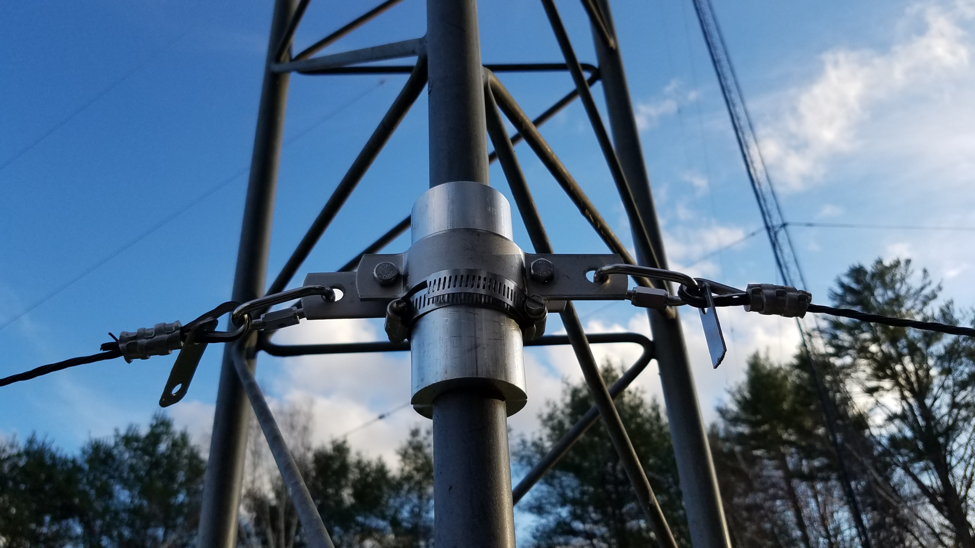
The variometer (left) is an adjustable inductor used to cancel out capacitive reactance in the antenna and resonate it on the desired freqeuncy. The matching transformer on the right steps up the resistance of the antenna system (in this case about 39 ohms) to the 50 ohm impedance of the feed line and transmitter.
By midday December 9 I was ready. The antenna was up, the variometer adjusted, matching transformer properly configured and my little 25 watt home made transmitter was ready to strut its stuff. I set it to transmit as a WSPR (Weak Signal Propagation Reporter) beacon, sending out a two minute standard WSPR message every ten minutes. In broad daylight, I received several reception reports after my very first transmission! WSPR reception reports are available on the Internet almost immediately and may be viewed as a list or displayed on a map.
The transmitter, consisting of a QRP Labs Ultimate 3S exciter (assembled from a kit) on the left and home made amplifier on the right.
I spent the first few hours nervously checking the transistor in the amplifier with my finger to see if it was running too hot, watching squiggly green lines on the oscilloscope for any sign the antenna was drifting off frequency or something breaking down outside. To my joy all continued to look good! It was not as if I had no reason to wonder. One transistor had died weeks earlier during initial testing of the transmitter. That occurred while running into a perfect resistive load, not an antenna that might be imperfect or change on a whim. These low frequency antennas which are, of necessity, electrically short actually can change on a whim! The capacitance and hence resonant frequency can change as they sway in the wind. The resistance can change with weather and season. With several inches of snow forecast for the night, I didn’t know what to expect. So I nervously watched over the system. After every transmission I checked to see where I had been heard.
As sunset approached and passed, the band naturally stretched out. I began to get stronger signal reports and was being heard at ever greater distances. After some time there was a report from a station in the Netherlands! My puny signal had made it all the way across the Atlantic on a frequency below the AM broadcast band! This was soon joined by reports from the Cayman Islands and Canary Islands. Africa! Toward morning I even got a reception report from Hawaii! Just before dawn I observed some variations in the antenna system. The two sine wave patters on the oscilloscope display began shifting slowly, almost rhythmically back and forth with respect to one another. This was caused by changes in antenna capacitance as it swayed slightly in a gentle breeze. I have heard the effect described “as if the antenna is a living, breathing entity” and I would have to concur with that description. It was fascinating to watch. I got very little sleep and didn’t even notice it was one of the longer nights of the year. I was having too much fun! I was exploring!
Oscilloscope patters from the “scopematch” monitor the antenna resonance and resistance. If the antenna were perfectly resonated on the transmitting freqeuncy and perfectly matched to 50 ohms these two sine wave traces would converge into one. Here, one is shifted to the left slightly, indicating an off resonance condition (in this case exhibiting inductive reactance), and they are not of the same amplitude (height), a sign of imperfect resistance match (here showing the resistance to be slighty high).
There are many challenges and new experiences yet to come on the low frequency frontier. One of my winter projects will be to build a transverter so that I can transmit modes suitable for two way contacts. But the bigger challenge is getting operational on the lower frequency band, 2200 meters. The coil and variometer will be much larger, creating not only issues in construction but in protection from weather. The antenna impedance will be far greater, resulting in very much higher RF voltage and the possibility of interesting but unwelcome events such as insulation breakdown, arcs and corona! Undoubtedly the antenna will “breathe” to a much greater extent. On 2200 meters I expect a lot of action on the scope when there is any breeze.
This is one of a series of “Notes” I published on Facebook. Since Facebook has discontinued the Notes feature, I am publishing that series here on my blog.
Woo-hoo! What a fun event! This was the first time in some years I had a good station for two meter DXing such as meteor scatter. I wanted to have some fun and see what I could work with it. This is undoubtedly the best setup I ever used for meteor scatter, due mostly to the antenna height. I am running 1500 watts to a 13 element YU7EF yagi at 110 feet (33 meters). However several factors re not ideal. The feedline is good cable but long with about 2.5 dB loss. I don’t have a mast mounted preamplifier so my receive may not be optimum. My location is not the best. I am in a small valley next to a river. Given antenna height, my horizon in the most important direction, southwest, ranges from about +0.0 to +0.5 degree.
I was able to complete some QSOs more than 1200 miles (1930km) on random in response to my CQ. My best distance this shower was also my all time best personal meteor scatter DX record with KC4PX at 1334 miles (2146km). Ivars heard a lot more from me than I did from him but there was a 6dB power difference. He was running 350 watts to a single yagi antenna. His best signal here was +6, which is some 10 dB above the minimum that I can decode. This not only gives me a new personal MS DX record, but also hope for longer distances in the future. It took 47 minutes to complete the QSO but it was time well spent! Ivars also heard me at several other times during this meteor shower. My horizon is +0.3 degree at the exact heading to KC4PX.
N1BUG 144 MHz MS QSOs for Perseids 2017
The meteors were best between approximately 0300 UTC August 12 to 1700 UTC August 12. During peak times some random QSOs could be completed in the minimum number of 15 second sequences, including W0VB at a distance of 1162 miles (1870km). This was not one long burn, but a collection of smaller meteors that allowed us to transfer needed QSO information in every 15 second slot.
I cannot say for sure that it was one long burn but I had three consecutive full 15 second periods of N4QWZ with two of my transmit periods in between. If this was one long burn as it appeared to be from signal quality and characteristics, it was more than 75 seconds!
I made 22 meter scatter QSOs in 13 states. It seemed odd that I didn’t work any Canadian stations. I did not count grid squares.
I can hardly wait for the next major meteor shower! You can be certain I will be pushing for longer distances in the future. I should be able to extend the distance with a full legal power station at the other end.
This is one of a series of “Notes” I published on Facebook. Since Facebook has discontinued the Notes feature, I am publishing that series here on my blog.
Note: I may add illustrations later, but want to get this out before the peak of the 2017 Perseids meteor shower.
You’re staring into the night sky when all of a sudden a streak of light appears. It’s caused by a meteor burning up as it enters the Earth’s atmosphere at high speed. It may be no bigger than a grain of sand but it makes quite a show. There may very well be a ham radio operator somewhere trying to bounce a signal off that meteor trail.
Since the 1950s, VHF ham radio operators have been using ionized meteor trails to reflect their signals beyond normal everyday range. While the tools and methods used have changed over the years, meteor scatter remains a popular method of communication. I mentioned this propagation mode only briefly in previous VHF weak signal operating primers, so let’s take a closer look at it.
What is meteor scatter good for? It’s not a ragchew mode. At 50 MHz the ionized trail may only be capable of reflecting the signal for a fraction of second, or it could be up to a couple of minutes in extreme cases. The higher you go in frequency, the fewer meteors capable of supporting propagation and the shorter the signal duration. At 144 MHz anything over 30 seconds is relatively uncommon but some may last a minute or so. There are still fewer meteors capable of supporting propagation at 222 MHz. Only the biggest and fastest provide very brief propagation at 432 MHz. Most of the time, several meteors will be needed to complete a “minimum QSO”. So just what use is meteor scatter? Using special techniques, it is possible to work stations over distances up to 1400 miles. Meteor scatter is a good way to get more states, grid squares, or just make some nice longer distance contacts on VHF. It can be fun and exciting!
Let’s define what we mean by “minimal QSO”. Long ago it was decided that a valid contact needed to demonstrate some basic level of capability to exchange information (communicate) over the air between two stations. The agreed upon standard was that for a QSO to be valid the following information had to be exchanged in both directions: call signs, signal report (or other piece of information such as a grid square) and acknowledgement that the report was received. This means that if I am trying to make a QSO with W1XYZ, I must hear his call sign and my own. I must hear a signal report and I must hear some confirmation (usually “roger” or RRR) that he got the signal report I sent him. W1XYZ must receive the same information from me.
In meteor scatter you don’t hear the other station all the time. Far from it! Signals come and go erratically in short bursts. In order to make maximum use of available meteors and prevent both stations inadvertently transmitting at the same time, a special operating procedure has evolved. Stations take turns transmitting. In North America the transmit and receive periods are usually 15 seconds each. This requires accurate clocks. During a scheduled QSO attempt, both stations initially start out sending call sings over and over during their assigned 15 second periods. When one station copies call signs, that station will start sending a signal report with call signs. Assuming the other eventually copies both call signs and a signal report he will send acknowledgement that he got his report (usually just R) and a report. When all of that is copied at the other station he sends RRR. The QSO is technically complete when this RRR is copied but since the station sending it has no way of knowing it has been heard, typical procedure is for the one who receives RRR to send 73. Reception of 73 lets the other know all is complete. If you end up sending RRR and never receive a 73, you won’t know if the QSO is complete unless you check with your QSO partner by some other means such as email or an internet chat site. If he got the RRR it is a valid QSO. The honor system is very much in play here. This sounds far more complicated than it actually is. You get used to the process after a few QSOs. The process for a non-scheduled contact (where one station was calling CQ) is similar. Theoretically, using 15 second transmit/receive periods, a QSO can be completed in just over a minute. On 50 MHz it sometimes works that way. On higher frequencies it usually takes longer and sometimes even after 20 or 30 minutes there haven’t been enough meteors to complete the QSO exchange.
In years past, using SSB or CW the procedure followed that form exactly. Once a QSO progressed beyond a need to hear call signs, they were omitted from the transmissions. Most of the time this worked OK. One could often tell from the voice or speed and “fist” that the correct station was being copied. With digital modes, call signs or an abbreviated form of them is usually sent at each stage of the QSO along with whatever info is required at that point. This helps to make sure you are copying the intended station and not someone else.
You may be thinking this sounds like a lot of work just to exchange enough information to log a contact. Maybe you wonder what is the point. To the person who just likes to talk this method of communication makes no sense. But for those who enjoy a challenge, are chasing states or grid squares on VHF or just looking to do something few hams even realize is possible, meteor scatter can be very interesting and rewarding! There is a thrill in that signal suddenly appearing out of nowhere. Completion of any given QSO attempt is by no means guaranteed. Some attempts succeed, some fail due to insufficient number of meteors capable of supporting propagation or other factors. Every completed QSO feels like an accomplishment — because it is!
Meteor scatter has both predictable and unpredictable qualities. Sporadic meteors (those not associated with any particular meteor shower) are best in the morning hours around dawn and shortly after. Relative velocity is also usually higher in the morning unless the meteor is on a path almost parallel to that of the Earth. There are enough of these sporadic meteors to permit QSOs on 50 MHz every day of the year. Winter can be tough going on 144 MHz but most of the year every morning works to some extent. Several major meteor showers each year provide greatly enhanced opportunities on those bands along with the possibility of 222 and 432 MHz. Most notable are the Perseids in August, Leonids in November, Geminds in December and (though of very short duration) Quadrantids in January. There are several other meteor showers that don’t compare to those but nevertheless elevate meteor counts well above the sporadic rate. Regardless of season, time of day, or the presence of a meteor shower, exact meteor rates, burst duration and timing can never be known. You may get 30 bursts in a 10 minute period and not a single burst in the following 10 minutes. You never know. This unpredictability adds to the fun and challenge. During meteor showers there are optimal times of day for specific directions. This has to do with geometry of the intended communication path and the meteor trail angles which change as the Earth rotates. This was much better known and utilized years ago than it is now. Most operators today just take their chances at whatever time they feel like operating.
What kind of station do you need to work meteor scatter? On 50 MHz, 10 watts to a three element yagi will get you started. 100 watts will do quite well. I have made meteor scatter contacts to more than 1000 miles on 144 MHz with 25 watts and a six foot long yagi, but it is not easy! 100 watts to a 12 foot yagi is a good minimum setup to aim for on two meters. If you are looking to break into the extreme distances, 1300 to 1400 miles, you will need more power and a larger antenna. At 222 MHz, 150 watts to a good long yagi (say something on the order of a 20 foot boom more more) is advisable as a minimum, and at 432 MHz you’ll probably need several hundred watts and a monster yagi or array of several yagis.
WSJT-X software running MSK144 mode is the default for meteor scatter work at the present time, but modes tend to change in the modern era. MSK144 transmits data at such a high rate of speed that call signs plus grid square or call signs plus signal report can be received in a burst as short at 72 milliseconds! This allows QSOs to be completed using much smaller meteors (hence a greater number of them) than SSB or CW did in the past. Almost always this is just what you want but on rare occasions there can be a down side to new methods. You can’t shorten the 15 second transmit/receive periods “on the fly”. It won’t work. So if you get a long meteor burst, say lasting a full 15 seconds, you may only get one piece of QSO information through on it; possibly two if it overlaps the station transmit periods sufficiently.
I am going to digress for a moment to add a couple of historical notes. These may illustrate some of the rare magic that meteor scatter operators never forget.
On SSB (and CW to a lesser extent), an alert operator could “pounce” with a very short transmission if he was hearing the other station right at the end of a 15 second period. This sometimes allowed for a quick back and forth with the whole QSO being completed on one meteor trail. One was always on high alert, ready to pounce! Back in the 1980s I was running a SSB meteor sked with a station in Missouri, about 1250 miles away. We suddenly got a long burn and abandoned the 15 second sequencing to rapidly complete the exchange. I was immediately called by another Missouri station who had been listening in. I worked him and then a third, all on one meteor!
Making meteor scatter QSOs at 1400 miles is usually quite difficult, but it can be done. One time I was running a 144 MHz meteor scatter schedule with a station in Greenland, a distance of just over 1400 miles. This would have been a new country for me on two meters and a new personal distance record. At the time, very high speed CW meteor scatter was the normal method in Europe, while SSB was the standard in North America. European high speed CW was so fast it had to be recorded and then played back at slower speed for copy, even among the very best CW operators. One minute transmit and receive periods were used. The Greenland operator (visiting from Denmark) was set up for high speed CW. SSB was the standard in North America at the time, so I had no means to record and play back CW at lower speed. The Greenland operator agreed to transmit at 40 wpm which I could copy by ear. I was using a memory keyer to send at 100 wpm, slow by the European standard but was the best I could do. As it happened we got almost no short bursts at all and the QSO was not progressing. Suddenly he popped out of the noise and I heard him for a full 45 seconds! That is very uncommon at this extreme meteor scatter distance, and was all the more unusual since I have a small hill in that direction blocking extreme low angle signals. There was nothing I could do. Because of the automation and method, we were stuck with the one minute transmission periods. Had we been doing SSB or even conventional speed CW using shorter periods, with operators doing all the decision making in real time, this would undoubtedly have been a complete QSO. We might have squeezed everything in using MSK144 with 15 second transmit/receive periods. Nothing more was heard during our schedule, so I did not get my new country or personal distance record. However this was an exceptional event and exciting even without a QSO in the log to show for it. In all my years working meteor scatter I have never heard another long burst like that at 1400 miles. I did work Greenland on EME (moonbounce) years later.
Getting back to the present, let me introduce a few more relevant points.
Antennas are generally pointed toward the station you want to work, but the optimum path can be skewed a few degrees to one side or the other. The WSJT-X software calculates suggested headings. It also helps keep you on track during the QSO process because it knows what you should send next based on what you have received. There are pros and cons to digital modes, but at least I don’t lose my voice for three days after the Perseids and Geminids meteor showers!
Meteor scatter can be used at any distance less than the 1400 mile theoretical limit, but under about 600 miles it becomes considerably more difficult with fewer and shorter bursts. This is even more apparent if you have a high antenna or one that has a narrow vertical lobe such as stacked yagis. Being able to elevate the antenna a few degrees above the horizon can help with the shorter distances. 700 to 1100 miles is the easiest range although this may vary somewhat for different antenna patterns, height, etc.
Various online chat pages and scheduling tools are an aid in finding stations to run schedules with. ON4KST chat and Ping Jockey are the most widely used. If you just want to make random contacts (calling CQ or responding to CQs), there are MSK144 calling frequencies for that. In North America, these are 50.260 on six meters, 144.150 on two meters. There is activity on 50.260 almost every morning. It seems random activity on 144.150 has decreased significantly in recent years but some CQs can occasionally be found. QSOs can be completed on the calling frequencies when things aren’t too busy. During periods of high activity there is a procedure for calling CQ on the calling frequency, announcing where you are listening for calls. When you hear someone calling on your listening frequency, you move your transmitter there to complete the QSO. Helpful advice on operating procedures can be found in the WSJT-X User Guide and other references, but if possible you may want to find a local elmer who knows the ropes to help you get going. MSK144 works well with strong stable signals too, so you can test with a local station.
If you have six or two meter capability and are looking for a new challenge or just a change of pace, give meteor scatter a try! It’s not your average ham radio communication but it can be quite rewarding. If you don’t already have it, download the WSJT-X software, version 1.7.0 or later. You will need a computer with a sound card and some type of radio interface. Then listen on 50.260 in the mornings to get a feel for what meteor scatter is all about. Here in the northeast U.S. at least, most activity tends to be between the hours of 6 and 9 AM outside of major meteor showers, and possibly any time of day or night during showers.
This is one of a series of “Notes” I published on Facebook. Since Facebook has discontinued the Notes feature, I am publishing that series here on my blog.
To the DX minded VHF weak signal operator, every contact beyond everyday range is exciting. This is a different world from the HF bands where long distance contacts can be made at almost any time. On two meter SSB or CW, contacts to 200 miles with a modest station and up to 500 miles running high power and a good long yagi antenna are about the every day limit. Beyond this, we need special propagation, which can take several forms: tropo, aurora, meteor scatter, sporadic E. Tropo can theoretically be any distance but only in very rare or special situations can one make contacts beyond 1000 miles or so. The ionospheric modes (aurora, meteor scatter, and sporadic E) have a rule of thumb theoretical maxium distance of 1400 miles based on path geometry with average height of the ionospheric E layer where the reflections take place. Rarely will you work anything beyond that distance, and when you do, sporadic E will probably be responsible. The fact that DX opportunities are less common at VHF is one of the things that attracts some people to it. There is a certain thrill and satisfaction in doing the unusual, the rare, beating the odds.
Many two meter DXers say sporadic E (also known as Es and E skip) is the most exciting propagation mode of all on the two meter band. It sure does get one’s blood pumping! For one thing, this propagation is quite rare at 144 MHz. Just catching one of these openings is an accomplishment. There may be years with a half dozen openings during the late May to early August season, but there can also be years with none at all. When it does occur, sporadic E propagation comes on suddenly, often producing very strong signals. Even with QRP it is sometimes possible to make 1200 mile contacts with ease. I once worked a station in South Carolina who was using a two watt portable transceiver with its built in whip antenna. He was booming into Maine! Openings can last from a couple of minutes to a couple of hours. The casual VHFer is likely to miss most of the openings that do occur. Those who monitor internet propagation reporting sites and/or have their own MUF monitor are are more likely to catch these rare openings.
I usually monitor conditions closely during the season but on the afternoon of June 13, 2017 I had been distracted. I walked into the shack in the late afternoon to find this in one of my browser tabs:
“VHF Propagation Map” uses APRS signals to map two meter openings. This is a classic sporadic E footprint. This site can be found at http://aprs.mountainlake.k12.mn.us/
Wow! I was probably missing a sporadic E opening! Hastily turning on the equipment I heard KE4TWI in Tennessee calling CQ. He wasn’t particularly strong and did not hear my low power call while waiting for the amplifier to warm up. Hearing no other signals I thought I had missed the opening. In fact I did miss an opportunity to work Tennessee and quite possibly further west to Missouri or other states. I began alternating between calling CQ on or near the North American SSB/CW calling frequency, 144.200, and tuning around looking for signals. I was about to give up when one of my CQs was answered by KD4ESV in Florida! This was a very good one, as the distance is 1436 miles. The opening would last for about an hour, but with relatively few operators aware of it I worked only four stations: KD4ESV (1436 miles), WA4GPM (1251 niles), N4TUT (1334 miles), and N4TWX (1283 miles). Nevertheless this was extremely exciting stuff! I was on two meters for more than 20 years the first time around. In all those years I worked beyond 1400 miles just once – to the Florida Keys on extremely rare double hop sporadic E, a distance of slightly over 1600 miles). This was only my second QSO past the “1400 mile wall” without using the moon as a reflector. Coming shortly after my return from a 10 year break it was especially thrilling.
This map shows some QSOs which were reported via the DX clusters. My 1436 mile contact with KD4ESV is shown. We can see contacts from southern New Hampshire to Tennessee and Missouri duing the part of the opening I missed. This map came from https://www.dxmaps.com/
The above map is one of several useful online resources for spotting openings, but it only shows contacts after they have occurred and been reported. Hence there is a lag, and since these openings can be short, in and of itself this is not the best way to spot openings. DX Maps also offers a real time Es MUF map, which may be more useful with a few caveats. The MUF map takes reported contacts on lower frequencies, such as six meters, then computes MUF based on distances and path centers. Suddenly rising MUF over 100 MHz can be an indicator of possible upcoming two meter openings. This is not foolproof. Some operators don’t report (or incorrectly report) the type of propagation when sending DX cluster spots. This can introduce erroneous data to the system, causing unrealistic MUFs to be reported. It can also miss some openings if not enough people are reporting QSOs from lower bands. Nevertheless it is very useful, especially since it can often give an early warning as the MUF starts to shoot up.
The Es MUF map was captured *after* the two meter opening, as the MUF was falling. The “hot spot” showing 111 MHz MUF had been over 160 MHz several minutes earlier, during the time I was working Florida from Maine. Note that this hot spot is at approximate path mid point for those QSOs. This is from https://www.dxmaps.com/
Another very useful tool for spotting potential two meter Es openings is to set up your own MUF monitor in the FM broadcast band. Years ago I had a receiver which I left tuned to a frequency around 90 MHz during the Es season. When I started hearing distant signals exhibiting the strength and fading characteristics common to Es, I would move it to around 107 MHz and keep tuning around that high end of the band. Whenever I heard Es signals there, I would start calling CQ on two meters. The system served quite well for catching these rare openings. These days a wide slice of the FM broadcast band could be visually monitored with a SDR. I would highly recommend this to anyone wanting to work these rare openings on two meters.
This is one of a series of “Notes” I published on Facebook. Since Facebook has discontinued the Notes feature, I am publishing that series here on my blog.
The first week of Technician license classes I tell students amateur radio can be a lifelong journey of learning. For some it is a means to an end, be it providing public service or for personal safety while enjoying other recreational activities. For others it is a hobby but not necessarily something that leads to continuous learning or exploration. Then there are those like me. Maybe I have the heart of an explorer. I am quick to dive into exploring a new band or mode, especially if it is challenging. I appreciate and enjoy learning how to do things.
I am by no means an electronics expert. I am in awe of those who understand microprocessor and logic circuits and those who handle RF and microwave design with ease. I wish I understood and felt confident with those things but I have come a long way from the kid whose first project, a key click filter with two inductors and two capacitors, went up in smoke. Today I am able to solve some design problems on my own and occasionally turn junk into something truly useful. As long as my brain will continue to absorb new ideas I will continue to learn about radio and electronics. Sometimes the things I design use older technology because I understand it. Sometimes it is because that is the least costly way to do it. Sometimes both, as is the case with my current project.
I don’t learn well from books or any form of text. I learn better in a classroom, from videos, or best of all from hands on experience. There has been a lot of magic smoke released from electronics here over the years and I have learned much from doing things the wrong way! Many people have contributed to my ongoing education through the years, but Steve K0XP (formerly KO0U) stands out as the greatest mentor I ever had. Through daily email contact in the late 1990s and into the early 2000s, he tutored me on a wide range of subjects involving solid state analog and basic RF design. Steve explained one thing at a time, patiently repeating and rewording until it was absorbed. I have been thinking about that a lot on my recent design project, as it involves a basic concept I finally “got” through Steve’s efforts: using transistors as switches. The drawers full of transistors from which I pulled stock for this were part of an incredible gift Steve found for me.
I call my latest project FRABS (Fool Resistant Automated Band Switching). Everything here needs to be fool resistant. Otherwise the magic smoke gets let out of stuff. This project would be too simplistic for some, too advanced for others. It is within my comfort zone. I admit the design concept using transistor switches is yesterday’s technology. Some would use opto-isolators, some a microprocessor based design. I use transistors because I understand them, I have drawers full of them and they get the job done.
FRABS is almost harder to explain than to build. Last year I started getting back into VHF and UHF using transverters. I have only one station transceiver, which now has to serve for HF and VHF/UHF. I have more than one amplifier sharing a common high voltage supply, and my antenna switching system is somewhat complex, involving both transmit and receive antennas for HF. If I were to forget to put one amplifier on standby before trying to use another, bad things would happen. I once forgot to disable the HF amplifier and dumped 1500 watts of RF into a hybrid transverter drive attenuator rated 250 watts. Zap! So much for that device. Clearly simple wasn’t going to do it here. Simple can be good, as in keep it simple, stupid. But simple isn’t always fool resistant.
What I needed was some means of automating the various tasks involved with switching bands: route RF to the proper places, enable one amplifier while ensuring that all others are disabled, etc. I needed the added protection of having it only available through the automated system, with no manual method that the fool might use instead to blow stuff up. After some discussion with Dave, AA6YQ, developer of the extraordinary DXLab suite of software I have running in the shack 24/7, transverter support in Commander (DXLab’s transceiver control component) was extended to include all bands I planned on adding. Since Commander understands transverters, can control the radio through its CAT command set, and can control external devices through a parallel port I had the method of control. All I needed was to add a parallel port to my PC and to come up with an interface to take signals from that port and control the station switching.
The project started with a concept drawing. I have no time or patience for computer drafting, so I grabbed a piece of paper and started scribbling. This, with its somewhat cryptic notations, is what resulted. It gave me a clear overview of what I was trying to accomplish.
Fortunately I had a vacant PCIe slot in the PC. After some research, reading reviews, etc. I settled on a Rosewill RC-302E parallel port adapter. USB parallel adapters do not work in this application! They are printer drivers and do not provide low level access for “bit twiddling” that is necessary for this application. I was concerned about how much current could safely be drawn from the Rosewill since not all these adapters are created equal and none are designed to source current. I was going to need a couple of milliamps to control my interface. Testing revealed that this one can provide more than three milliamps with virtually no voltage drop. Very good! It took about 10 minutes to set up custom band switch buttons in Commander.
I didn’t need to use any sort of decoder or digital to analog device. The parallel port has 8 data bits which can be controlled by Commander. I needed only seven “states” for this project: HF, 50, 144, 222, 432, 903, 1296. That meant that I could use a single data bit for each state by having Commander write the appropriate value to the port to make a single bit (pin) go high. I used the following seven values: 1, 2, 4, 8, 16, 32, 64. A value of 1 causes pin 2 of the DB25 port to go high, or about 3 volts, while all others remain low, zero volts. A value of 2 causes pin 3 to high, 4 causes pin 4 to go high, and so on. Nothing could be simpler than that. I have the most significant bit, pin 9 (128) left over for some possible future use. I may end up using it in some way for our new 2200 and 630 meter bands.
I had already decided this was going to be a low budget project, making use of parts I already had. I was going to need both NPN and PNP transistors for the switching circuits. I had drawers full of PN2222, PN3904 (NPN), PN2907 and PN3906 (PNP) transistors. A quick look at the relevant data sheets indicated the PN2222 and PN2907 would be the better choice for this project. I got down to business working out the details of the hardware interface.
For HF (160-10 meters) and 6 meters, there wasn’t much to be done. Those bands are native to my station transceiver, the transverter select relays would all be de-energized for these bands, and I didn’t need sequencers. All that would be needed is a simple switch to enable the proper amplifier.
HF and 6 meters were easy, since those bands are native to my transceiver and very little switching would be needed. The higher bands (144, 222, 432, 903, and 1296 MHz) would require a bit more. There I would have to route RF to the proper transverter, one path for transmit, another for receive. I would also need to use a sequencer for these bands since fast (vacuum) relays become problematic or completely impractical and there would eventually be complications such as tower mounted receive preamplifiers. This means things need to be switched in a specific order with time delays when going from receive to transmit and vice versa. T/R sequencers are the usual way of doing that, and since a kit is readily available for $20 I wasn’t going to design my own. After evaluating what would be involved with using a single T/R sequencer on multiple bands, I opted to use one for each band. The switching would be simplified and I could adjust the step time delays independently for each band if I needed to.
The 2 meter (144 MHz) switching circuit. This same circuit is dupliated four more times for 222, 432, 903, and 1296 MHz. It’s a good thing I had those drawers full of transistors!
I was also going to need a drive attenuator for the transverters. They require a few milliwatts of 28 MHz drive. Putting the full 100 watts from the transceiver into them would surely let out some of the magic smoke! I was fretting about not having a needed resistor when some tutoring obtained through one of the VHF discussion forums reminded me of something Steve had taught me years earlier: the capacitive voltage divider. Straight out of the junk box an adjustable drive attenuator was built. The final implementation involves having the band select buttons in Commander set the transceiver power output to 10 watts and using 30 dB attenuation to drop that to 10 milliwatts. Perfect.
Circuit for the drive attenuator. C1 allows this to be adjustable from 27 to more than 50 dB attenuation. I’ve set it for 30 dB in my application.
FRABS isn’t completely finished at this point. It is up and running to the point of proof of concept. I have been using it to toggle between HF and 2 meters for the past few days and it is doing what I designed it to do. There were a couple of glitches on this mission. The smoke came out of an ancient transformer I used in the FRABS power supply, but digging a little deeper my junk box provided a more modern unit that turns out to be better suited anyway. I also had a brain fart and forgot to include base current limiting resistors for the PNP transistors in the first draft design. Poof! Oops! I just wasn’t thinking. I know they are required, and I knew instantly what I had forgotten when the first test failed. What is not shown on the schematics is a liberal sprinkling of bypass capacitors to keep any stray RF out of semiconductor junctions where it could cause all sorts of mayhem.
Inside the transverter drive attenuator. I liberated the type N and BNC jack and cable assemblies from an old Motorola MICOR UHF antenna network.
Thge assembled transverter drive attenuator. The heat sink was also liberated from an old Motorola MICOR UHF antenna network.
Inside the partially complete FRABS control interface during testing. There is one more large board to be added (it wil stack on top of the one at the upper right) and four more of the small green baords (T/R sequencers), not to mention a lot more wires.
Bottom view of the FRABS control interface during early testing. Eventually there will be cables plugged into most of those connectors.
The relays used to toggle the station from HF/6m to the higher bands are shown here mounted on a rack panel. It’s a bit messy in here. Cables going here, there, everywhere.
The transverter drive attenuator (left) and transverter select relays (right) mounted on the inside of a a multi-function rack panel. The wiring across the top of this panel is part of 12V DC power distribution to network components (unrelated to FRABS). Cables will be color coded by band. Here, white heat shrink tubing is used on cables for 144 MHz.
The 2 meter gear (minus that unrelated thing at the lower left) currently sits atop the rack mounted station PC.
This project is neither pretty nor elegant, but it does make station operation much simpler and more enjoyable. It also helps pave the way for adding bands with a minimum of fuss.