I have been trying to find ways to stay active in ham radio during challenging times. Lately I have been experimenting with simple homebrew 40 meter CW rigs. My fist try was a Pixie kit. The Pixie is a true minimalist transceiver with very few parts. I had one years ago and thought it worked pretty well, but this latest one I got didn’t seem so great. Perhaps the circuit has changed or I have! It suffered terrible BCI (broadcast interference) from strong stations in the medium wave band. This was mostly cured by adding a 40 meter band pass filter. I tried to add a VXO (variable crystal oscillator) to get some frequency agility as I had done with my old Pixie 20 years ago but after weeks of playing around I gave up. This one did not want to move more than a kilohertz or so (the old one had no problem going 7 kHz), and the receive-transmit frequency offset changed as the VXO was tuned through its limited range.
The kit built Pixie with band pass filter
I soon gave up on the kit built Pixie and tried making one from scratch. I had all the parts on hand so why not? I experimented with adding audio filter stages and learned quite a bit in the process, but the pure homebrew version also didn’t want to move very far with a VXO and had the same problem with receive-transmit offset. I soon abandoned it too.
Homebrew Pixie with audio filter stage
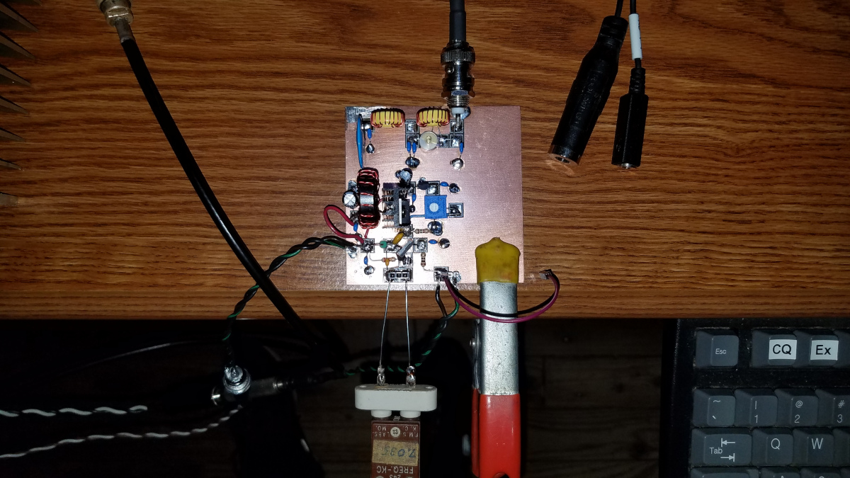
My friend Tom, KN4RRQ had built a two transistor transmittter following a design by VK3YE but was having problems getting good power out of it. It was supposed to do about five watts on 12 volts and 20 watts on 30 volts, but it wasn’t. It uses a BD139 transistor oscillator followed by a IRF510 or IRF530 amplifier. Tom sent me a few BD139s since I didn’t have any and I threw one together to see what I could get it to do. I had the same problem with very low output (about half a watt) until I added a bias circuit which brought it close to five watts. Harmonic levels were too high for my liking with the original low pass filter so I made the second stage of that filter a 20 meter trap which got that under control. Modifying the filter must have changed the load seen by the FET. Output was up to 8 watts operating on 12.5 volts! I put it on the air, using my FT-2000 to receive and my CQ was answered by Wolf, IN3TWX. I knew him from my 2 meter EME days so that was fun! Wolf gave me a 578 report with this little rig. It does have a bit of chirp.
The 8W20W transmitter as set up for the IN3TWX QSO
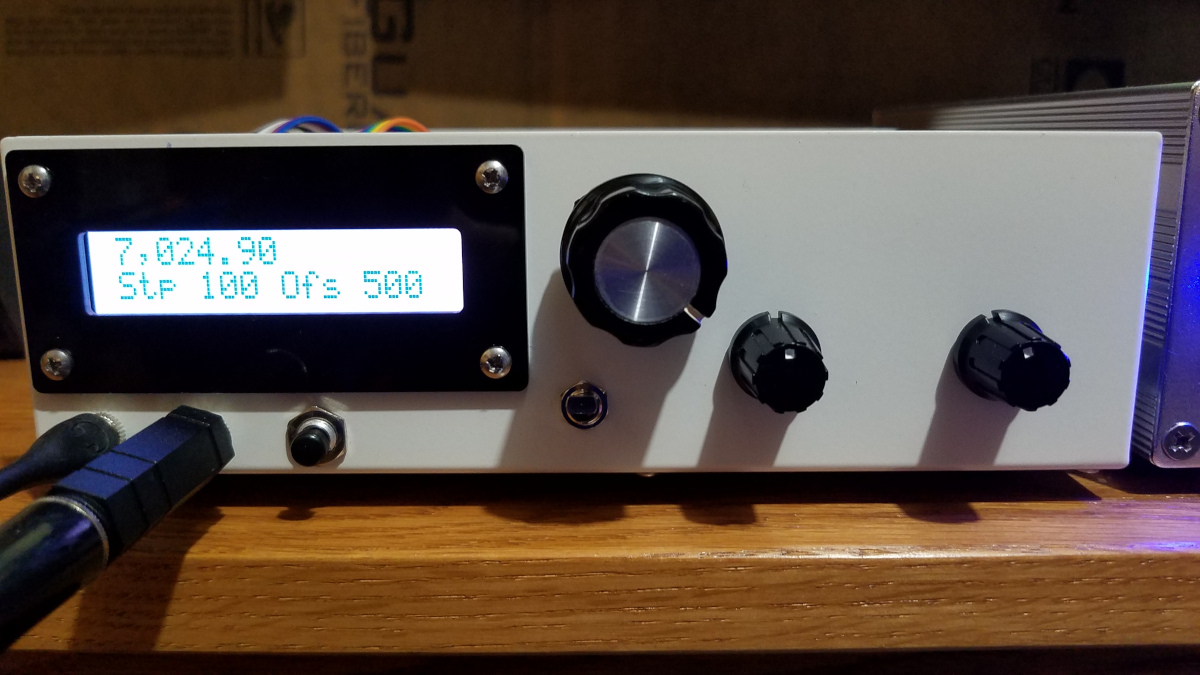
I was still looking for a QRP transceiver with frequency agility. I was able to save a few pennies and buy a DC40B transceiver kit and audio filter kit from Pacific Antenna. It put out a little over two watts when operated at 12.5 volts on a battery. I built a synthesized VFO using an Arduino nano and Si5351A synthesizer module. I started with a design by W3PM from QEX July/August 2015 and made a few minor changes. I added a low pass filter and post-amp to bring the level up enough to drive the DC40B. I had a few trials getting the VFO to properly drive the rig but eventually got it working well. Describing the rig in detail is not the focus of this post.
On the morning of July 29 I was calling CQ with the DC40BV (my nomenclature for the DC40B with VFO) on 7021.5 kHz when I heard the CY0S Sable Island DXpedition begin calling CQ on 7023 listening up (working split frequency). I was able to hear them because the filtering on this little rig is OK but surly not great. I wondered if I could manage to work them with this little rig? The receiver is direct conversion. I have it configured for a positive transmit offset since I normally prefer to listen on the low side of zero beat but of course being a D-C receiver it works equally well on the upper side of zero beat. If I tuned up to 7024 or so I would be able to hear CY0S and be transmitting one kilohertz or so above them, in about the right place for their split since they had just started up and there was no pileup. I hastily dialed up, actually going a bit higher than that but I could still hear them due to the somewhat wide audio filter. My first call went unanswered and they called CQ again, but my second call got them! I worked CY0S with a 2 watt kit/homebrew transceiver with direct conversion receiver! If there had been a pileup the QRM would have killed my ability to hear CY0S since I would be listening right in the middle of it, but I was in the right place at the right time when they had just started up and had very few callers. A 400 mile QSO is no great feat but it was fun working a semi-rare DXCC entity with such a simple and unlikely setup!
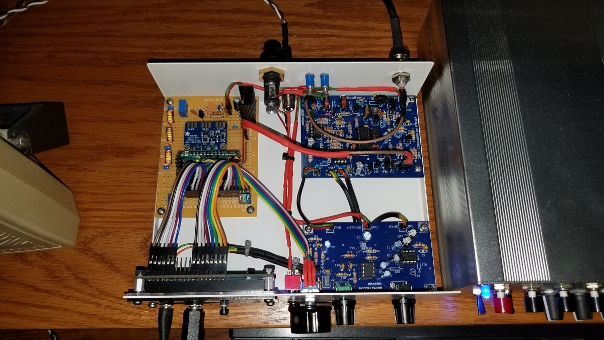
The DC40BV immediately after my CY0S QSOInside view of the DC40BV rig. I am still making a few minor changes and have some more tweaking of the VFO code and capabilities to do.
I was already thinking about having the ability to toggle the receive-transmit offset to plus or minus 500 Hz (my preferred pitch for listening to CW) because with a direct conversion receiver listening on the opposite side of zero beat can be helpful in avoiding QRM. But this QSO got me thinking. Perhaps I will try to make the offset completely variable, so I can go either side of zero beat and even have fully configurable split frequency capability. That will test my limited Arduino coding capabilities, but I think I can get it done with some trial and error.
I have a passion for radio, but it goes deeper than a hobby for me. As I continually struggle to maintain my relative independence amid the challenges of some very frustrating and debilitating challenges, it is a survival tool. To that end it is important enough to be among the highest priorities in life. Thus when misfortune struck I put much on the line to recover.
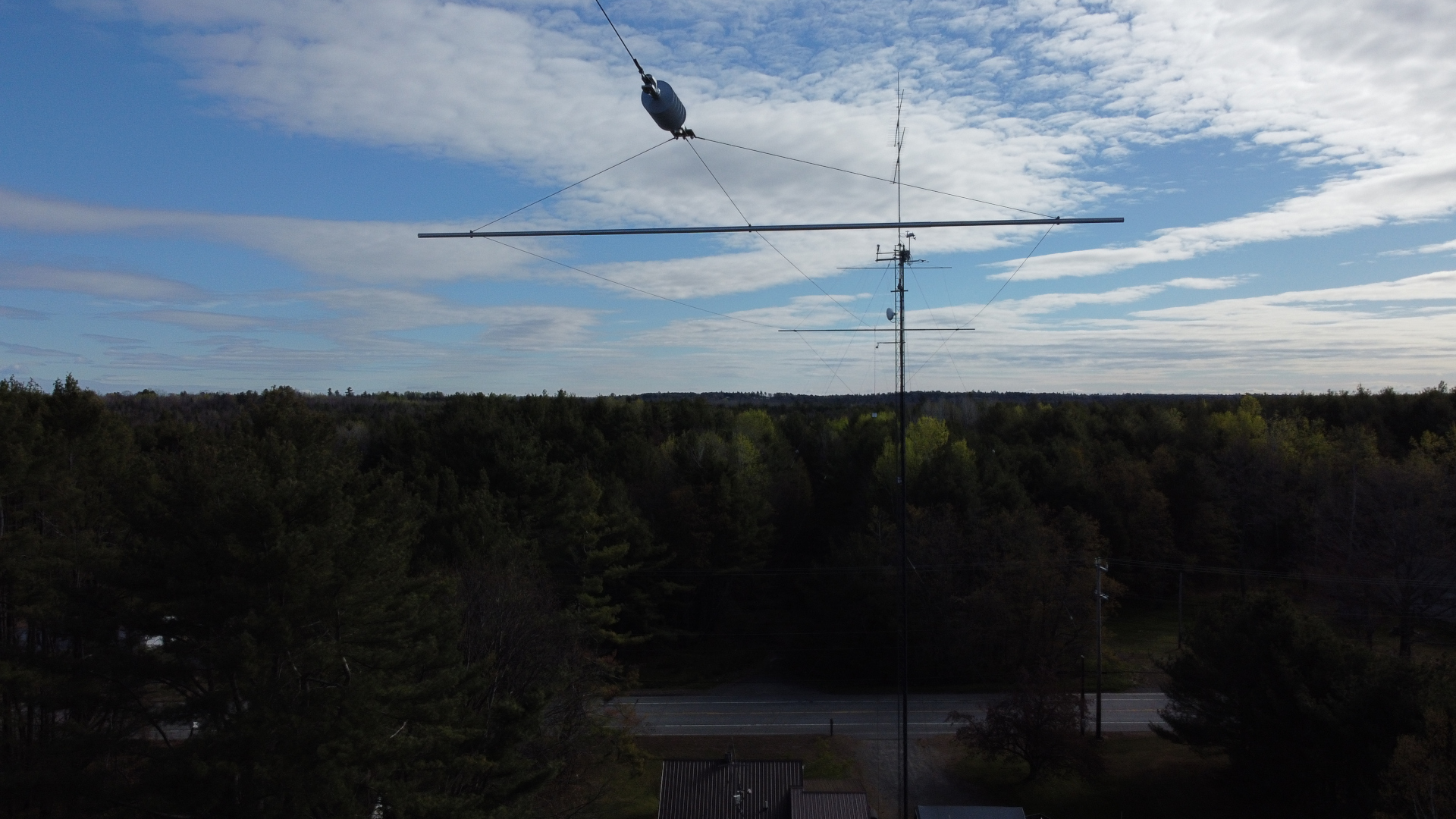
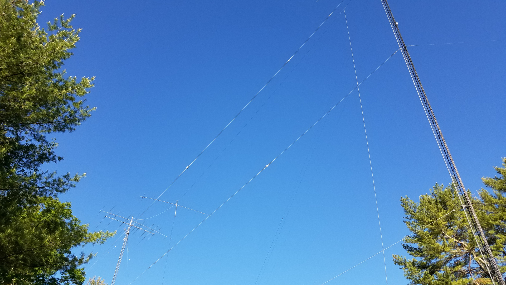
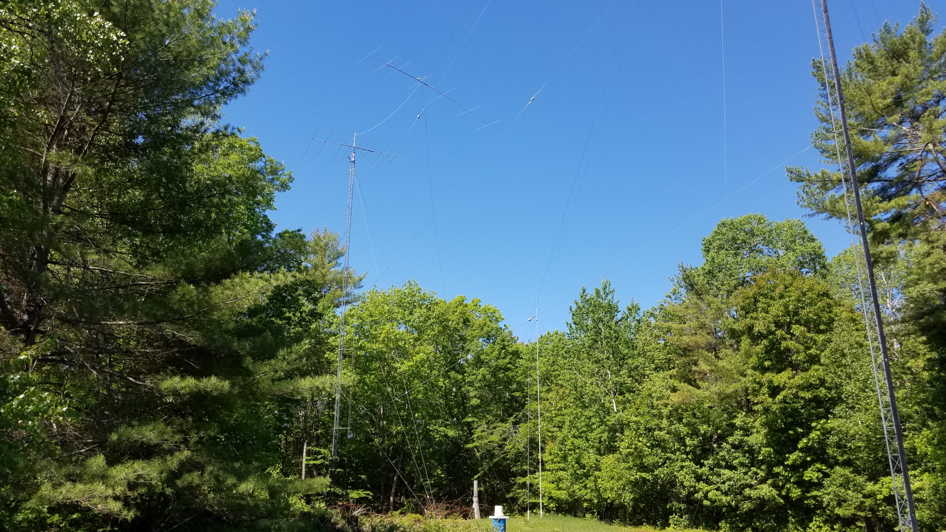
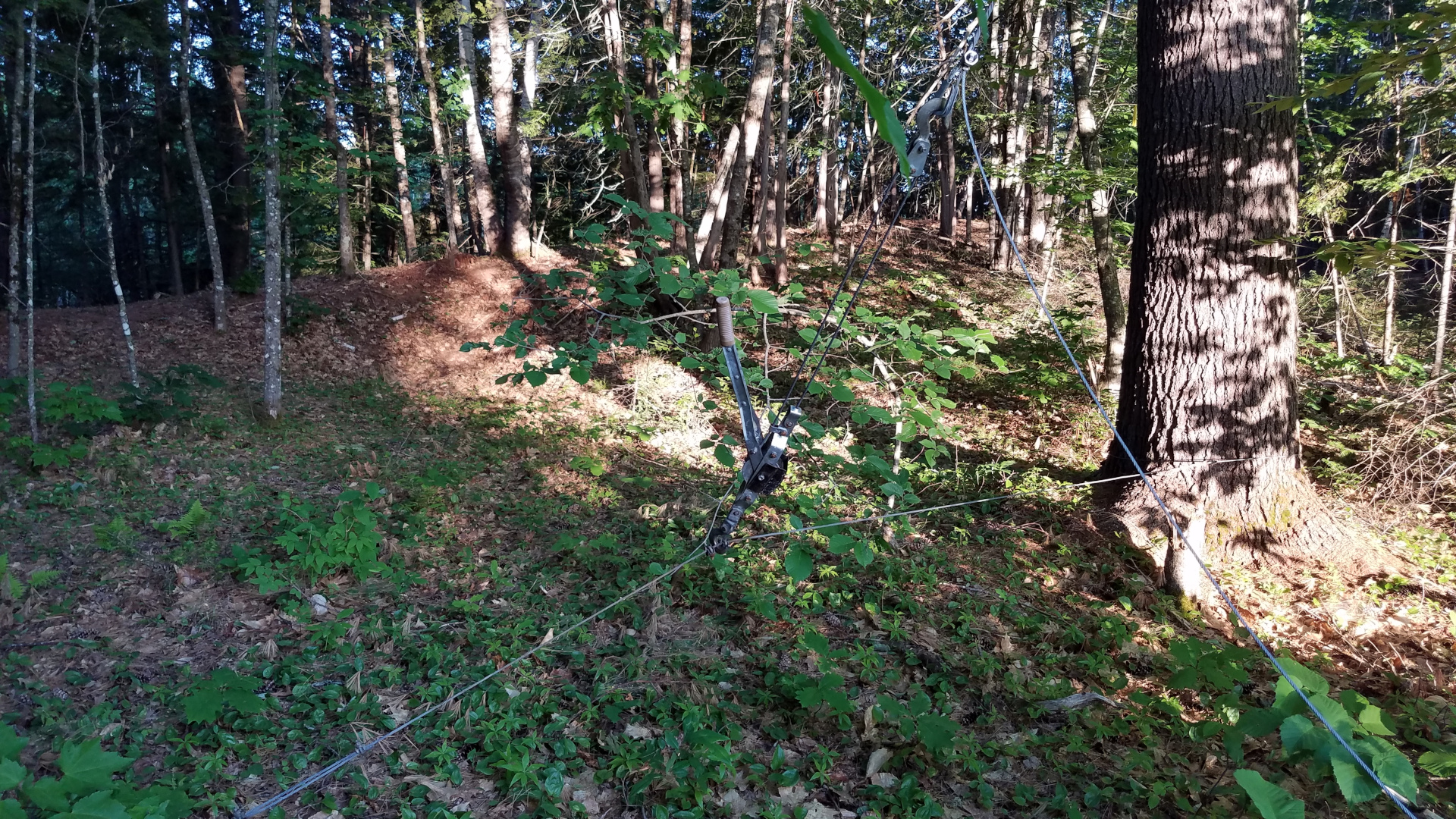
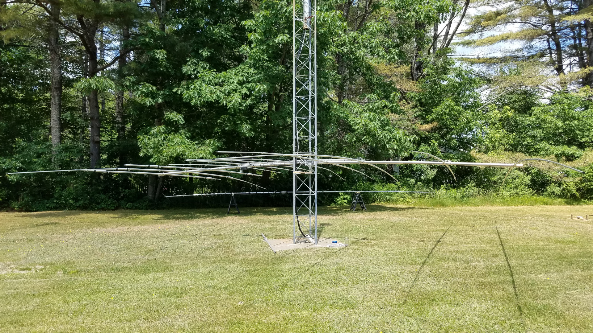
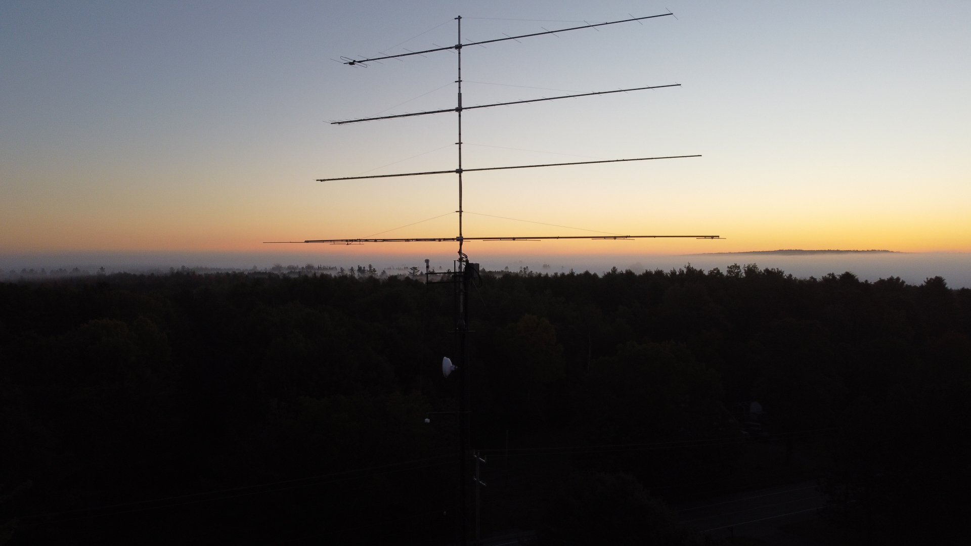
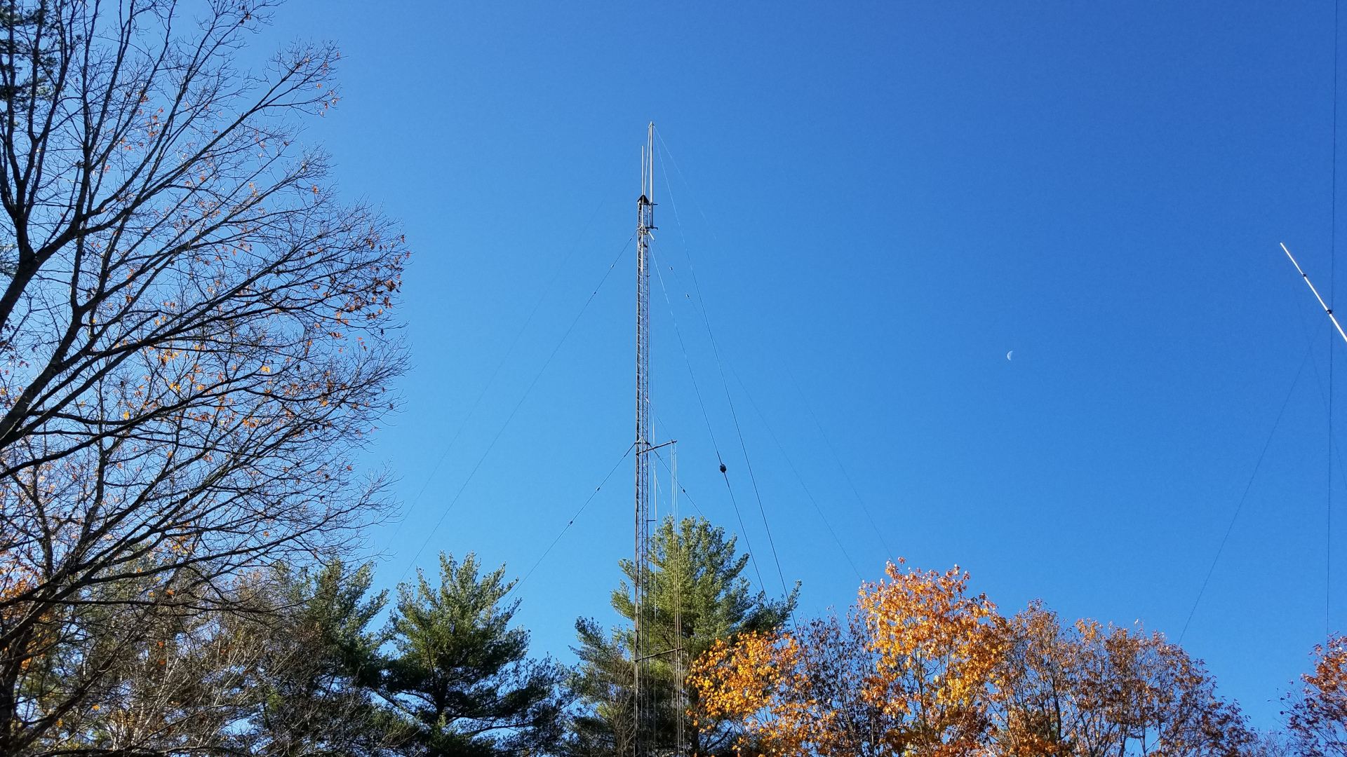
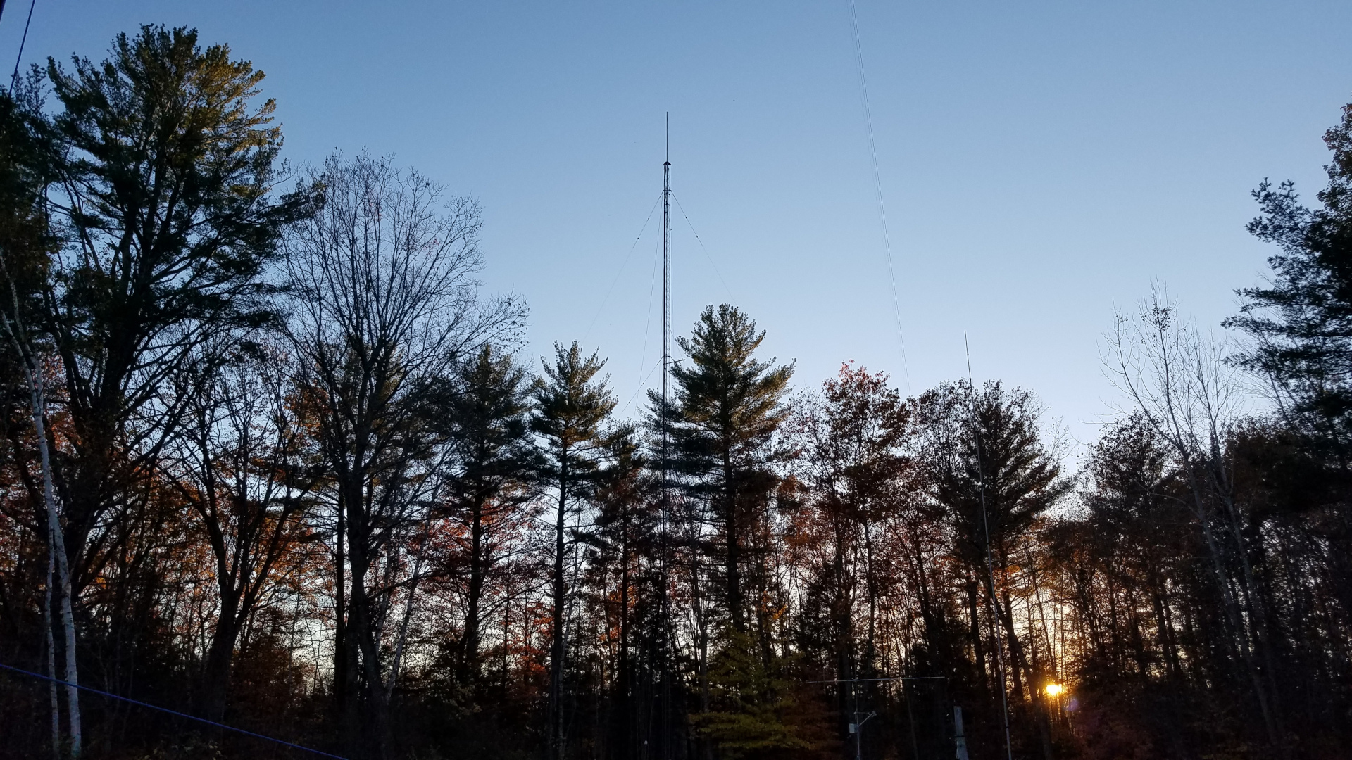
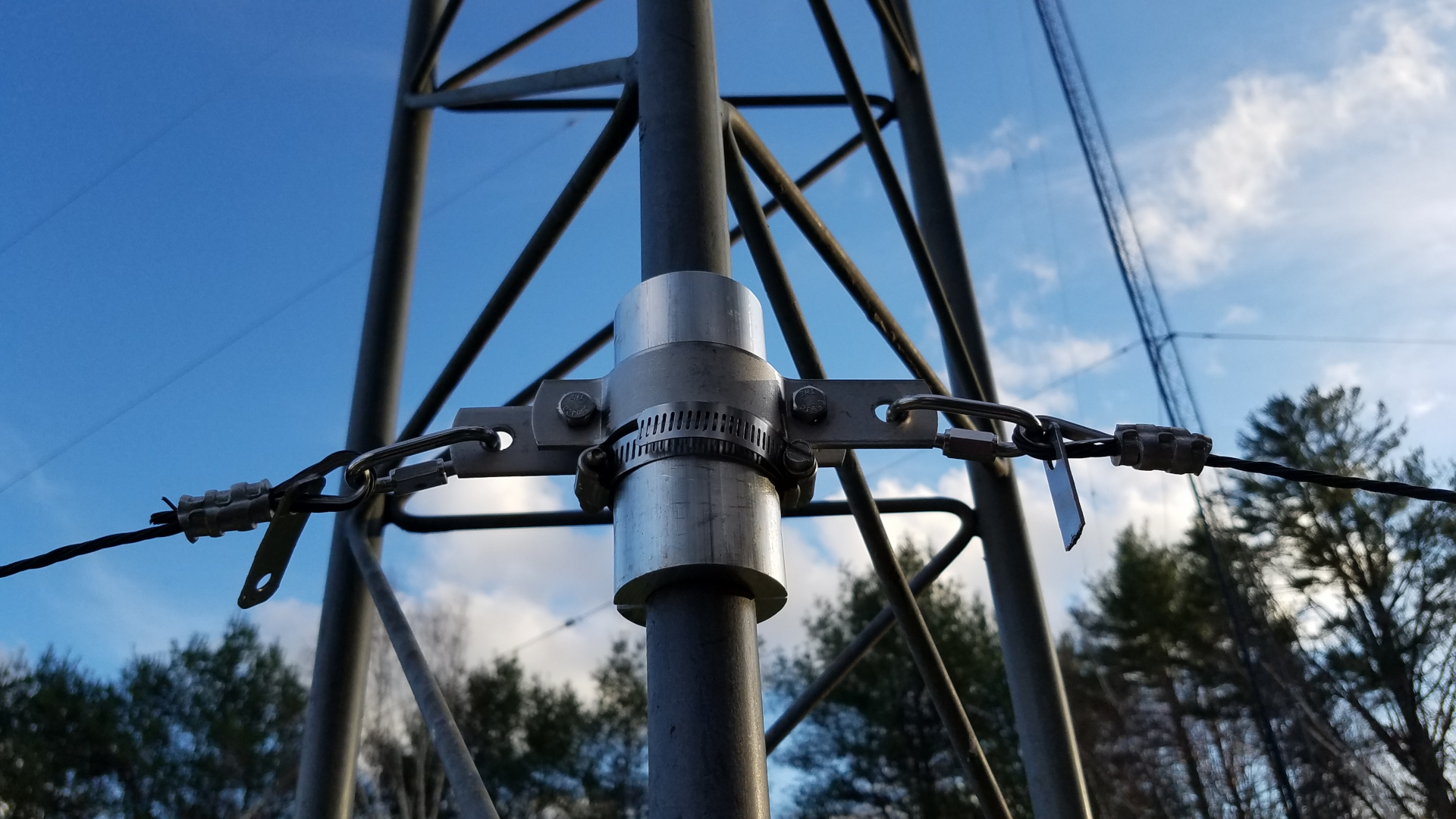
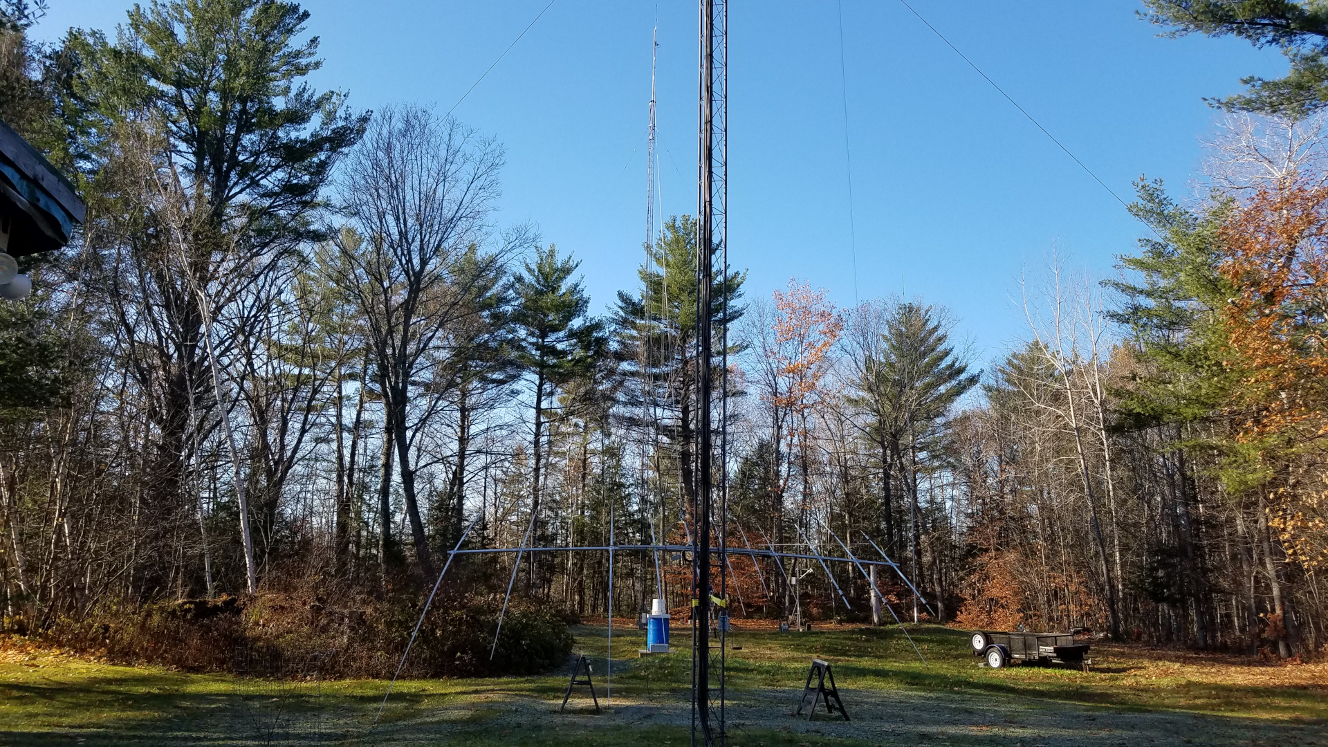
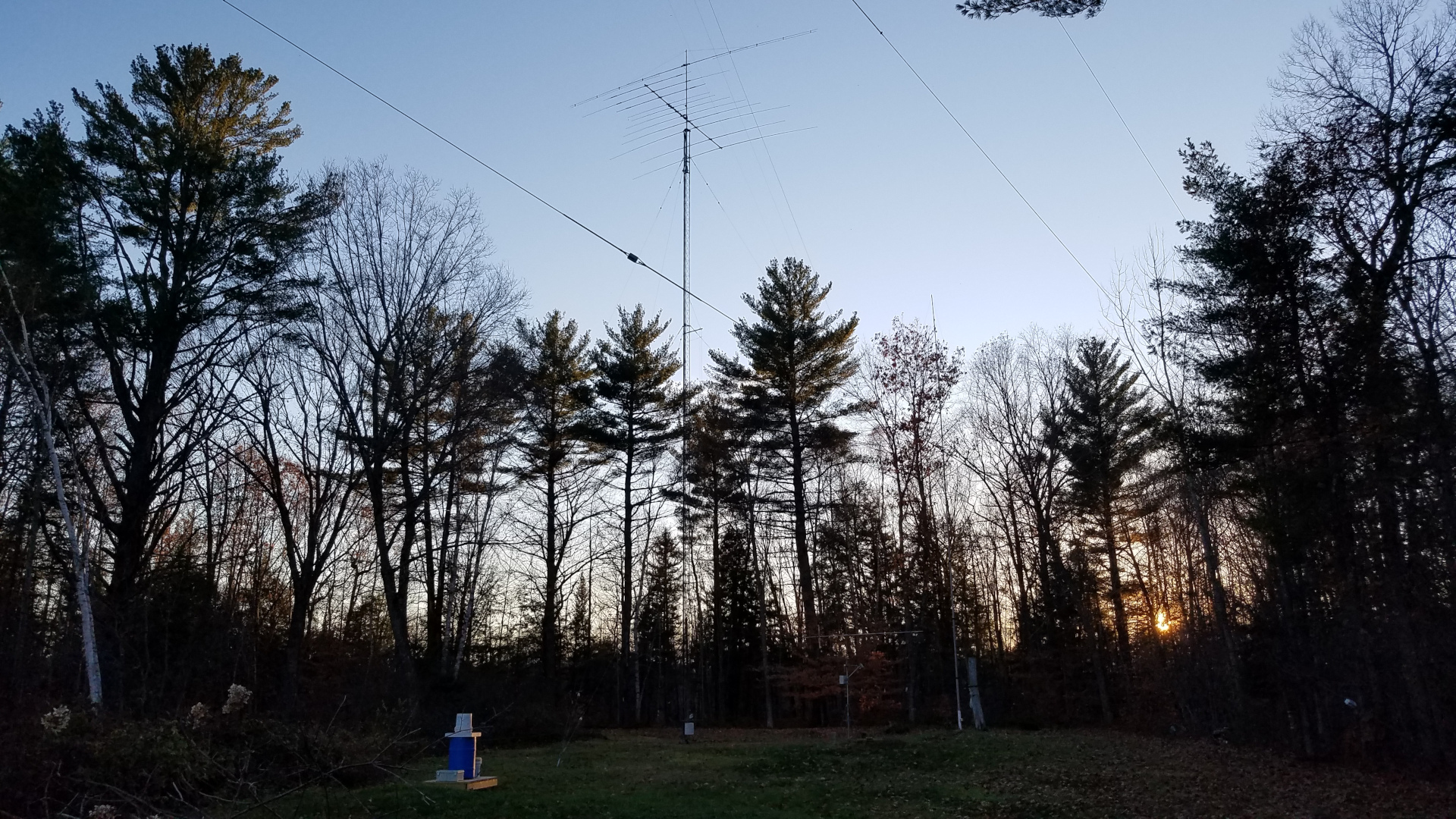
Over the past several years, with sacrifices on my part combined with generous contributions from fellow hams I have been on a station building spree. I got back into VHF/UHF weak signal work, greatly improved my HF antennas, and for some time was heavily into experimenting and attempting to work DX on 2200 meters. Things were going very well but all of that changed one winter night in December, 2020. We had a wet, sticky snowstorm that night. All of my wire and yagi antennas were heavily burdened with snow. At some point the strain was too much for the 2200m T antenna that was suspended between my two 100 foot Rohn 25 towers. It broke at one end and fell. The sudden reduction in side loads on the towers caused them to move slightly. With the burden of extreme weight of the snow, this caused significant, but fortunately not catastrophic damage. Some yagi elements were bent, traps damaged, coax cables damaged, masts bent just enough to bind, and one Rohn 25 top section was bent slightly, causing rotation to be extremely impaired on that one. All of the antennas from both towers were going to have to come down for repairs to themselves and the towers.
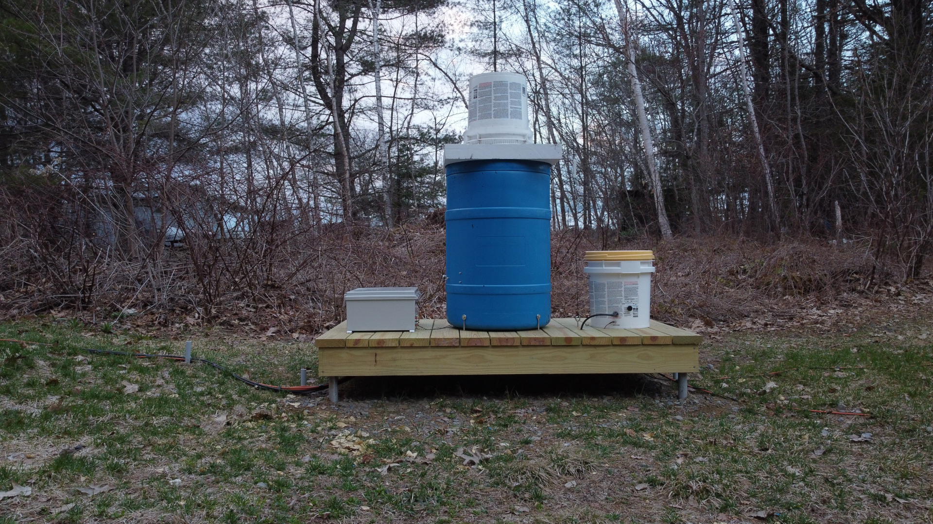
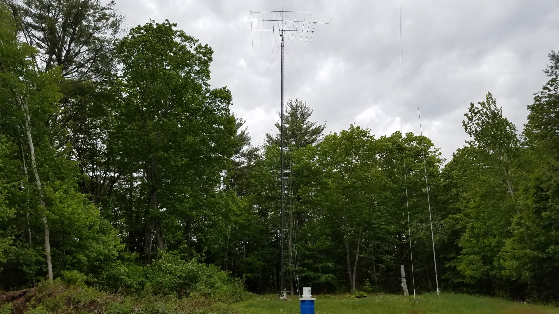
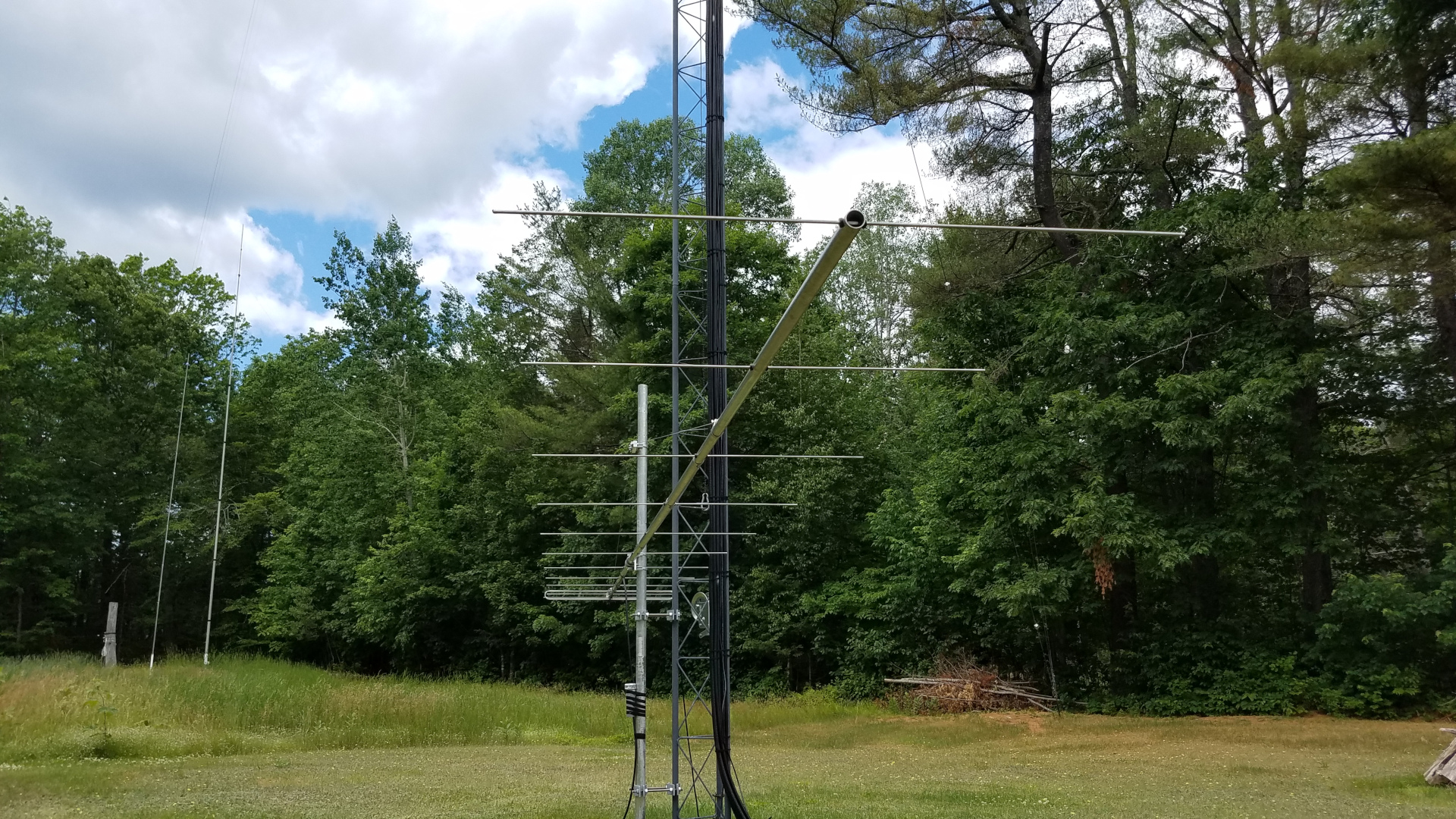
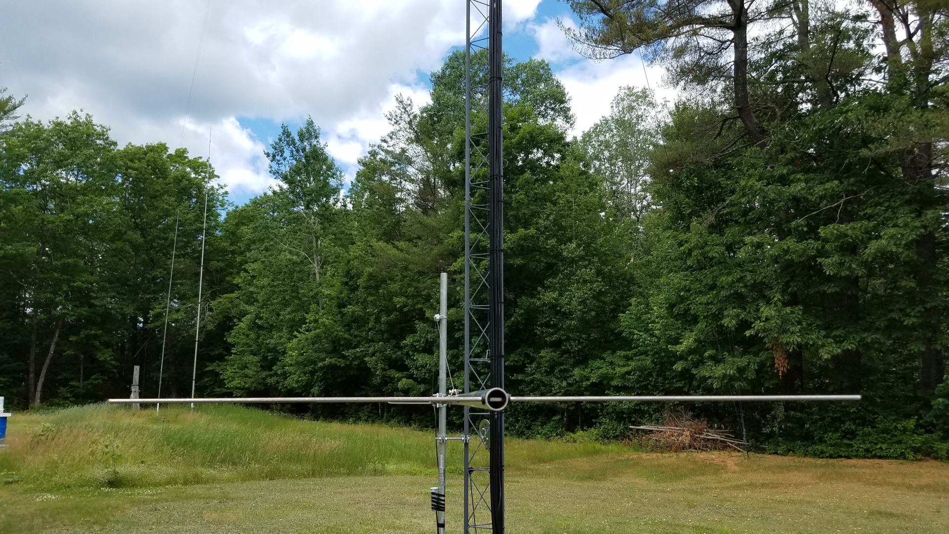
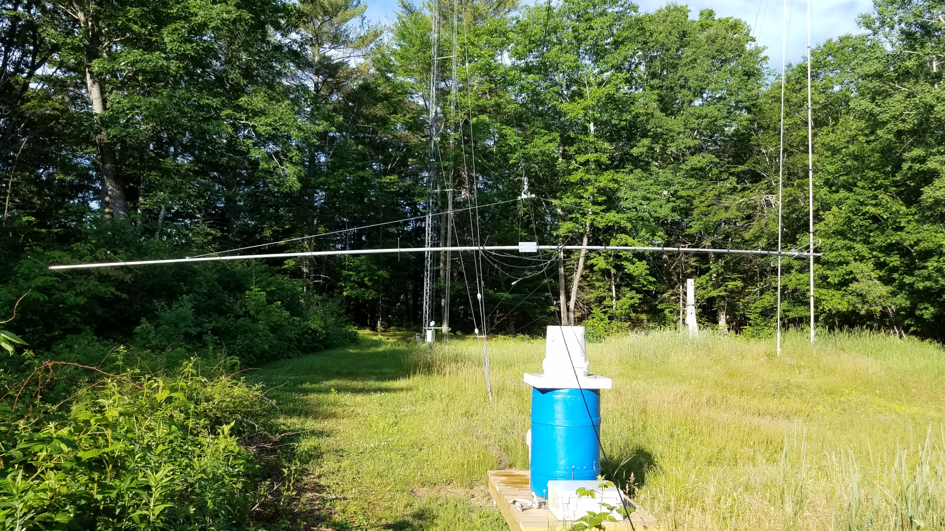
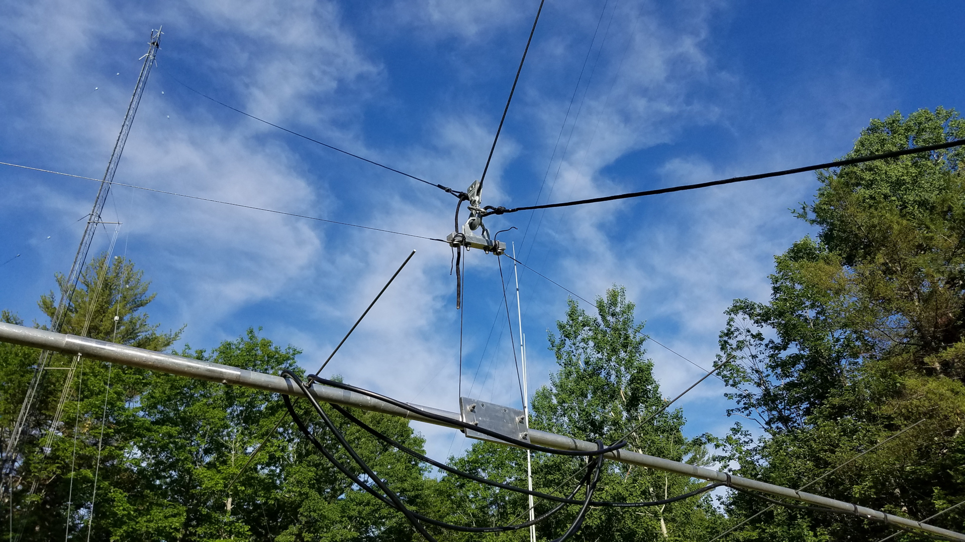
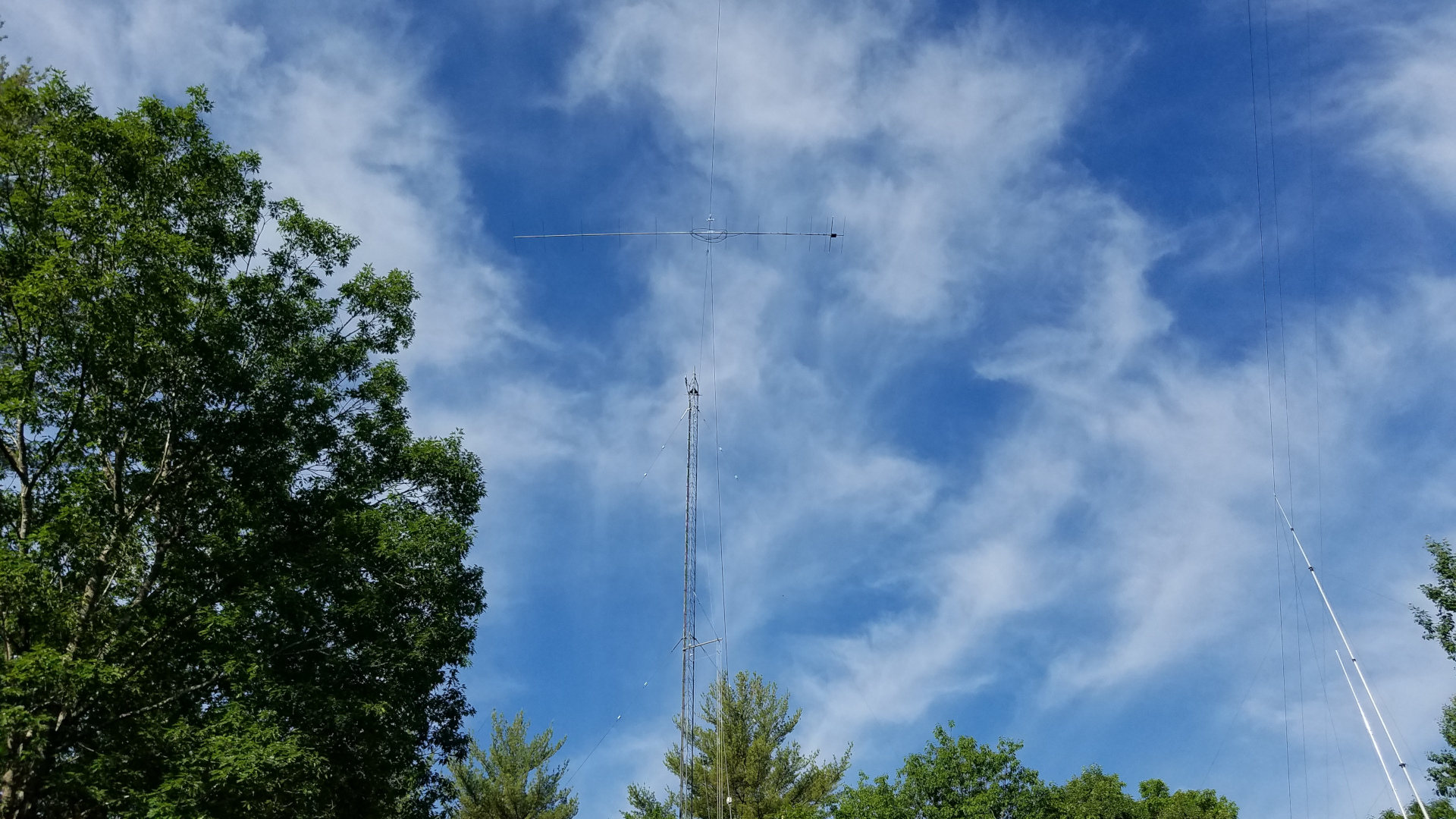
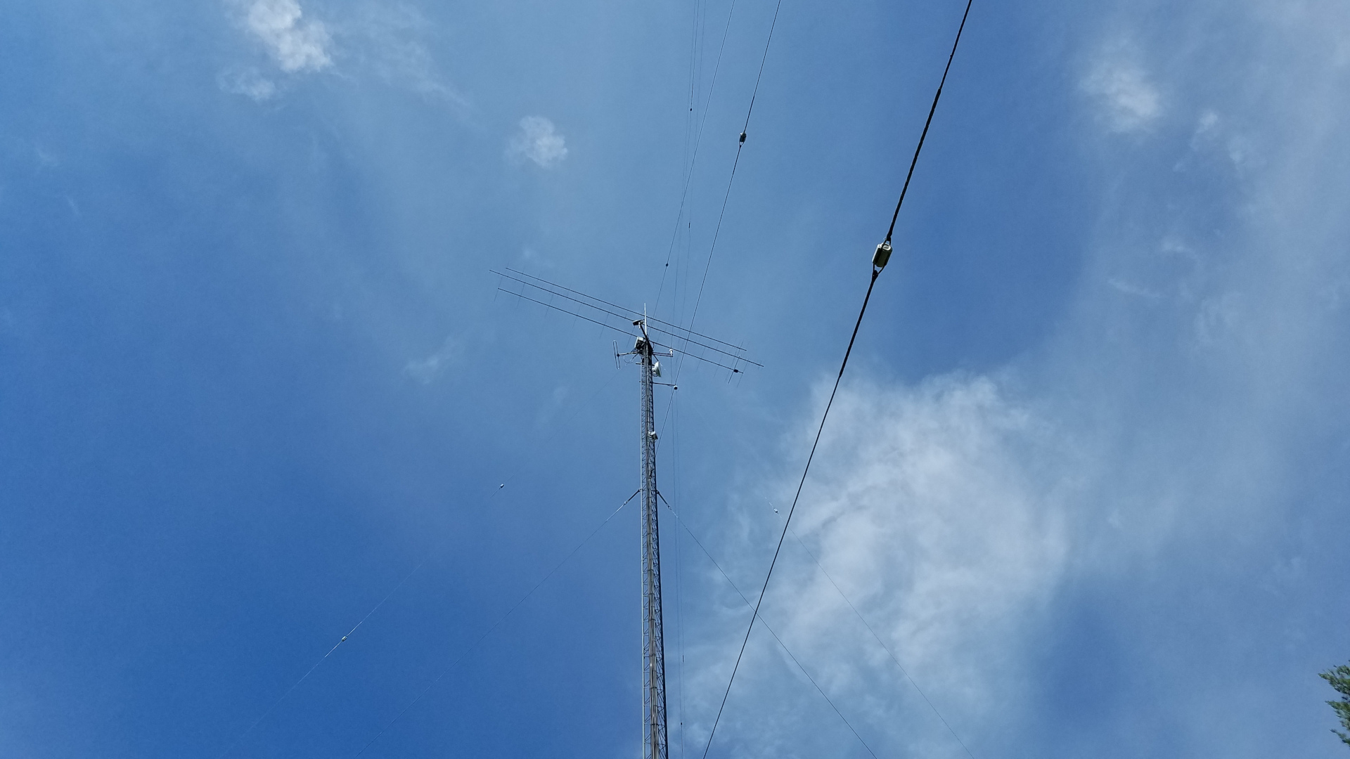
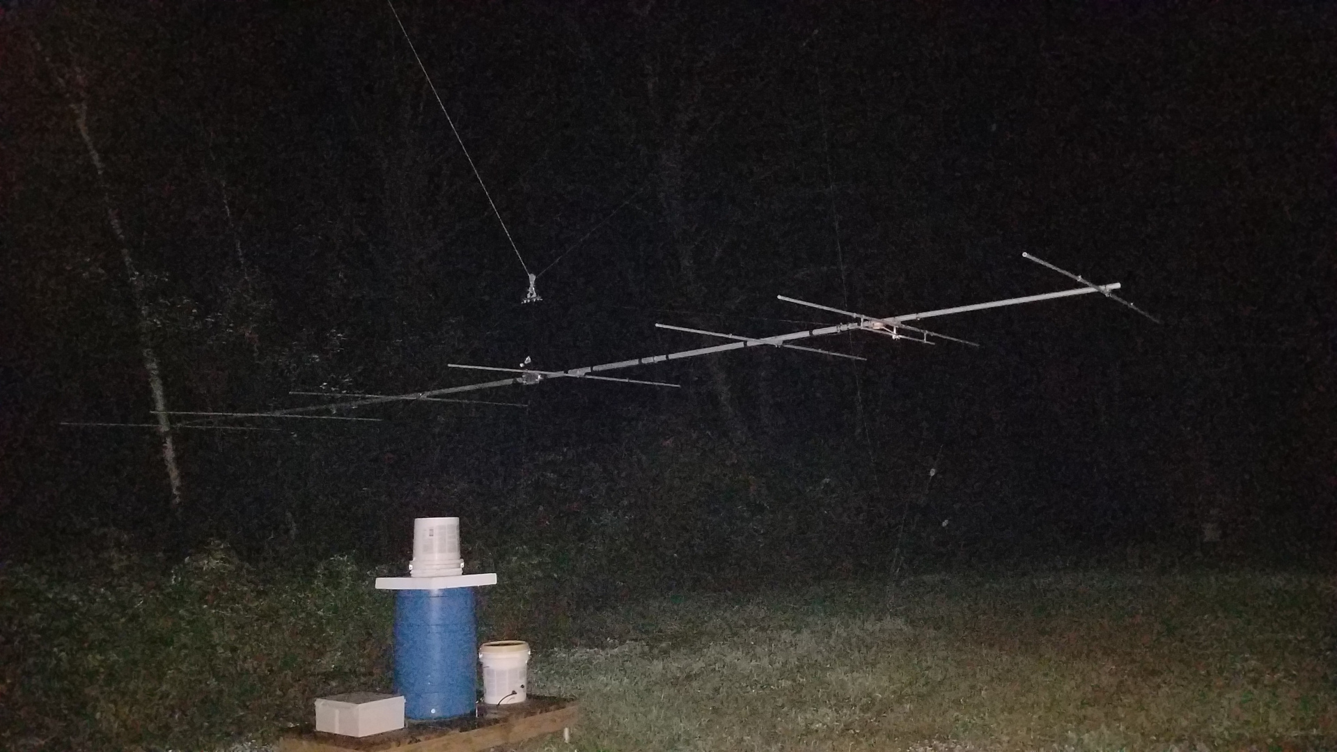
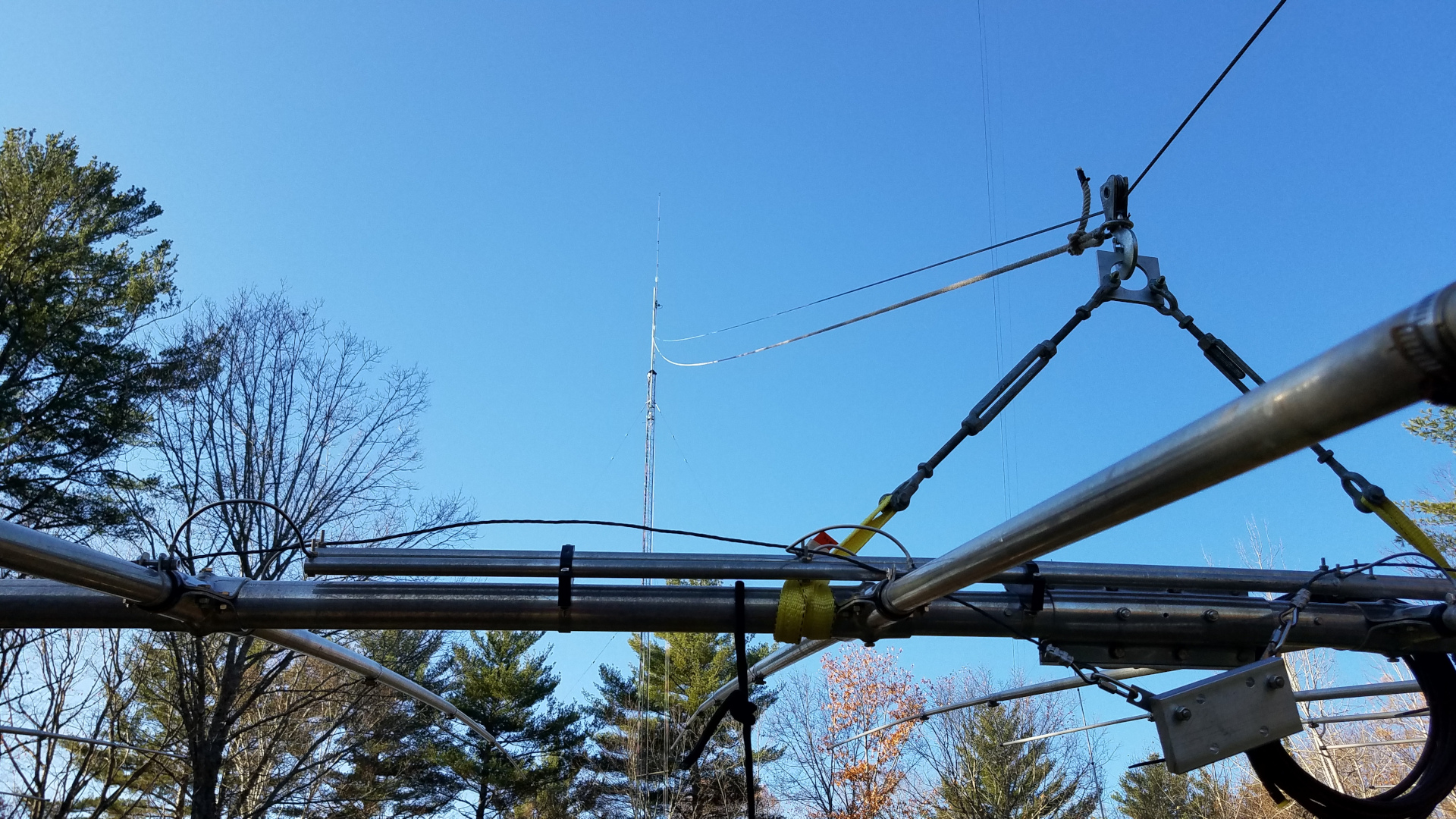
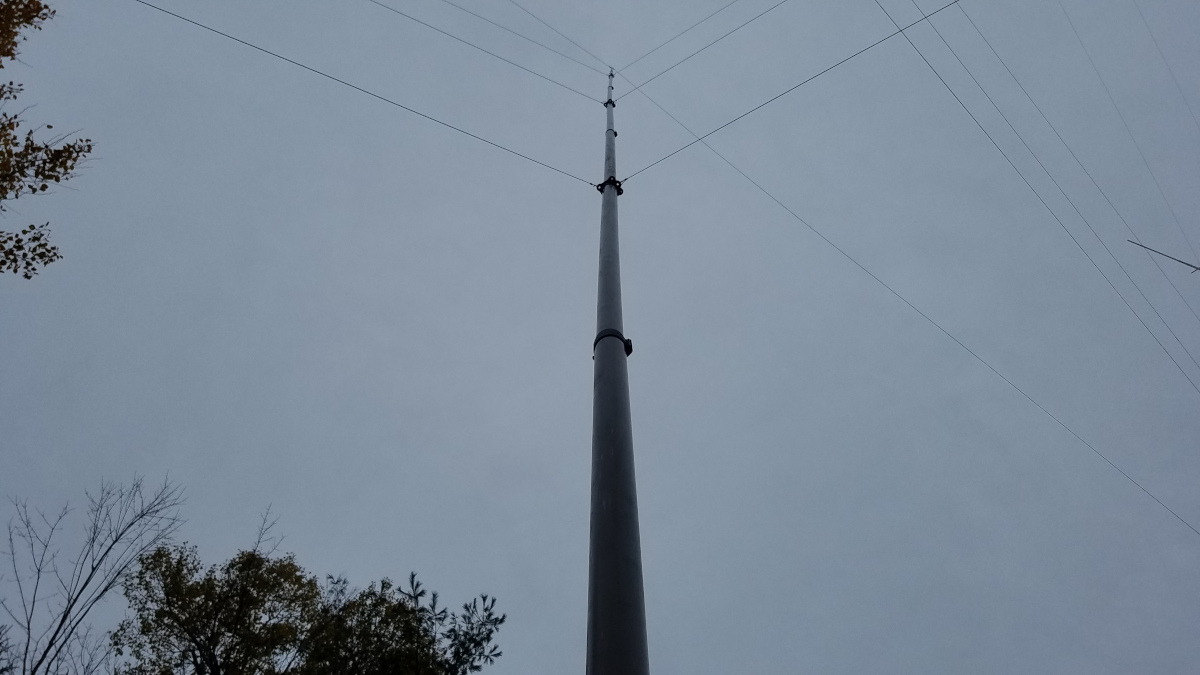
Side view of the 2200m antenna before the incident. It is strung from a point 103 feet up a tower on the right, and 95 feet up the tower on the left. That three wire top hat can accumulate a tremendous snow load under the right conditions.Another view of the 2200m top hat, taken from one of the towers. Failure occurred when the antenna broke free of an insulator at one end.Base and coil platform for the 2200m antenna. There is matching transformer and tap selection relays in the box at the left, a 2.2 millihenry coil/variometer in the blue drum, and a smaller version of same for occasional use on 630m in the bucket at the right.
There are no photos of the aftermath or 2200m antenna laying in the snow. I was too depressed that morning to want to document anything. I stabilized what I could and over the next several days foolishly repaired the 2200m antenna. That allowed me to continue LF operations until Spring but I knew those days were coming to an end. Assuming I was able to repair the towers and other antennas, I could never again risk a similar disaster.
The first challenge was how to finance repairs. If I chipped away at it with whatever I could manage to set aside from my income, recovery would take years. The other option was to see if I could get a loan, despite my fixed income falling below lender minimum guidelines. I was not doing so well since the loss of most radio activities. Under some gentle prompting from my health support team I decided to pursue a loan. Fate smiled upon me and I got the loan, a sum not less than a third of my annual income. It will take some time to pay that off but I was on my way to rebuilding!
It was going to be a big project for me. I do all antenna work alone. That means a lot of trips up and down the towers, as I have no one on the ground to do anything and must often make several trips up for simple tasks. There were complicating factors going into this. One was that several months earlier we lost a local ham and professional tower worker whom I had known for 40 years. He died in a fall from a tower. To be honest that really shook me up and I had some difficulty with climbing early on in this project because of it. I was at least 40 pounds overweight which compounds that darn gravity thing! But I was going to rebuild or perish in the attempt! Lastly there are always days that I am unable to work or be outside, and that has been greatly compounded by a neighborhood situation which has had several of us making complaints. It was very difficult this year to find times that I could do anything at all. I often started around 2:00 AM and finished work shortly after dawn. These same factors make it impossible to schedule work sessions even when volunteers might be available. Under current conditions I either do antenna work alone or it won’t happen at all. I don’t know how many years I will be able to continue this, so I am making the most of it while I can!
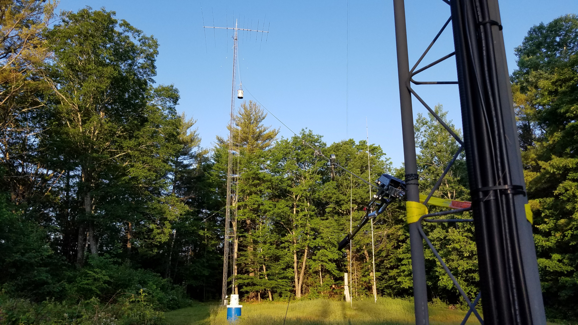
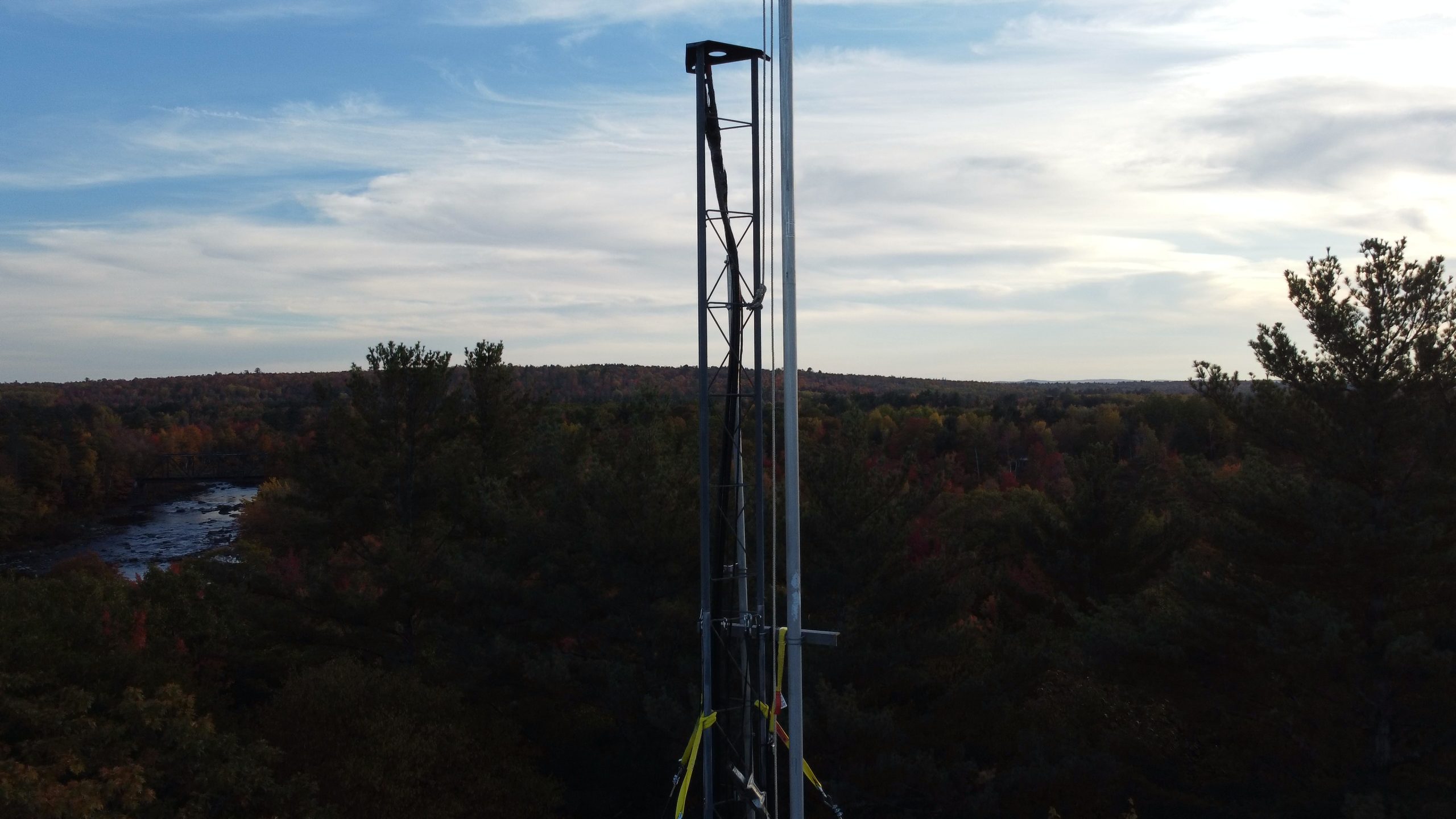
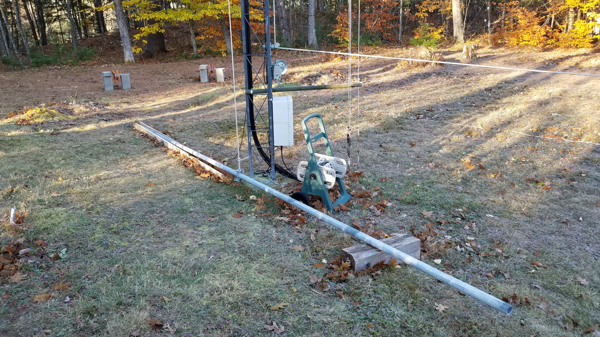
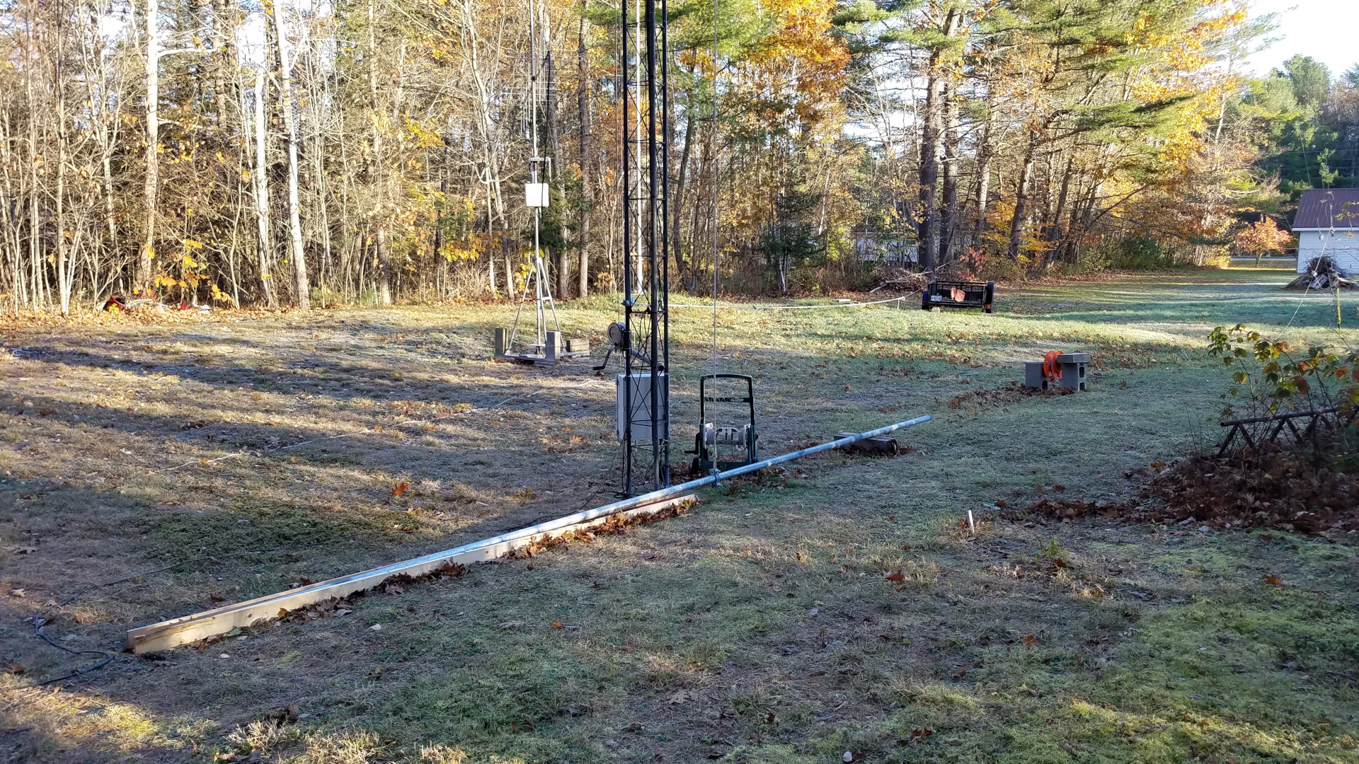
First there were preparations and getting antennas down from the more heavily damaged tower. The 2200m antenna was taken down for the final time, a very sad day since that extremely challenging band had been of great benefit to me. I miss it every day. Some trees that had rather quickly grown up along the path of my tram line were cut, and the tram line was hauled up into place.
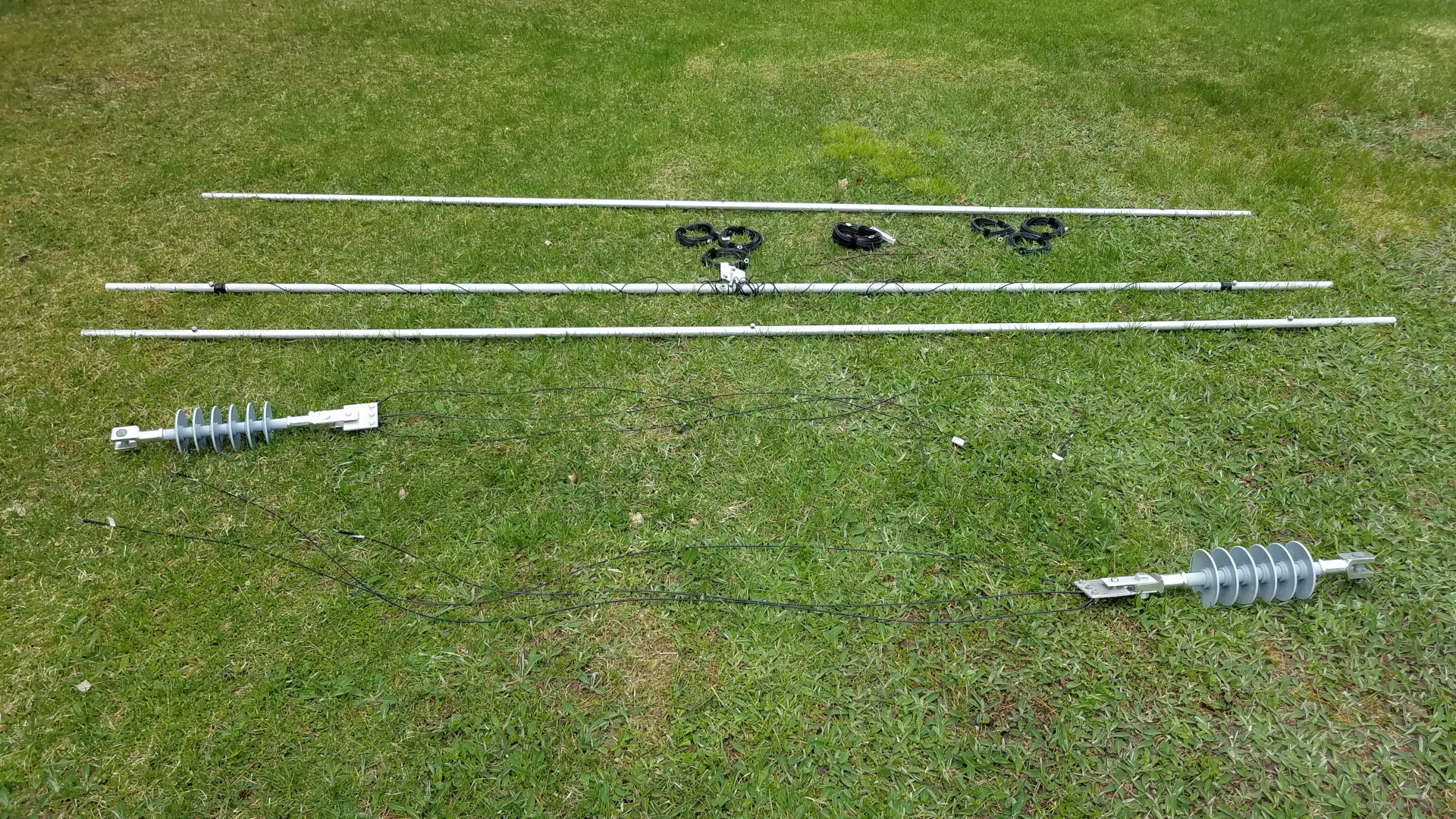
The 2200m antenna doesn’t look like much after disassembly! Some coils of wire, three 12 foot aluminum spreaders, and some big honking insulators.These antennas had to come down, even though things don’t look too bad in this photo. Traps on the TH11DX had broken (shattered!) plastic end caps and were weak and wobbly, some element tips were slightly bent and the boom truss was in danger of failing. Coax had issues on the 6 and 2 meter antennas, boom truss on 2m had partially failed, some 6 meter elements rotated out of plane, and the mast was severely binding in the tower top due to slight bending of both the mast and the tower top section.Trees have been removed from the area on the left to provide space for tramming.Ropes and cables for tramming operations. One wire rope is the tram line, the other is a backstay to prevent failure of the mast from the stress of tramming the heavy TH11DX.The mast backstay attached to a rope and ready to be pulled up.
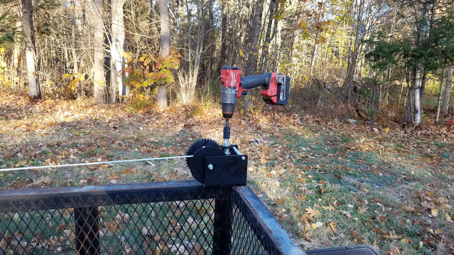
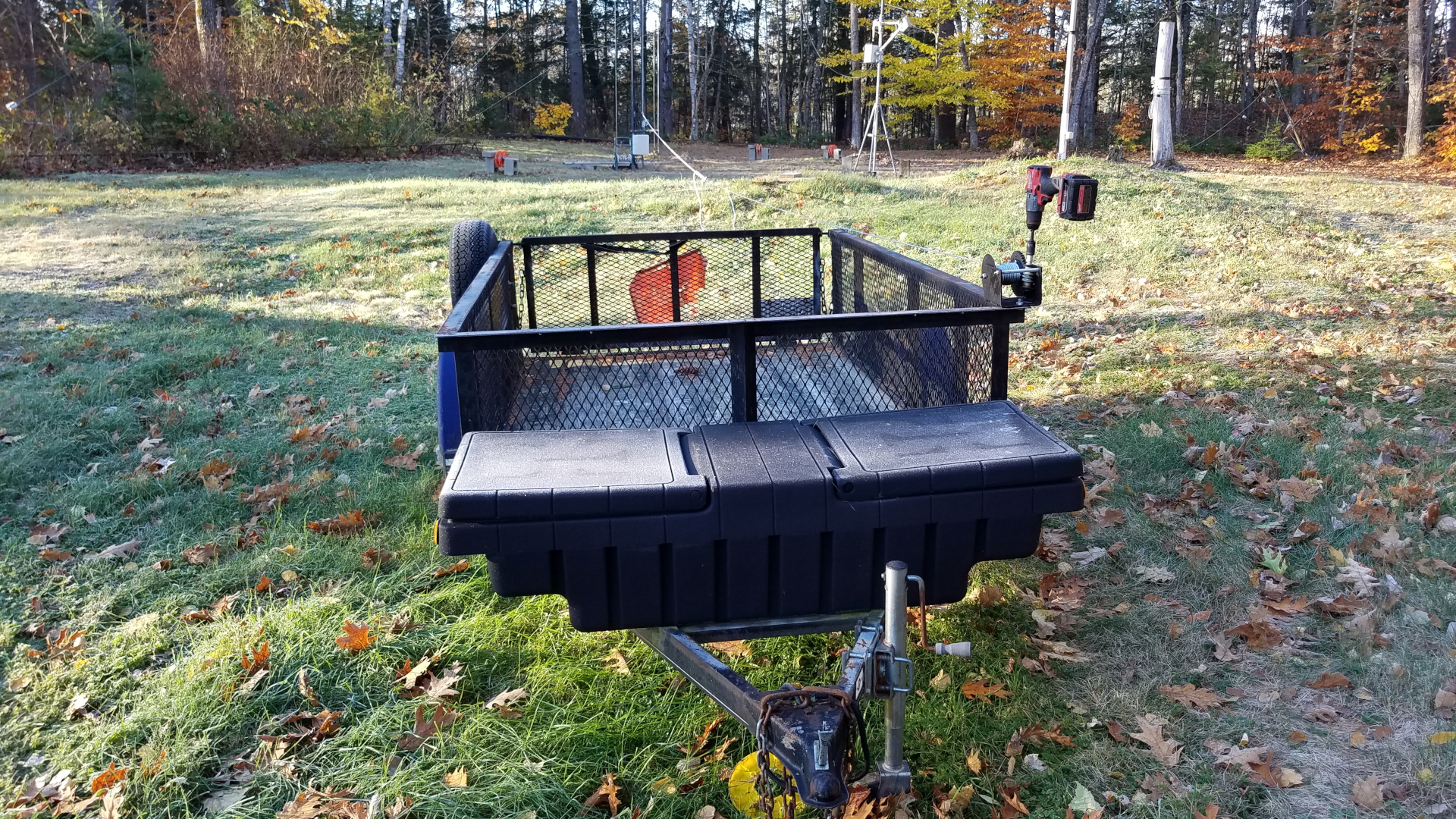
Special tramming operations needed to be carried out for the 6 and 2 meter antennas in order to get them past the elements of the TH11DX. It might have made more sense to remove the TH11DX first, but this was early in the season when I was very nervous climbing. To be honest, this was a mind game. I needed to see the big expanse of the TH11DX below my feet as I stood on a mast step to reach the upper antennas, or I would never get myself up there! I will argue that one should not climb if experiencing such discomfort and having to play such mind games but this was do or die for me. I was willing to take the risk of pushing myself into uncomfortable situations. In order to solve this clearance problem, the tram line was run horizontally from the mast over to the top of the other tower where it was joined to a rope running through a pulley down to a hand winch at the base of the tower. This allowed the VHF antennas to leave the tower going out horizontally, then to be lowered to the ground by letting out rope from the winch.
The 2 meter antenna suspended on the high, mainly horizontal tram line.Tram line being lowered with the 2m antenna hanging in the middle.The 2m antenna nearing ground level.6m antenna out on the high tram line.Tram line being lowered with the 6m antenna on it.Since I was still about 40 pounds overweight at this stage, I took advantage of the tram line to bring up my bucket of tools… less gravity pulling at me than if I climbed with it attached to my climbing harness.
With the smaller antennas down it was time to tackle the TH11DX. For this, the tram was rigged in a somewhat more conventional manner, now going from the top of the mast down to a few feet above ground on the other tower. After the nearly 100 pound antenna was at ground level, I learned that I need to eat more Wheaties or something! It was a struggle to pick it up, walk over to the short Rohn 45 tower with it, and mount it at shoulder level on that tower where it would remain until everything was ready for it to go back up.
The backstay tension system. This is critical when tramming nearly 100 pounds of antenna with a tram line attached to an aluminum mast!TH11DX suspended on the tram line. The tram line and backstay can be seen.TH11DX about half way down the tram line.TH11DX has nearly reached ground level.Tram line has been slacked off by means of the comealong by which the tram is attached to the slings on the tower. That lowered the TH11DX the final bit onto saw horses.The TH11DX moved to a temporary spot for repairs.
I was not doing so well after months of not having radio which I rely on for stress management, and really wanted to be active for sporadic E season and the Perseids meteor shower. I decided to repair and mechanically upgrade the 2m antenna and then temporarily put it on the other tower, below the 222 and 432 MHz antennas.
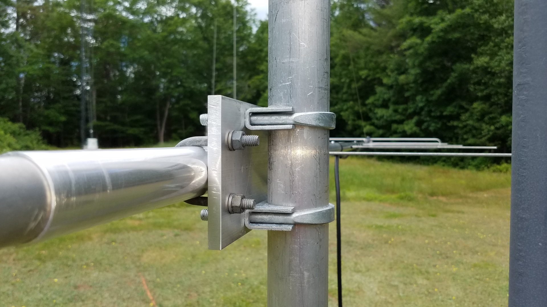
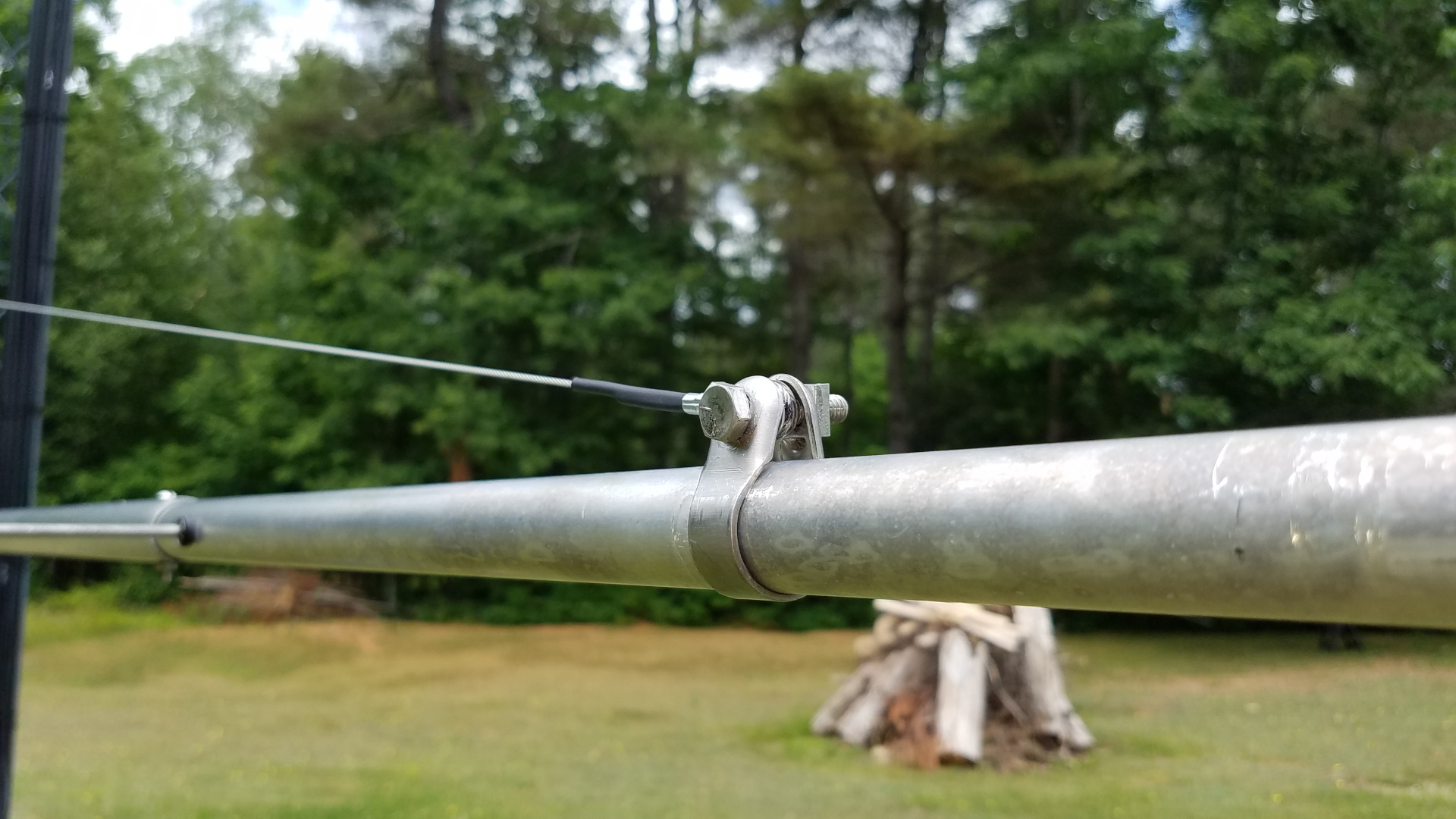
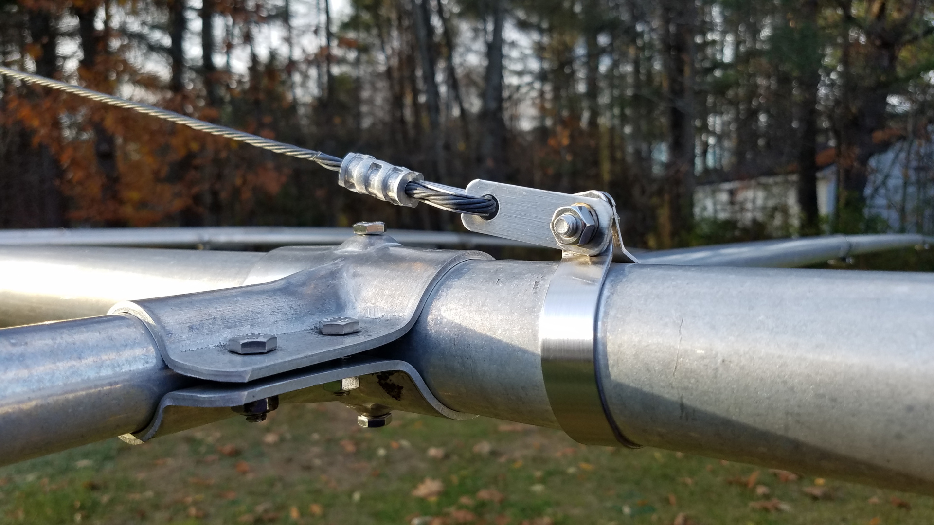
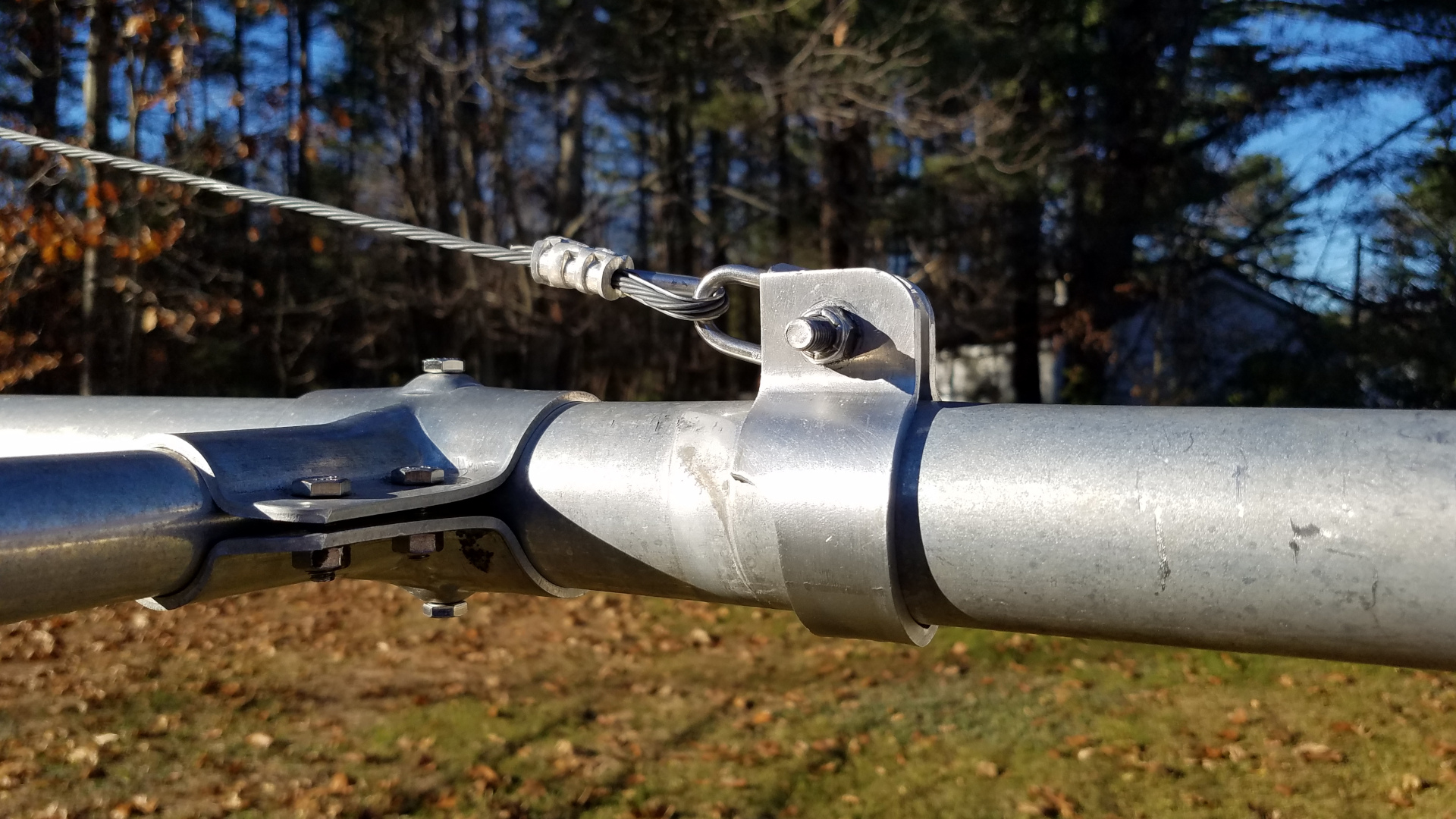
New, upgraded 2m boom to mast clamp. Overkill.New, upgraded 2m truss to mast clamp. Overkill, again.New 2m truss to boom clamp. The truss itself was upgraded from dacron rope (too stretchy!) to stainless wire rope.Refurbished and upgraded 2m antenna.OK, now I am happy with the alignment of elements!2m antenna on the tram line ready to go temporarily to the northeast tower. Rather than lower HF wires out of the way, I opted to use the same high tram running between the tops of the towers, but in the reverse direction (rope, pulley and winch now on the southwest tower).Quick and dirty rigging of antenna to tram line, but it works fine.2m antenna on the raised tram line.2m, 432 and 222 antennas on the northeast tower.
I caught a couple of massive E skip openings on 2 meters and did very well in the Perseids on both 2 meters and 222. I was glad I took this step of putting the 2 meter antenna up in a temporary fashion. After the Perseids it was time to remove all antennas from the northeast tower and get to work on the new VHF/UHF stack there.
The 6m antenna needed two elements rotated back into plane, new boom to mast clamp, new truss to mast clamp, new coax and a rebuild of the center of the T match.All of the antennas down for work. 6 and 2 mounted on the utility trailer, 222 and 432 on saw horses, TH11DX on the short tower. 222 and 432 got new coax, new boom to mast, and new truss to mast.The 2m antenna hanging on the tram line before dawn, ready to go up at first light while there is no wind. It is going up already attached to a 6 foot mast extension.The 2m antenna is up. Photo clipped from a drone video.
I had a setback after getting 2m, 222 and 432 yagis up and mounted on the mast. While raising the mast to final position in preparation for rotator installation and adding the 6m antenna, the three coax cables got caught on the tower and damaged. I had to take all three antennas down and replace the coax a second time!
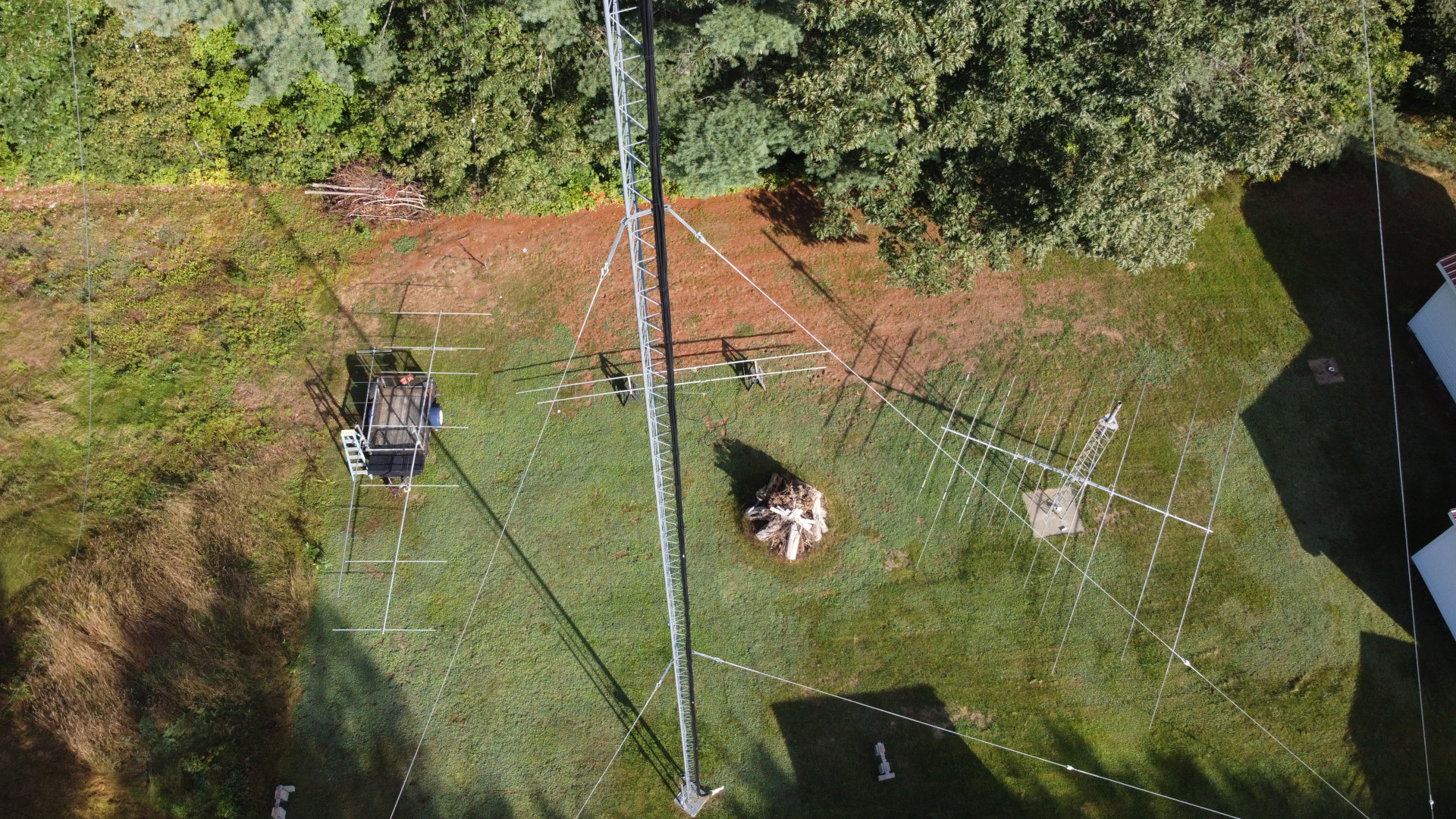
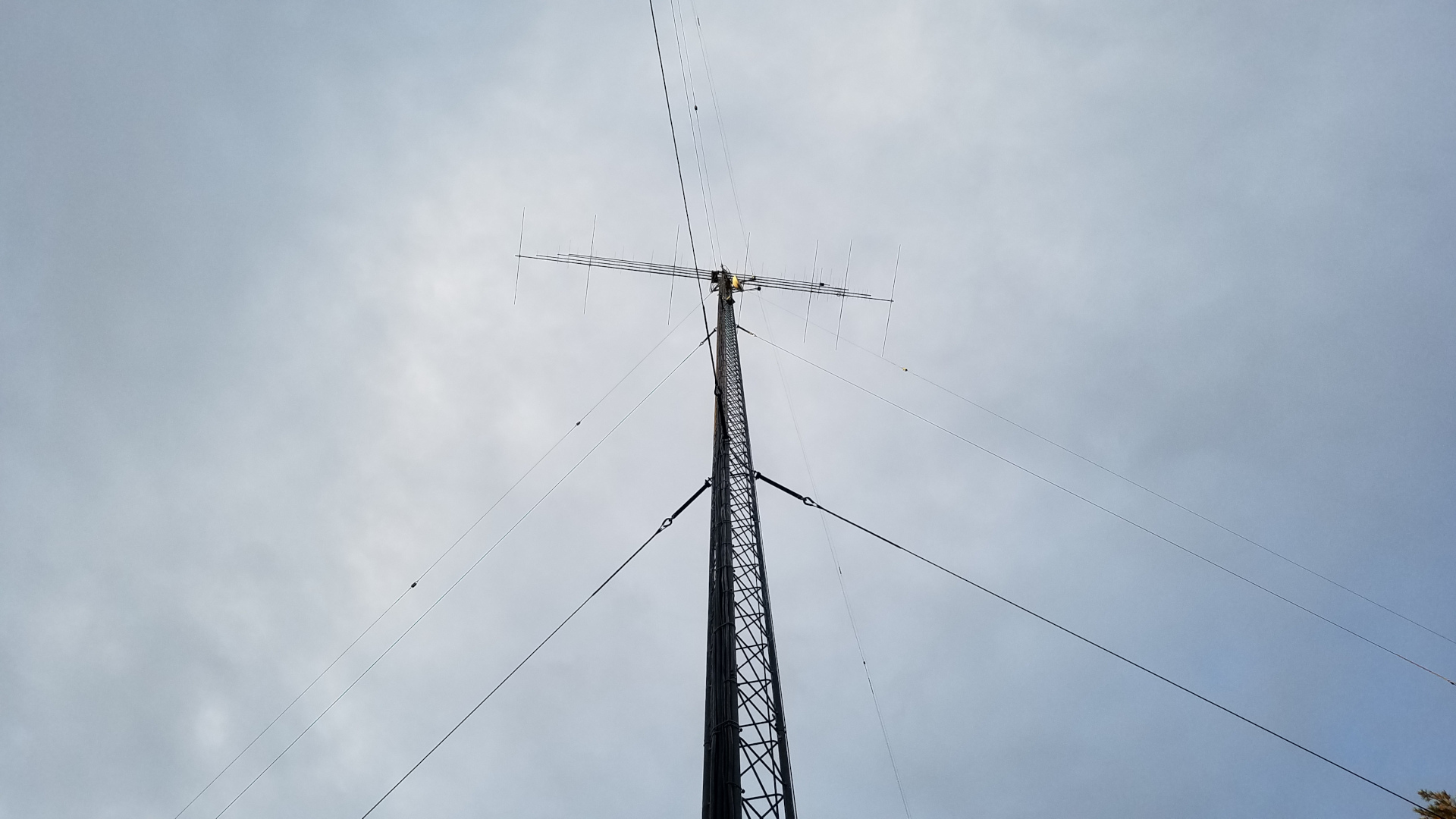
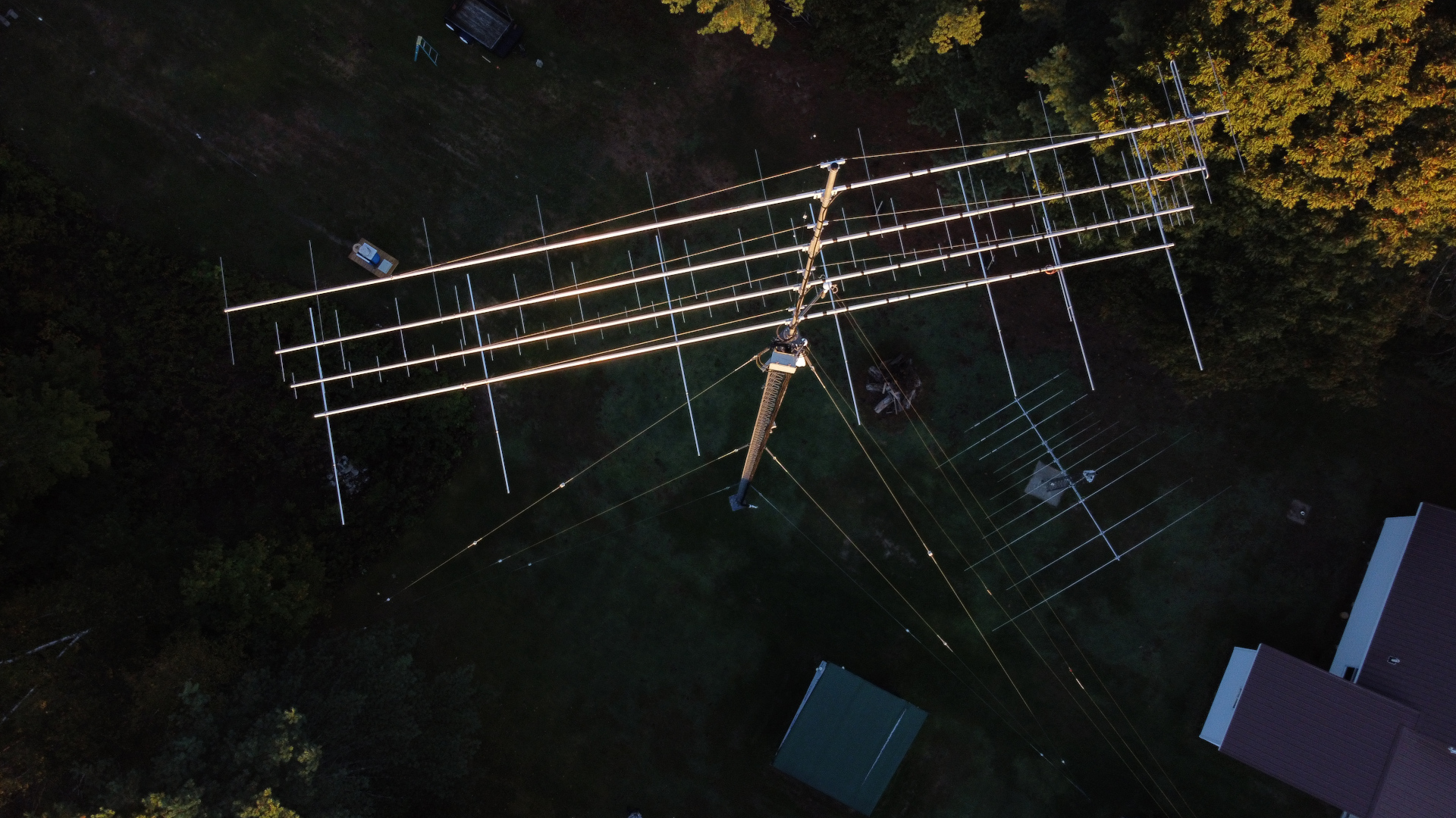
6m antenna waiting on the tram line for first light.Sun’s up! Time to go!VHF/UHF antennas up, northeast tower work finished (mostly).I am happy with alignment of booms on this stack.VHF/UHF stack from above.VHF/UHF stack just after sunset.
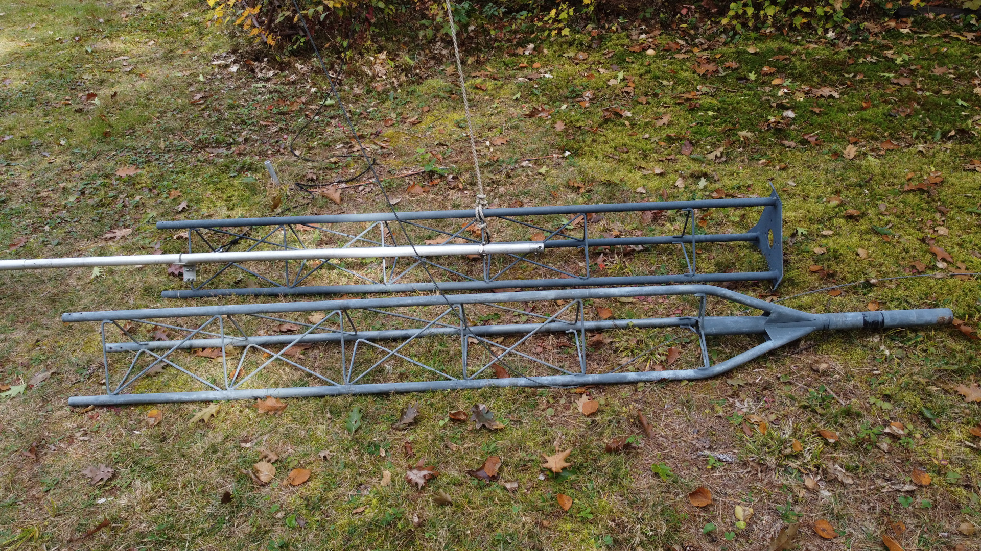
Now it was time to get to work on repairing the southwest tower. I added a temporary set of guys 10 feet down from the top and lowered the regular top set. The first challenge was removing the old mast and rotator. I had to hammer things apart and beat the mast out of the Rohn 25 pointy top section with a sledge hammer! That’s a lot of fun 100 feet in the air. Replacing the tower top section required some special rigging. I had LDF5-50A, 0.84″ CATV line and rotor cable all running up the inside of that tower! There was no way I was going to dig those buried cables up and pull them out of the tower if I didn’t have to. I couldn’t replace the top section using a standard 12 foot gin pole because it lacked sufficient height to lift a tower section straight up and free of the cables. I made a long gin pole out of a 20 foot section of 2 inch 6061 schedule 80 aluminum pipe and mounted it across two tower legs with pieces of 2 inch by 2 inch by 1/4 inch thick galvanized steel angle. As with all tower section lifts, I used a counterweight on the rope below the gin pole to take most of the weight of the section. I attached a length of 1.5 inch OD 1/8″ wall aluminum tube to the braces of the tower top section to act as a lever/handle so I could push it up and off the cables. This worked out pretty well, and the new stop section was rigged the same way for going up and over the cables. In the interim since the tower was first installed I had managed to acquire a 25AG4 flat top section which is far more desirable than the pointy top. After getting the top section replaced, the permanent guys were put back in place and the temporary set removed.
The old top section rigged for removal.The tower without a top section. Well, that looks a bit odd!Old top section and the new one rigged for raising.New top section in place.
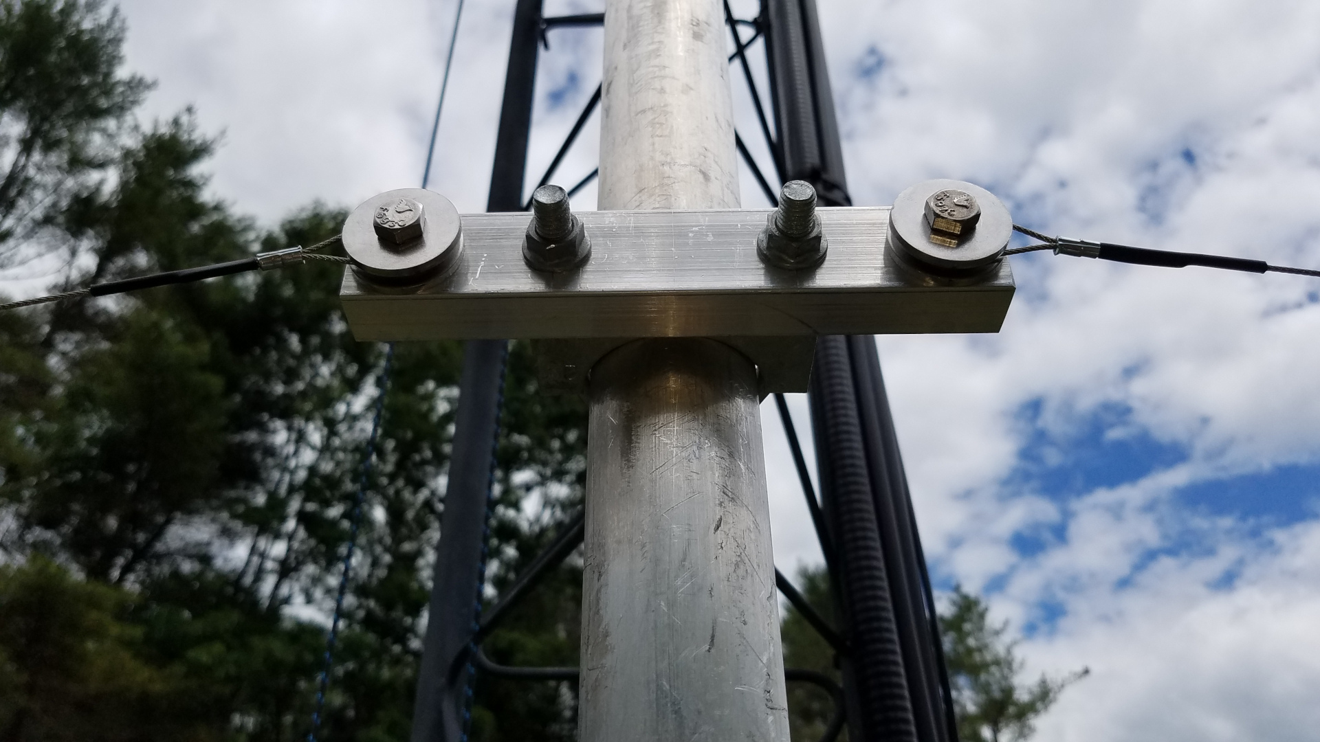
I mounted a proper thrust bearing on the tower top, and put an accessory shelf at the bottom of the 25AG4 for the rotator. In between another accessory shelf was fitted with a centering bearing made of Acetal plastic. I used DX Engineering shelves and I must say they are far better than Rohn shelves! The top bearing is also a DX Engineering product. The next task was getting the new 22 foot long 4130 chromoly mast into place. Weighing 125 pounds it was going to be a challenge for me. I once again used the long gin pole to good advantage. Instead of using counterweights, I rigged a worm gear winch to haul the thing up. This was the one thing I did have help with for about 10 minutes. I hauled the mast up until the top of it was inches below the top of the tower, then had a helper run the winch while I was on the tower for the last 23 feet of lift and dropping the mast into the tower.
The mast ready to be raised.A different view of the mast raising setup.Tower top rigging for mast raising. From this angle, it doesn’t look like a 20 foot gin pole.The winch used for mast raising.Winch mounting. Well, it did work…The mast is in!The gin pole has been removed.
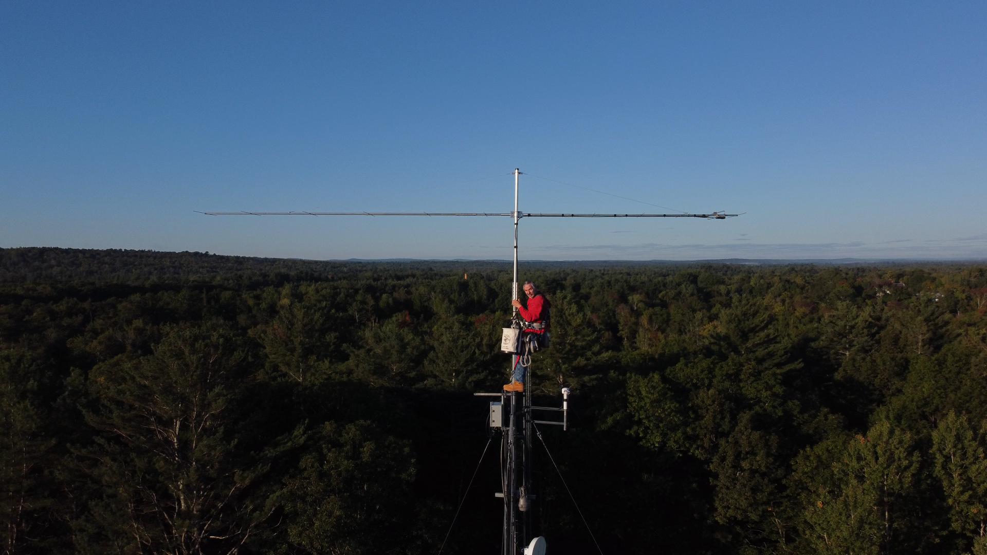
I did manage to sneak an upgrade into the rebuilding effort. I acquired an OptiBeam OB1-4030 rotatable dipole to replace my 40 and 30 meter inverted V antennas that always seemed to have me struggling to work the DX, let alone struggling for contest QSOs. I had been hearing that a dipole beats an inverted V at the same height, so I decided to try this after two failed attempts at home brewing a two band rotatable dipole in recent years. Besides, I was on a campaign to eliminate as many wire antennas hanging off the towers as possible. Skipping ahead, it turns out the improvement is nothing short of incredible! My 40 meter inverted V was at 104 feet, 30m at about 90 feet. The OB1-4030 is at 108 feet on the other tower 145 feet away. I was able to leave the old antennas in place for a while to make comparisons. The OptiBeam beat the inverted V antennas by margins ranging from 5 dB to more than 35 dB depending on the station and time of day! Every time! I have done extensive comparison using the Reverse Beacon Network. I have also experimented with calling DX stations many times with the old antenna and then the new one. Often they continue to CQ while I call time and again with the old antenna but I work them on the first or second call with the new one. I can work DX I never could before and get a much better run going in a contest. This is just amazing! Most of the time I found I no longer needed Beverages for receiving on 40 meters. The exception being during multipath conditions where the CW was difficult to copy. Then the Beverages still provide advantage.
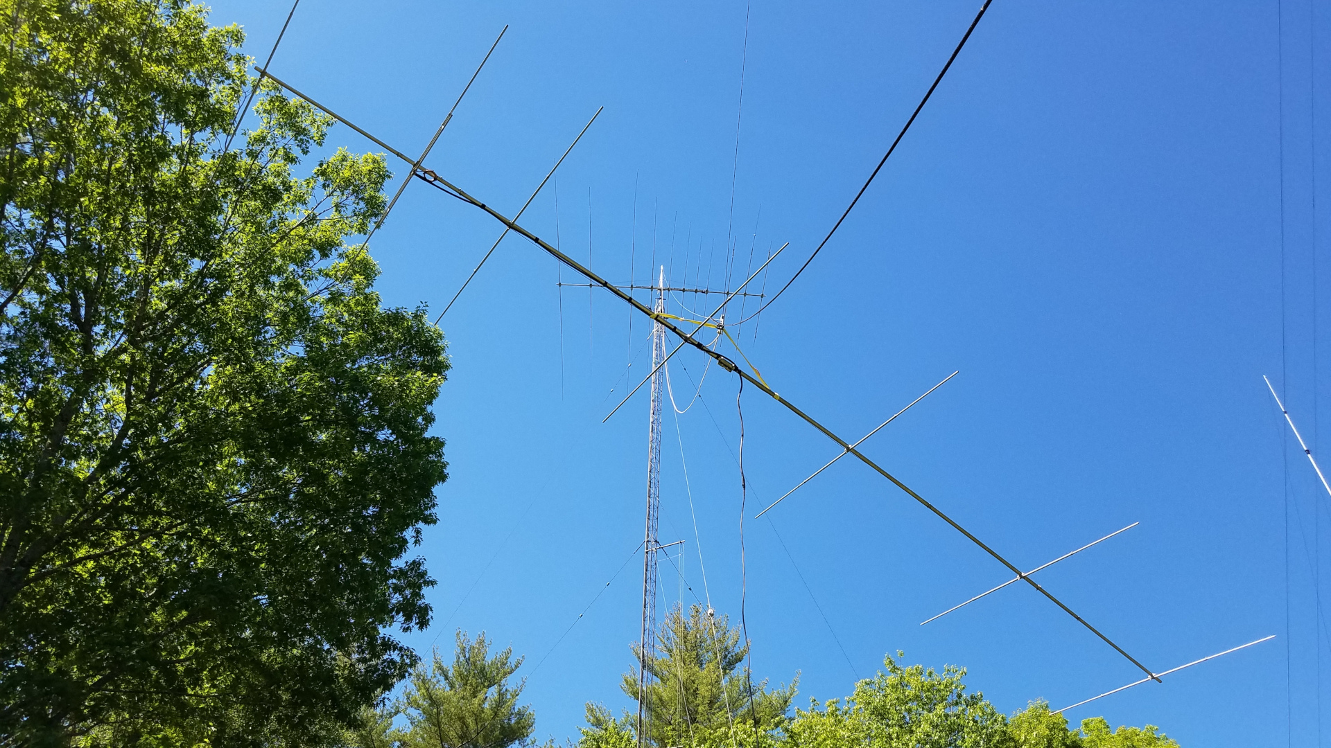
The TH11DX needed more attention than any other antenna. The traps were taken apart, modified with additional screws to reduce wobble, shattered trap caps were replaced and covered with 3 layers of Super 88 vinyl tape, element tips were straightened, coax replaced and the ridiculously inadequate boom truss hardware was replaced with something more reasonable.
Original TH11DX truss to boom clamp. Seriously, MFJ/HyGain?Truss to boom clamp replaced with a DX Engineering part.The original TH11DX truss to mast clamp, which had broken after only one year of service and had to be patched up on the tower. It was nearly ready to break again. Ridiculous.The new home made truss to mast clamp.
Six years ago I struggled to tram the TH11DX up working alone. I did it by hand, wrapping the pull rope around my waist, leaning back and walking backward for the pull. I was pleased to see that now, at the age of 58 I can still do it, and somewhat easier than the first time. That’s odd but I’m not complaining!
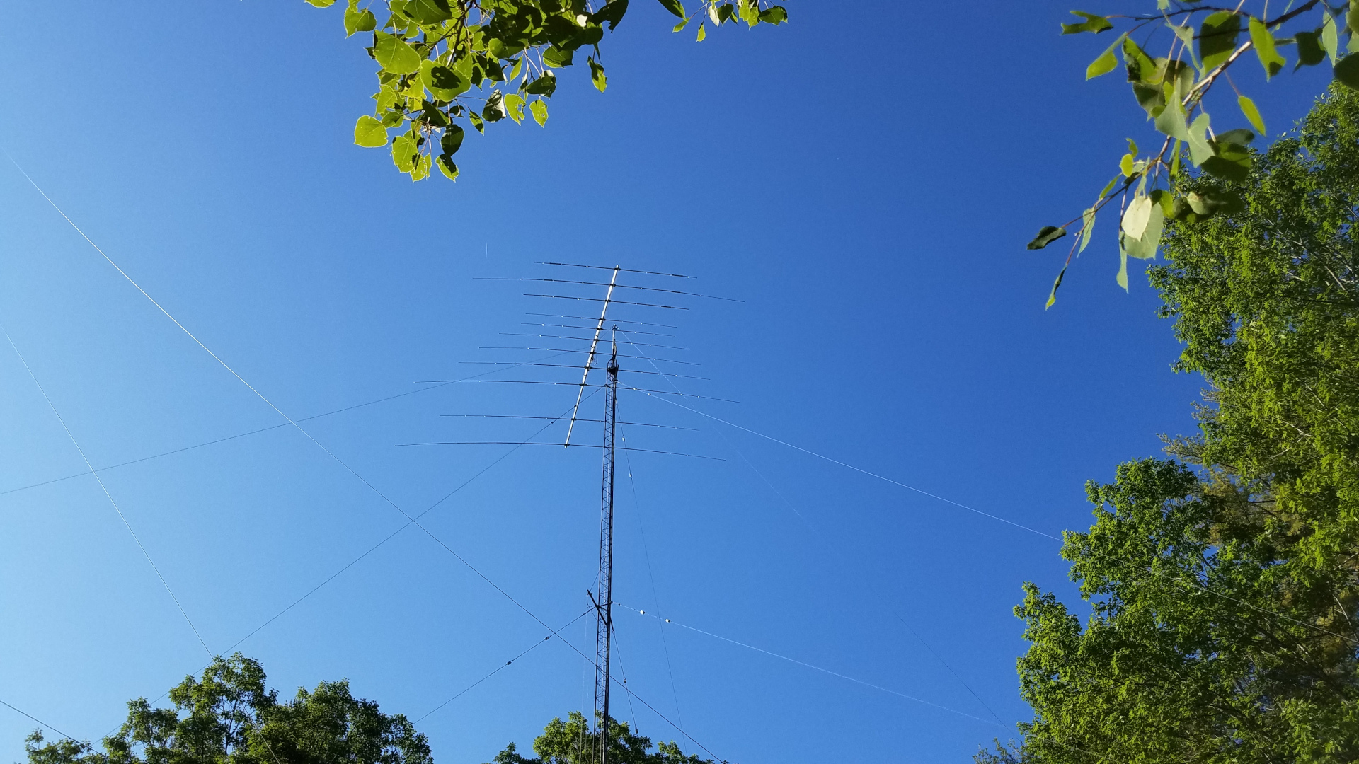
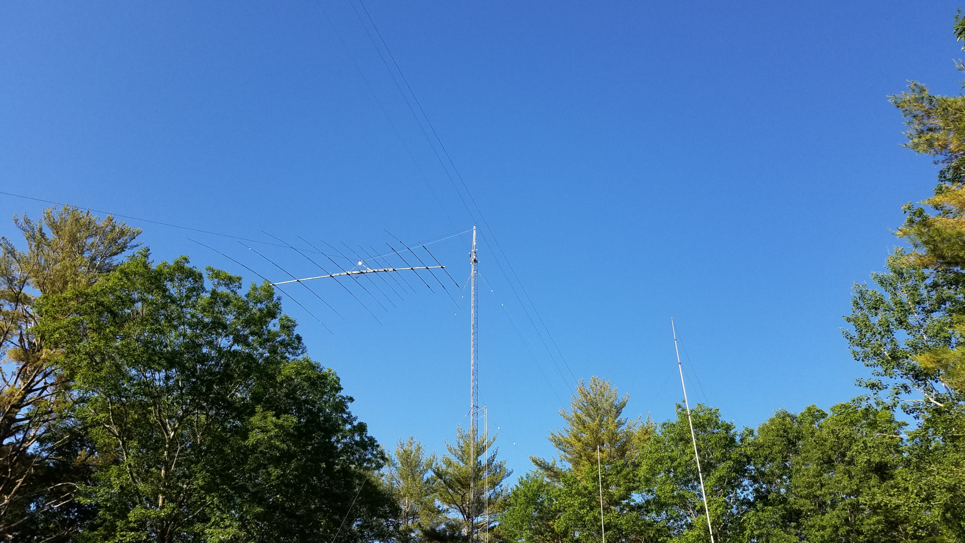
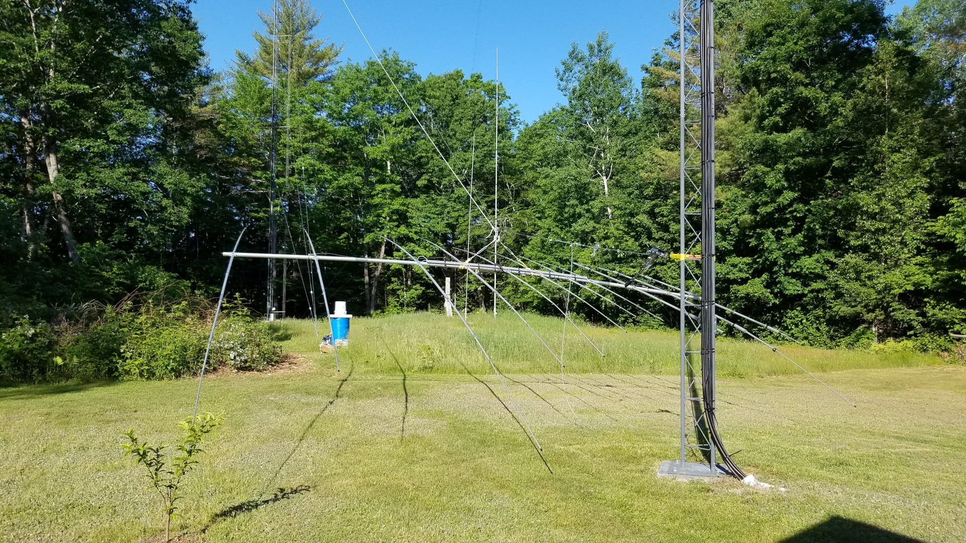
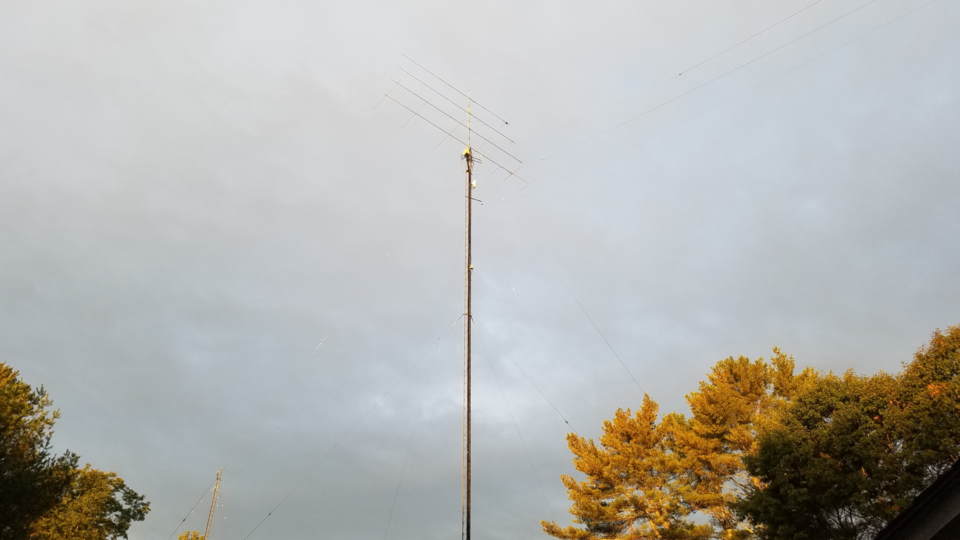
TH11DX on the tram line.Another view of TH11DX on the tram line.Closeup of rigging for TH11DX tramming.TH11DX at the top of the tram line.Final installation, TH11DX at 98 feet, OB1-4030 at 108 feet.
I was concerned about interaction between the TH11DX on 15 meters and the OB1-4030. I had chosen to start without a 90 degree offset to see what happened. I see no detrimental affect. The TH11DX still has a good pattern on 15 meters (and all other bands), SWR is fine, and from what I can tell it is working as well as it has all along. I got away with it!
The last of this work was completed with snow on the ground. As of December 2021 I still have some work to do on low band receive antennas which have somehow managed to develop issues during the a period of disuse. Other than that, all damage has been repaired. 160 meters through 70 cm are back up and running. The loan was a necessary evil but unfortunately it means very limited new projects for a while. During the course of this project, May through December, with great effort and force of will, I was able to lose 40 pounds. By the end of the project my comfort climbing was as good or better than it has ever been.
This is one of a series of “Notes” I published on Facebook. Since Facebook has discontinued the Notes feature, I am publishing that series here on my blog.
The first week of Technician license classes I tell students amateur radio can be a lifelong journey of learning. For some it is a means to an end, be it providing public service or for personal safety while enjoying other recreational activities. For others it is a hobby but not necessarily something that leads to continuous learning or exploration. Then there are those like me. Maybe I have the heart of an explorer. I am quick to dive into exploring a new band or mode, especially if it is challenging. I appreciate and enjoy learning how to do things.
I am by no means an electronics expert. I am in awe of those who understand microprocessor and logic circuits and those who handle RF and microwave design with ease. I wish I understood and felt confident with those things but I have come a long way from the kid whose first project, a key click filter with two inductors and two capacitors, went up in smoke. Today I am able to solve some design problems on my own and occasionally turn junk into something truly useful. As long as my brain will continue to absorb new ideas I will continue to learn about radio and electronics. Sometimes the things I design use older technology because I understand it. Sometimes it is because that is the least costly way to do it. Sometimes both, as is the case with my current project.
I don’t learn well from books or any form of text. I learn better in a classroom, from videos, or best of all from hands on experience. There has been a lot of magic smoke released from electronics here over the years and I have learned much from doing things the wrong way! Many people have contributed to my ongoing education through the years, but Steve K0XP (formerly KO0U) stands out as the greatest mentor I ever had. Through daily email contact in the late 1990s and into the early 2000s, he tutored me on a wide range of subjects involving solid state analog and basic RF design. Steve explained one thing at a time, patiently repeating and rewording until it was absorbed. I have been thinking about that a lot on my recent design project, as it involves a basic concept I finally “got” through Steve’s efforts: using transistors as switches. The drawers full of transistors from which I pulled stock for this were part of an incredible gift Steve found for me.
I call my latest project FRABS (Fool Resistant Automated Band Switching). Everything here needs to be fool resistant. Otherwise the magic smoke gets let out of stuff. This project would be too simplistic for some, too advanced for others. It is within my comfort zone. I admit the design concept using transistor switches is yesterday’s technology. Some would use opto-isolators, some a microprocessor based design. I use transistors because I understand them, I have drawers full of them and they get the job done.
FRABS is almost harder to explain than to build. Last year I started getting back into VHF and UHF using transverters. I have only one station transceiver, which now has to serve for HF and VHF/UHF. I have more than one amplifier sharing a common high voltage supply, and my antenna switching system is somewhat complex, involving both transmit and receive antennas for HF. If I were to forget to put one amplifier on standby before trying to use another, bad things would happen. I once forgot to disable the HF amplifier and dumped 1500 watts of RF into a hybrid transverter drive attenuator rated 250 watts. Zap! So much for that device. Clearly simple wasn’t going to do it here. Simple can be good, as in keep it simple, stupid. But simple isn’t always fool resistant.
What I needed was some means of automating the various tasks involved with switching bands: route RF to the proper places, enable one amplifier while ensuring that all others are disabled, etc. I needed the added protection of having it only available through the automated system, with no manual method that the fool might use instead to blow stuff up. After some discussion with Dave, AA6YQ, developer of the extraordinary DXLab suite of software I have running in the shack 24/7, transverter support in Commander (DXLab’s transceiver control component) was extended to include all bands I planned on adding. Since Commander understands transverters, can control the radio through its CAT command set, and can control external devices through a parallel port I had the method of control. All I needed was to add a parallel port to my PC and to come up with an interface to take signals from that port and control the station switching.
The project started with a concept drawing. I have no time or patience for computer drafting, so I grabbed a piece of paper and started scribbling. This, with its somewhat cryptic notations, is what resulted. It gave me a clear overview of what I was trying to accomplish.
Fortunately I had a vacant PCIe slot in the PC. After some research, reading reviews, etc. I settled on a Rosewill RC-302E parallel port adapter. USB parallel adapters do not work in this application! They are printer drivers and do not provide low level access for “bit twiddling” that is necessary for this application. I was concerned about how much current could safely be drawn from the Rosewill since not all these adapters are created equal and none are designed to source current. I was going to need a couple of milliamps to control my interface. Testing revealed that this one can provide more than three milliamps with virtually no voltage drop. Very good! It took about 10 minutes to set up custom band switch buttons in Commander.
I didn’t need to use any sort of decoder or digital to analog device. The parallel port has 8 data bits which can be controlled by Commander. I needed only seven “states” for this project: HF, 50, 144, 222, 432, 903, 1296. That meant that I could use a single data bit for each state by having Commander write the appropriate value to the port to make a single bit (pin) go high. I used the following seven values: 1, 2, 4, 8, 16, 32, 64. A value of 1 causes pin 2 of the DB25 port to go high, or about 3 volts, while all others remain low, zero volts. A value of 2 causes pin 3 to high, 4 causes pin 4 to go high, and so on. Nothing could be simpler than that. I have the most significant bit, pin 9 (128) left over for some possible future use. I may end up using it in some way for our new 2200 and 630 meter bands.
I had already decided this was going to be a low budget project, making use of parts I already had. I was going to need both NPN and PNP transistors for the switching circuits. I had drawers full of PN2222, PN3904 (NPN), PN2907 and PN3906 (PNP) transistors. A quick look at the relevant data sheets indicated the PN2222 and PN2907 would be the better choice for this project. I got down to business working out the details of the hardware interface.
For HF (160-10 meters) and 6 meters, there wasn’t much to be done. Those bands are native to my station transceiver, the transverter select relays would all be de-energized for these bands, and I didn’t need sequencers. All that would be needed is a simple switch to enable the proper amplifier.
HF and 6 meters were easy, since those bands are native to my transceiver and very little switching would be needed. The higher bands (144, 222, 432, 903, and 1296 MHz) would require a bit more. There I would have to route RF to the proper transverter, one path for transmit, another for receive. I would also need to use a sequencer for these bands since fast (vacuum) relays become problematic or completely impractical and there would eventually be complications such as tower mounted receive preamplifiers. This means things need to be switched in a specific order with time delays when going from receive to transmit and vice versa. T/R sequencers are the usual way of doing that, and since a kit is readily available for $20 I wasn’t going to design my own. After evaluating what would be involved with using a single T/R sequencer on multiple bands, I opted to use one for each band. The switching would be simplified and I could adjust the step time delays independently for each band if I needed to.
The 2 meter (144 MHz) switching circuit. This same circuit is dupliated four more times for 222, 432, 903, and 1296 MHz. It’s a good thing I had those drawers full of transistors!
I was also going to need a drive attenuator for the transverters. They require a few milliwatts of 28 MHz drive. Putting the full 100 watts from the transceiver into them would surely let out some of the magic smoke! I was fretting about not having a needed resistor when some tutoring obtained through one of the VHF discussion forums reminded me of something Steve had taught me years earlier: the capacitive voltage divider. Straight out of the junk box an adjustable drive attenuator was built. The final implementation involves having the band select buttons in Commander set the transceiver power output to 10 watts and using 30 dB attenuation to drop that to 10 milliwatts. Perfect.
Circuit for the drive attenuator. C1 allows this to be adjustable from 27 to more than 50 dB attenuation. I’ve set it for 30 dB in my application.
FRABS isn’t completely finished at this point. It is up and running to the point of proof of concept. I have been using it to toggle between HF and 2 meters for the past few days and it is doing what I designed it to do. There were a couple of glitches on this mission. The smoke came out of an ancient transformer I used in the FRABS power supply, but digging a little deeper my junk box provided a more modern unit that turns out to be better suited anyway. I also had a brain fart and forgot to include base current limiting resistors for the PNP transistors in the first draft design. Poof! Oops! I just wasn’t thinking. I know they are required, and I knew instantly what I had forgotten when the first test failed. What is not shown on the schematics is a liberal sprinkling of bypass capacitors to keep any stray RF out of semiconductor junctions where it could cause all sorts of mayhem.
Inside the transverter drive attenuator. I liberated the type N and BNC jack and cable assemblies from an old Motorola MICOR UHF antenna network.
Thge assembled transverter drive attenuator. The heat sink was also liberated from an old Motorola MICOR UHF antenna network.
Inside the partially complete FRABS control interface during testing. There is one more large board to be added (it wil stack on top of the one at the upper right) and four more of the small green baords (T/R sequencers), not to mention a lot more wires.
Bottom view of the FRABS control interface during early testing. Eventually there will be cables plugged into most of those connectors.
The relays used to toggle the station from HF/6m to the higher bands are shown here mounted on a rack panel. It’s a bit messy in here. Cables going here, there, everywhere.
The transverter drive attenuator (left) and transverter select relays (right) mounted on the inside of a a multi-function rack panel. The wiring across the top of this panel is part of 12V DC power distribution to network components (unrelated to FRABS). Cables will be color coded by band. Here, white heat shrink tubing is used on cables for 144 MHz.
The 2 meter gear (minus that unrelated thing at the lower left) currently sits atop the rack mounted station PC.
This project is neither pretty nor elegant, but it does make station operation much simpler and more enjoyable. It also helps pave the way for adding bands with a minimum of fuss.
This is one of a series of “Notes” I published on Facebook. Since Facebook has discontinued the Notes feature, I am publishing that series here on my blog.
I’m pretty self sufficient when it comes to problems; I create my own. Every once in a while, though, I get a little outside help…
I set out to build a bandpass filter for the 136 kHz band. Fortunately my junk box yielded all of the necessary parts and it didn’t take long to construct the simple circuit. As an interesting side note, when seeking capacitors for RF projects that aren’t in my “new parts” stash, I usually have to dig through RF boards out of old receivers and/or transmitters. This time, I had to get suitable components from audio boards! That says something about just how low in frequency this 2200 meter band is! In fact, some hams have successfully used high end audio amplifiers as RF power amplifiers for this band!
Since I now have test equipment, I avail myself of it whenever possible. The first thing I did is put my new filter on the tracking generator/spectrum analyzer, expecting to see a lovely bandpass response matching what I had seen in the filter design software. Whoa! Something was wrong. Instead of a flat response in the 100 to 200 kHz range, dropping steadily and steeply above and being nearly 70 dB down at 600 kHz, there was a “peaky” response in the desired range with a very sharp secondary peak at 465 kHz and a moderately steep roll-off above that. Response was down only 43 dB at 600 kHz. I checked return loss (SWR) and that was awful too. What could be wrong?
After verifying the circuit layout and marked component values, I realized I must have a bad component or perhaps the type of capacitors I used wasn’t working well in a filter circuit. I poked and prodded, changed out all of the critical capacitors, but there was no improvement. In desperation I resorted to something which probably isn’t an approved troubleshooting technique: bypassing components with a wire one at a time while watching filter response on the spectrum analyzer. Bypassing any part changed the response, but only one caused the spurious response at 465 kHz to vanish. I wasn’t at all sure this meant anything, but it did seem curious. That part was one of three inductors in the circuit. It, like the others, was wound on a small FT37-43 toroid core. Thinking somehow this inductor was messed up, I wound a new one using a different type of wire. This still didn’t change anything.
After much head scratching and pondering, I was running out of ideas. The only thing that made any sense was that somehow that inductor was the wrong value. But how could it be? Since nearly all of the different ferrite mixes (materials) used in these cores look alike, it was theoretically possible that a core of some material other than #43 had worked its way into the bag. That didn’t seem likely since this was a still sealed bag of cores I bought from a major supplier some time ago but hadn’t used until now. Nevertheless, it was worth investigating the possibility since I had no other clues.
I went back to the filter design software and began experimenting with different values for this one inductor. It was supposed to be 47 microhenries. I found that if I changed it to 8 microhenries in the filter designer, the calculated response was almost exactly what I was seeing in the real world on my test equipment. Interesting! The question then became whether the same number of turns it takes to get 47 uH on a FT37-43 core would yield 8 uH on an FT37 size core of some other material. Lo and behold! The same number of turns on a core of #61 material gave exactly that much inductance! It was starting to look as though I might be on to something with this “wrong core” theory. Most of my theories aren’t as promising.
I wound a new inductor using another core from the same lot and put it into the circuit. Nothing changed. I tried another with the same result. Then I decided to get serious. I calculated how many turns it would take on a #61 core to get 47 uH, and wound one accordingly. I had to use really small wire since a much larger number of turns was required. With this inductor the filter response changed to what it should be! I did indeed have some #61 cores in this lot of supposedly #43 cores! Further investigation (involving a lot of coil winding and soldering) revealed that the lot of cores were about a 50/50 mix of the two types. I swear this was a sealed bag from the supplier until I opened it to make this filter. Either the supplier or the manufacturer must have got some #43 and #61 cores mixed up.
In the end I have a perfectly working filter with flat response and less than 1 dB insertion loss across the 100 to 200 kHz passband, rolling off steeply on either side and reaching -70 dB at 600 kHz. It continues to roll off steeply, reaching almost -90 dB at 800 kHz. Return loss in the passband is good at -20 dB or better. The circuit board and construction technique is crude but at this frequency it just doesn’t matter. One of the nice things about building and experimenting in this part of the radio spectrum is that you can get away with a lot of sloppiness. You cannot get away with a 600% error on inductor values in a filter, though. Well, maybe you can if you don’t mind using a relatively poor filter.
I questioned the wisdom of investing in test equipment a few years ago. I really couldn’t afford it. There are still times I wonder if I can afford to keep it. But it has saved by sorry butt more times than I care to admit! I often wonder just how I got by all those years without it. Skill? Luck is more likely! I don’t see how I would have spotted this problem without the test equipment. Undoubtedly I would have placed the filter in service assuming all was well, and never known that it was not performing as intended.
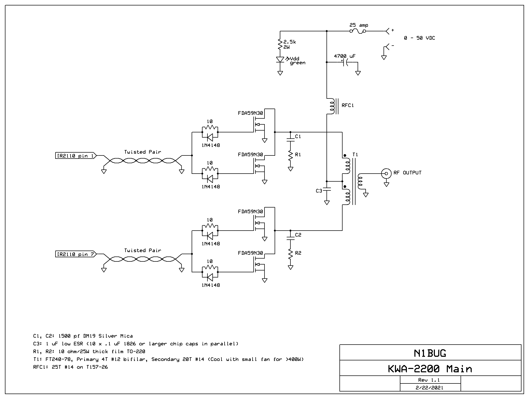
The amplifier. This was a “junkbox special”, so yes it’s a bit ugly!
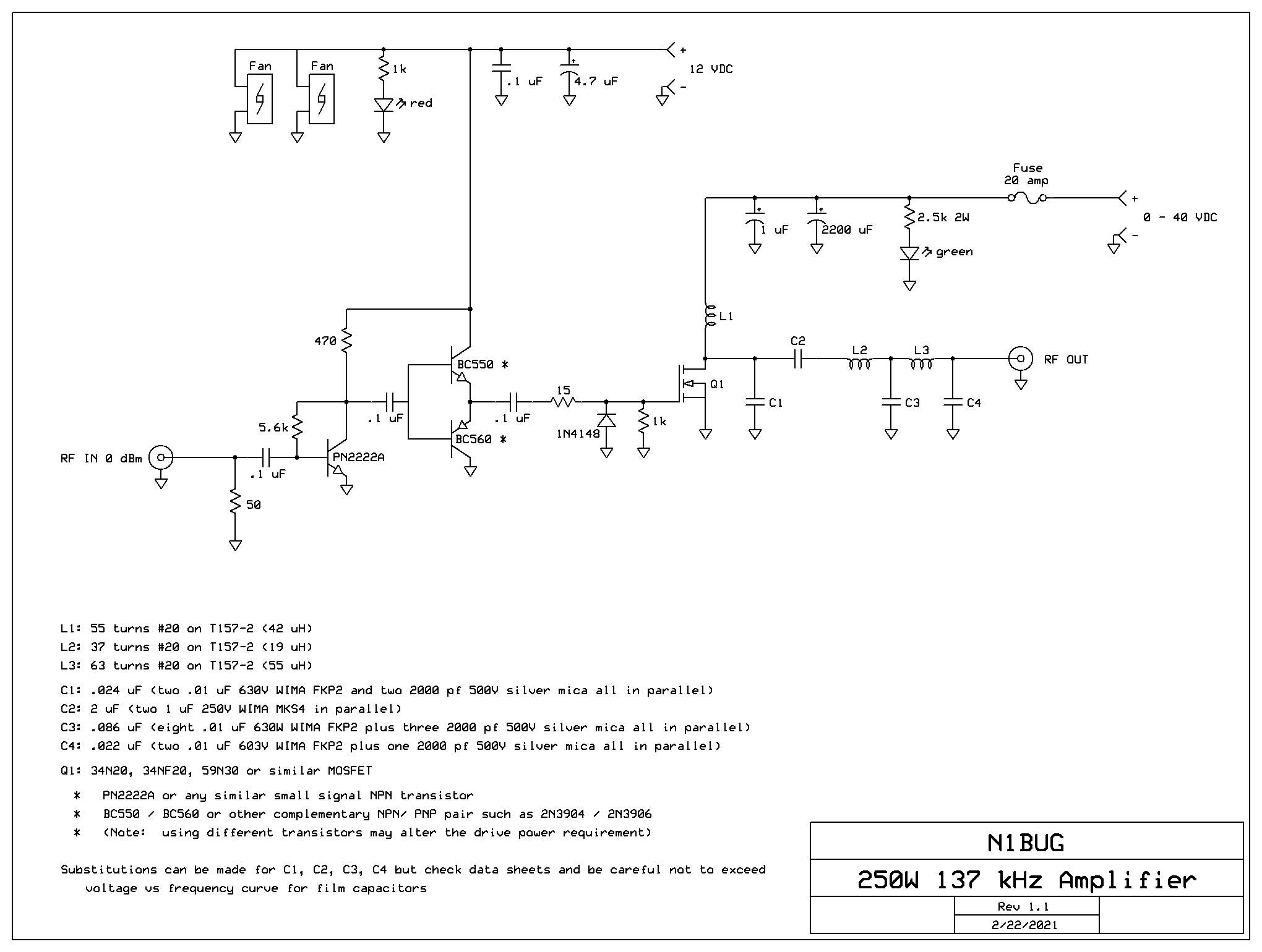
This is an update to an earlier blog post describing a moderate power 2200m class E amplifier with very low drive requirement. The design had been evolving for some time but is now in a finished state as far as I am concerned. In its current configuration I have many hours on this little amplifier running 250 to 275 watts RF output, including numerous nights running 80% or higher duty cycle for hours at a time. It has proven to be very reliable. The basic design requires just 0 dBm drive (one milliwatt), but I have included a built in 20 dB attenuator in mine to accommodate the +20 to +24 dBm drive provided by my various exciters.
Amplifier schematic. The 20 dB input attenuator I included in my unit is not shown.
Use caution when selecting capacitors for the output circuit, namely C1 through C4. It may be very tempting to use a single capacitor of the specified value, but doing so will likely mean operating the capacitor beyond its voltage ratings if it is a film capacitor. Film capacitors must have their voltage derated as frequency increases. Capacitor data sheets usually have curves for this derating. I had capacitors in a 630 meter amplifier fail because I had not taken that into account. Generally smaller value capacitors can handle more voltage at a given frequency than higher value ones, which is why I use several low value capacitors in parallel to reach the desired capacitance.
When selecting a FET, choose something rated 200 volts or more if you plan to run this amplifier at full power. Voltage peaks at the FET drain are about 3.5 times the applied DC voltage. So with 40 VDC on it, the FET is going to see a peak voltage around 140 volts on every RF cycle.
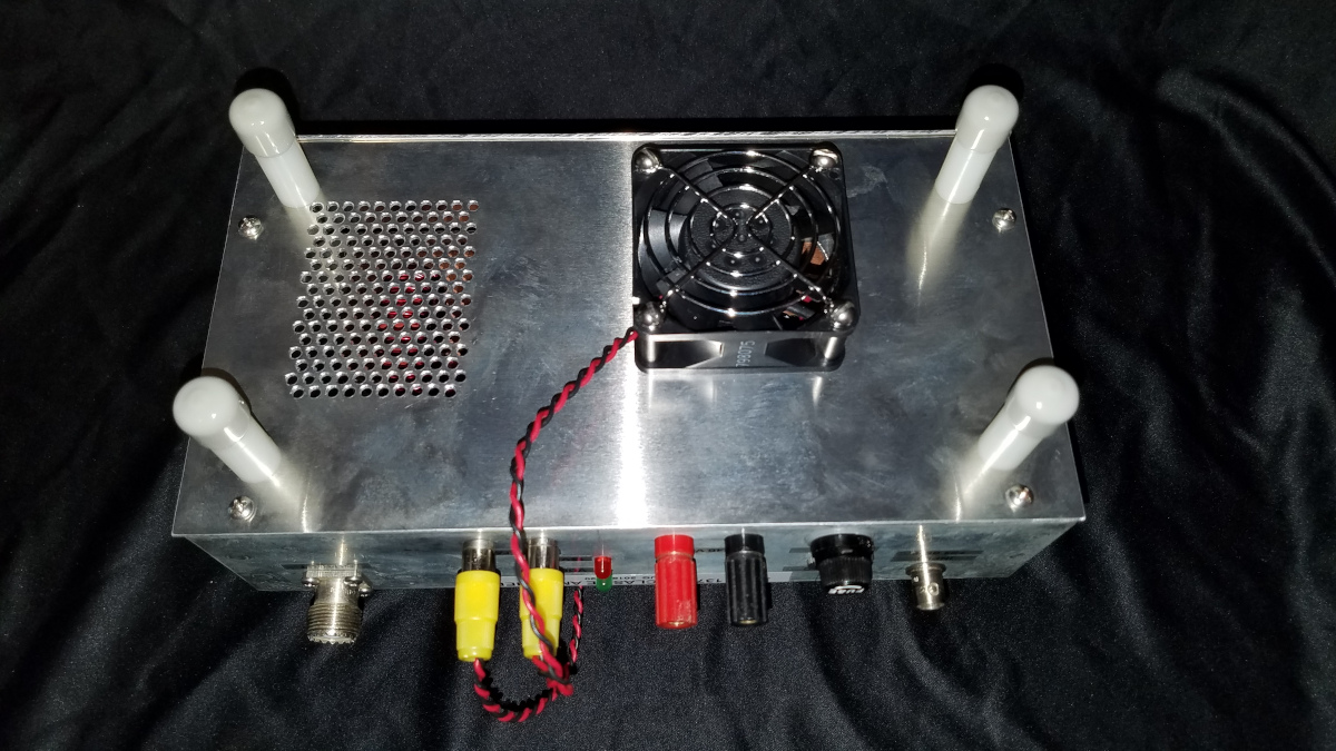
The FET requires good heat sinking. I prefer either directly mounting the FET with a bit of thermal grease to a heat sink isolated from ground (note the heatsink will have drain voltage and RF on it, so be careful what might come into contact with it) or a mica insulator with thermal grease for a normal grounded heat sink. I do not recommend using greaseless Sil-pad thermal pads as they may be unable to provide adequate cooling efficiency. The heat sink on my amplifier is about 5 x 3 x 1.5 inches. A fan on the heatsink is not required for low duty cycle such as two minute WSPR transmissions at 33% or lower duty cycle. For long T/R period modes or frequent transmission resulting in high duty cycle, you will need either a larger heatsink or a fan. I also have a fan on the bottom pushing air into the amplifier and air exhaust vents on the other end. Again, this is not needed for short transmissions of low duty cycle but if you are going to run 15 or 30 minute modes or very frequent transmissions, it will be necessary to supply cooling air to L1 and L2. I also have an internal fan assuring high volume air flow across those inductors, though that is probably not needed. It was there to move air across the inductors before I added the bottom cover and intake fan, and I didn’t bother removing it.
Bottom view of the amplifier showing the fan and air exhaust
As noted in the previous post, this amplifier was constructed by making “islands” in a solid copper plated PC board using a Dremel rotary tool. Other methods will surely work as well.
Internal view of the amplifier
The only future change I might make is to replace the little TO-220 size 34N20 FET with a FDA59N30 in the larger TO-3P package. I have not experienced any FET failures with the present configuration but I like the larger FETs for better cooling efficiency.
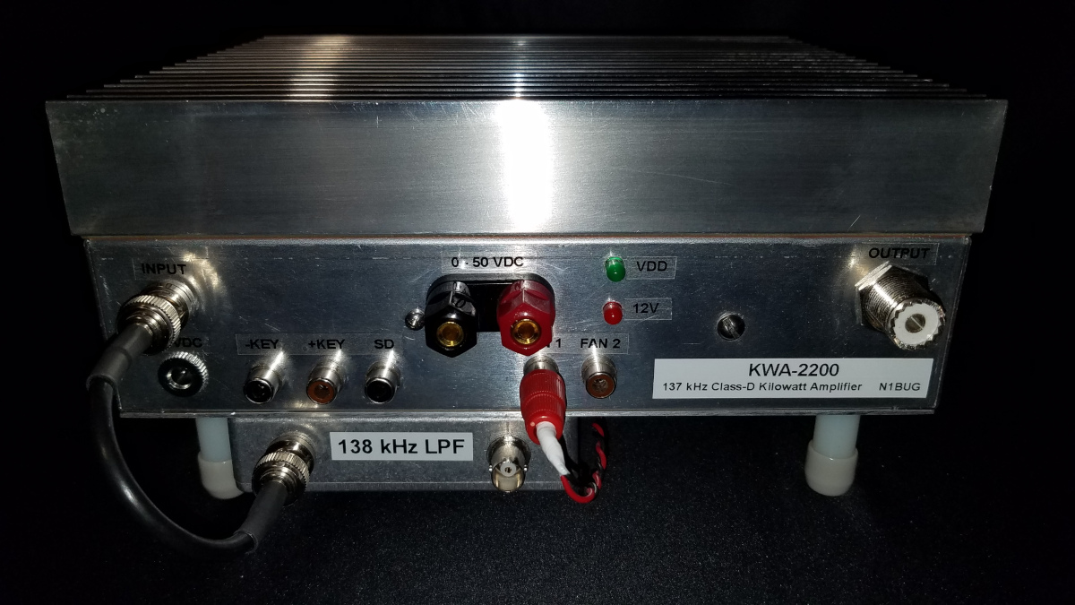
The story of this amplifier starts back in 2017 when I held a FCC Part 5 experimental license (WI2XTC). This was prior to FCC granting amateur privileges on 2200 and 630 meters. I was looking for a kilowatt-class amplifier that seemed reasonably easy and inexpensive to reproduce. I settled on the W1VD kilowatt class D design.
After building the amplifier I had a lot of problems with blown FETs. After many months of testing, troubleshooting and trying various things, I got that problem under control for the most part. It turns out this was not a problem with the design or my construction, but simply that modern modes and operating practices are not consistent with the intent of the design. The amplifier was designed for a steady RF signal at its input, with transmission to start and stop by using one of the keying inputs to enable and disable the FET driver IC. That just isn’t how modern computer generated modes work. The software usually provides for PTT (amplifier keying), but it is the opposite of what would be needed to keep the amplifier happy. PTT is asserted before RF generation starts and held until after RF stops. The amplifier needed the opposite to be safe: PTT asserted after the start of RF generation and released before RF stops.
Initially I was experiencing frequent FET failures with any exciter I used, but they were far more common, in fact almost guaranteed using an exciter capable of amplitude shaping the start and/or end of the RF envelope. I don’t have a storage oscilloscope, but after seeing some FET drain waveforms provided by other users of the same amplifier it was apparent there were (or could be) voltage spikes exceeding the 200 volt rating of the FQP34N20 FETs at the start and especially end of a transmission. Additionally there appeared to be extended times of zero voltage on one pair of FETs or the other, possibly indicating a longer than normal on time. One might wonder if there were current surges occurring at those times. After a lengthy search for replacement FETs rated for higher voltage and current but otherwise having similar ratings to the FQP34N20, I tried the FDA59N30. That eliminated any blowing of FETs with exciters or modes that are not capable of RF envelope shaping, such as the QRP Labs Ultimate 3S which I use extensively. I had just one FET failure in more than a year of operation. It appeared that may have been due to overheating. I found the mounting screw on the failed FET was not tight. Both the mounting surface of the FET and the Sil-Pad underneath were discolored in a way that suggested excessive heating. The FDA59N30 is a current production part while the FQP34N20 is long discontinued and becoming very hard to find except from some overseas sources which are selling counterfeit devices.
During the summer of 2020 I was invited to join the early testing team for the new FST4 and FST4W modes being developed for use at LF and MF. It was one of the better things to happen in 2020! Initially I was able to run these modes using the phasing exciter but I noticed some peculiar glitches on the scopematch (sophisticated RF power and SWR monitor using an oscilloscope) at the start and particularly at the end of transmissions. I also had some intermittent problems with amplitude and phase fluctuations during FST4/W transmissions. Eventually while looking for the source of that problem, I discovered the IR2110 FET driver was not entirely healthy. One side was OK but the other was providing only weak gate drive to the FETs. I replaced the driver and that was the end of being able to transmit using the new modes! FETs were constantly meeting their demise with the new modes, while other modes were OK. My pile of dead FETs was again growing rapidly! At about the same time I learned something about the new modes that I had not previously known. They were intentionally using envelope shaping at the beginning and end of transmissions! (Note: with the general availability release of WSJT-X 2.3.0, the FST4/W envelope shaping can be disabled.) Sure enough, when I tried manually enabling the FET driver after the envelope shaping at the start and disabling it before RF shaping commenced at the end of transmissions, FETs did not fail.
It has never been clear to me exactly where in the amplifier problems start with non-constant amplitude drive, but clearly bad things were happening somewhere. Was it strictly in the output circuit, or was something going wrong in the driver or the pre-driver logic? It would be fair to say I was never entirely happy with the configuration of the amplifier anyway. Since it used a flip-flop to clock the IR2110 FET driver, it required the RF input signal to be at twice the operating frequency. For 137.5 kHz operation, it needed RF drive at 275 kHz. In order to achieve that with common exciters and relatively minimum hassle, I used a frequency doubler circuit before the driver. That always seemed like unnecessary complexity to me, but at the time of construction there were few, if any alternate driver designs for class D amplifiers that didn’t use a flip-flop, therefore requiring drive at twice the operating frequency. The doubler also caused some problems running EbNaut, which uses 180 degree phase shift keying.
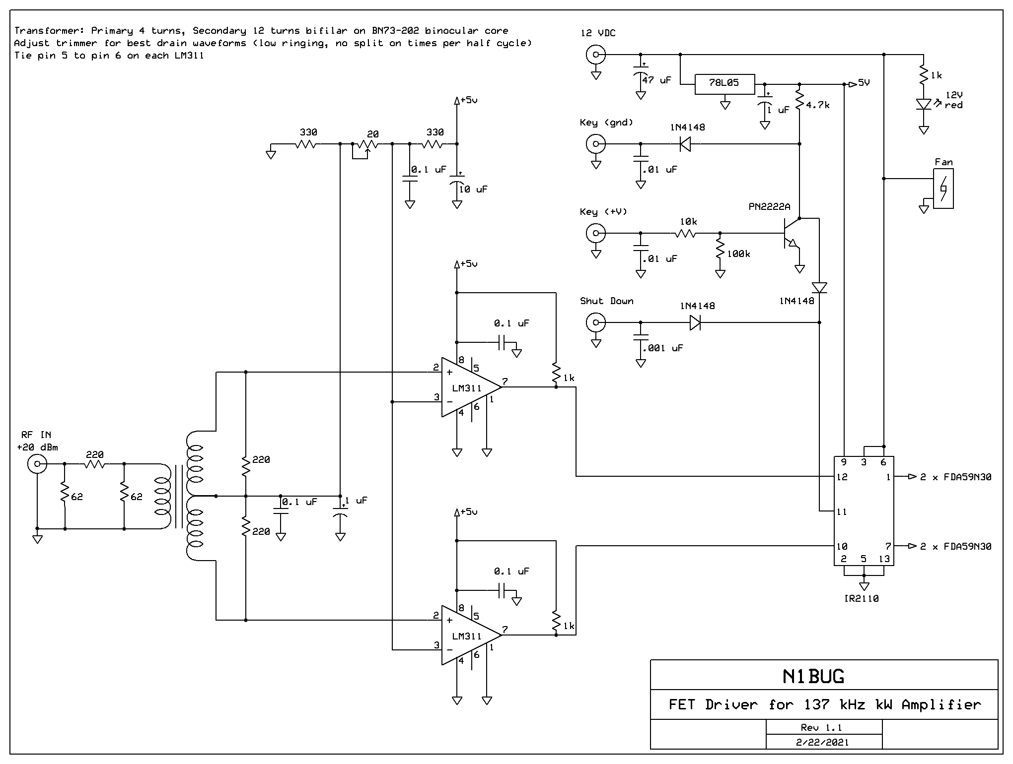
While struggling to think of a solution to the FST4/W envelope shaping killing FETs en masse, it came to my attention that others were now using drivers for class D amplifiers that did not use the flip-flop and worked with “normal” drive at the operating frequency. I decided to try an experiment. Melding elements from three different designs, I came up with a driver that provided all of the control inputs of the original, required no doubler and allowed for some adjustment of the duty cycle. The circuit uses a 1:9 impedance step up transformer driving a pair of LM311 comparators. The comparator outputs control the IR2110 FET driver. One obvious advantage is that this does not require drive at twice the operating frequency. Another is that, unlike the original driver configuration this one allows for some adjustment of the length of the drive pulses to the FETs. This made it possible to get cleaner drain waveforms with less high frequency ringing.
New driver circuit for kilowatt class D amplifier
With the original driver there was always some high frequency drain ringing. With this driver it can be almost entirely eliminated by adjusting the 20 ohm trimmer to vary the duty cycle or length of drive pulses. There is a tradeoff between the circuits. The original amplifier input consisted of a frequency doubler and the flip-flop preceding the IR2110. With that configuration there was little to no change in drain waveforms over a 15 dB drive power range. With the new circuit, drain waveforms change with drive level. The change is minimal over about a 6 dB range but increases outside those limits. The range of acceptable input can be pushed to 15 dB before things start looking really alarming. This worked fine for all but FST4/W modes (prior to the 2.3.0 GA release with envelope shaping disabled). With FST4/W slowly rising from zero to full power at the start of a transmission and slowly decreasing from full power to zero at the end, the drain waveforms went through some ugly periods. I was still occasionally losing FETs.
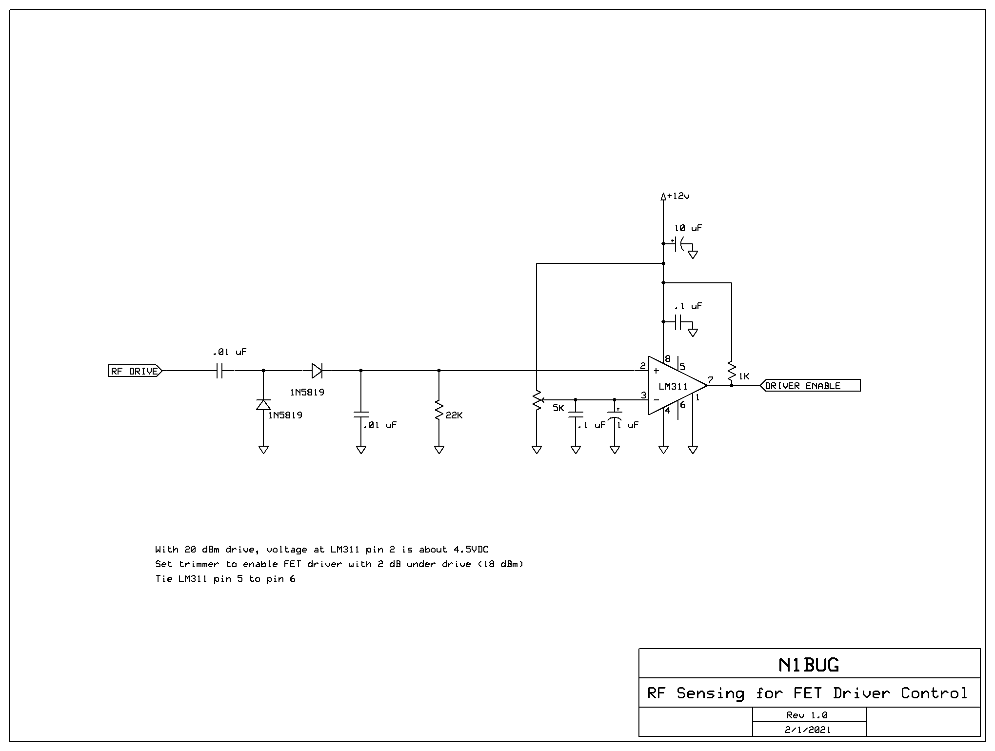
I wondered if an RF sensing circuit could solve that problem. It should be possible to sample the incoming RF drive, rectify it and use the resulting DC voltage to control a comparator which would enable the IR2110 only after drive had reached a safe amplitude. The question I had was would it be fast enough to disable the FET driver at the end while the envelope was decaying. If it was too slow, it might not disable the driver before the amplitude reached a low enough level to cause problems. Never blindly trust my math or circuit design skills but by my reasoning it looked possible. The envelope shaping occurs over approximately 2.5 seconds for a FST4/W 1800 second transmission. I believe it scales linearly with the T/R period, so for the 15 second transmission it should be about .02 second. There should be plenty of time to shut things down if I used an RC time constant of about .0002 second. Instead of rambling though all of my rough calculations let me just say I tested the circuit as built with several hours of FST4-15 transmissions, which would require the fastest timing. There were no glitches evident and no FETs were harmed during the test.
RF sensing and comparator circuit. The driver enable output is internally connected to + Key on the above driver circuit.
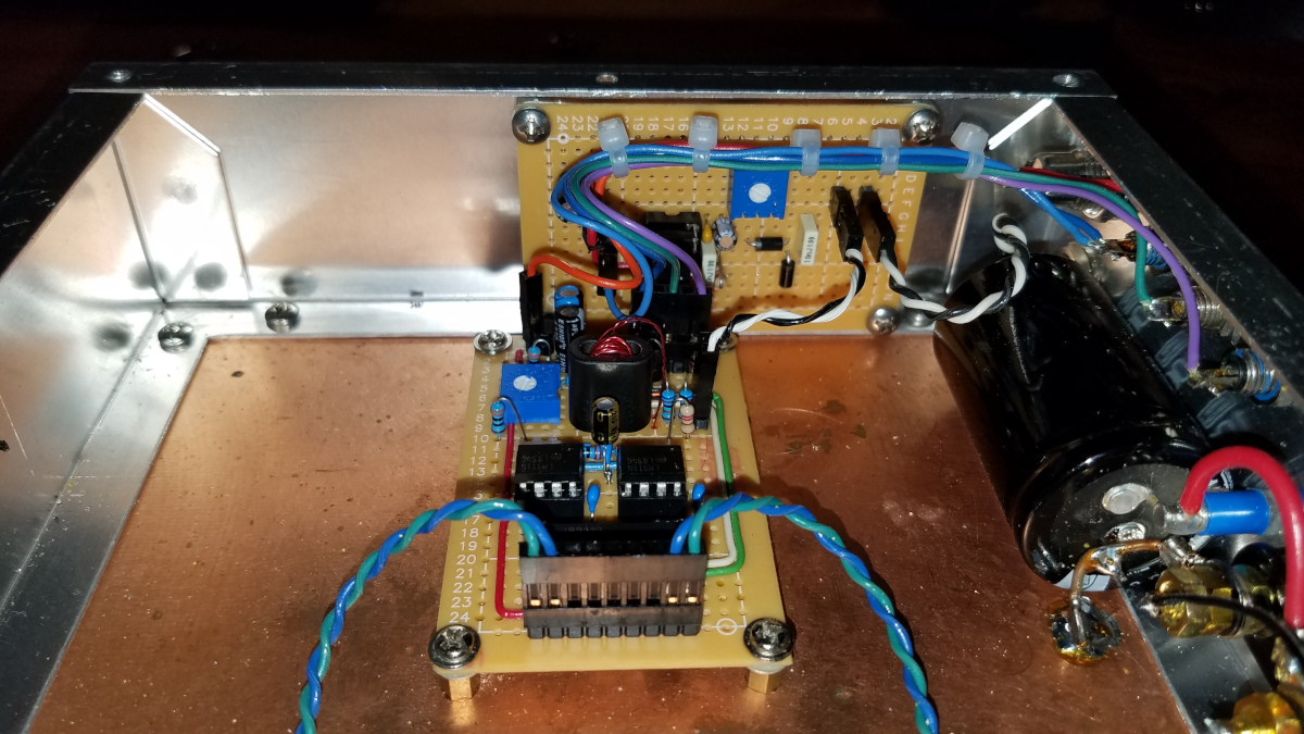
I built the new driver circuit on a board which was the same size as the original and used the same connectors, so it was a drop in replacement for the amplifier. Similarly the RF sensing and control circuit is a drop in replacement for the no longer needed frequency doubler.
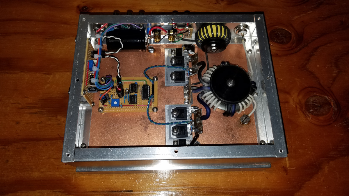
RF sensing (mounted vertically on chassis end wall) and driver (foreground) boards mounted in the amplifier. Blue and green twisted pairs go to the FET gate resistor/diode networks.Overall internal bottom view of the amplifier with new input boards installed. The bottom cover has a fan that blows air directly onto the output transformer and an air exhaust which is directly under the driver board. Two inch legs raise the amplifier sufficiently to allow good airflow.
The remainder of the amplifier remains mostly unchanged from the W1VD circuit except for the substitution of FETs as discussed earlier. It should be noted that for power levels above 400 to 500 watts at high duty cycle, a small fan cooling the output transformer is a good idea.
Schematic of the rest of the amplifier
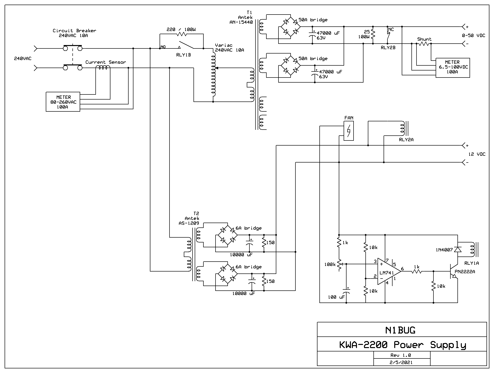
The power supply is about as simple (and efficient) as you can get, a few luxuries notwithstanding. It is unregulated, consisting of a variac, transformer, two bridge rectifiers and two large filter capacitors. It can provide 0 to 50 volts for the FET drains. The power transformer has two secondaries. Each has its own rectifier and filter capacitor. The two are combined at the output terminals of the supply. A small fan is used to blow air across the bridge rectifiers to aid in cooling. Because the filter capacitors are large and the transformer resistance is low, a soft start circuit is used to prevent inrush current problems. There is a separate transformer with a similar configuration to supply 12 volts to the amplifier driver circuits. The 12 volt supply also controls the soft start by means of a comparator which closes a relay to short out a resistor in the AC input to the variac after a short (adjustable) delay.
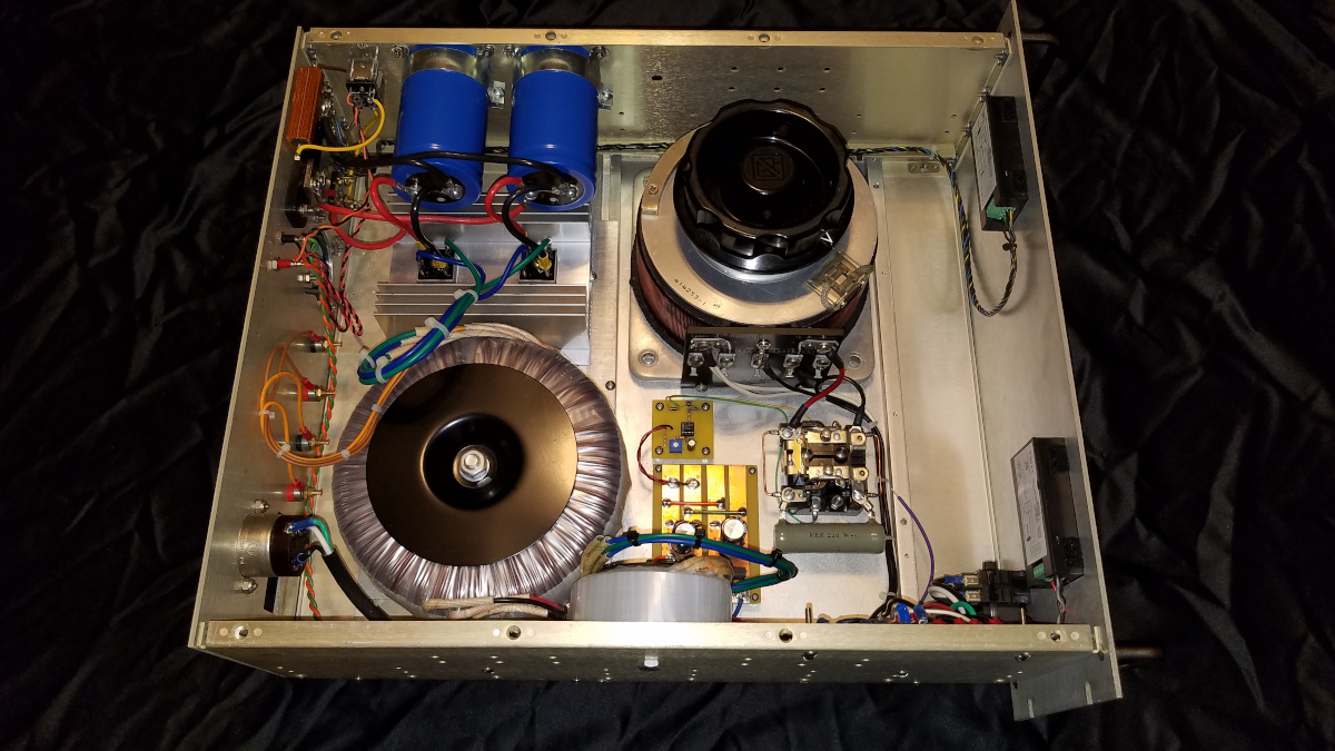
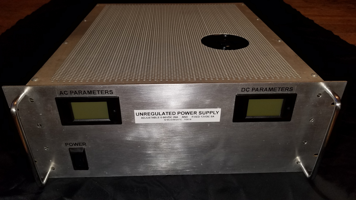
Schematic of the power supplyInternal view of the power supply. Space is limited and the variac would not fit on the front panel. It is accessed through a hole cut in the top cover of the supply.The power supply with top cover in place
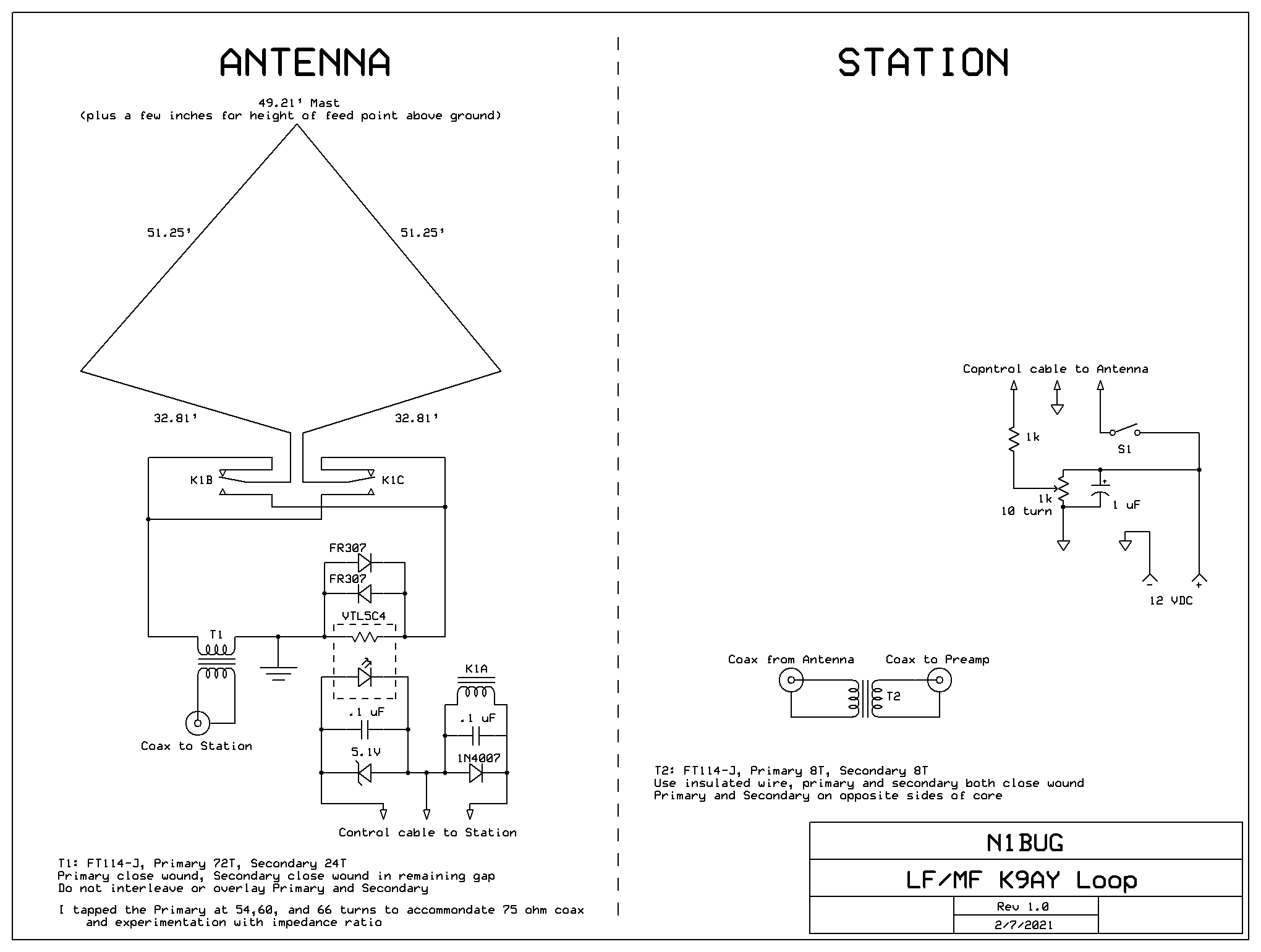
During the late summer and autumn of 2020 I built a K9AY loop, hoping it would help me hear DX on 2200 meters. Computer modeling suggested the minimum size for good front to back ratio and overall pattern would be twice the size of the original 160/80 meter K9AY loop design. This required a 50 foot mast. I chose to use a fiberglass mast to ensure there would be no interaction with the antenna. Since the “gain” of this antenna at 137 kHz is -55 dB, I was worried about common mode noise ingress. In an effort to minimize any such problems, transformer coupling was used at both ends of the coaxial cable feeding the antenna.
Having limited space I was not sure how successful this project would be. The K9AY would have to be located within 50 feet of my 2200 meter transmitting antenna, over the 160/630/2200 meter radial field, no more than 50 feet from one of the towers and just a bit over 100 feet from the other. That is not an ideal environment for a small directional receiving antenna!
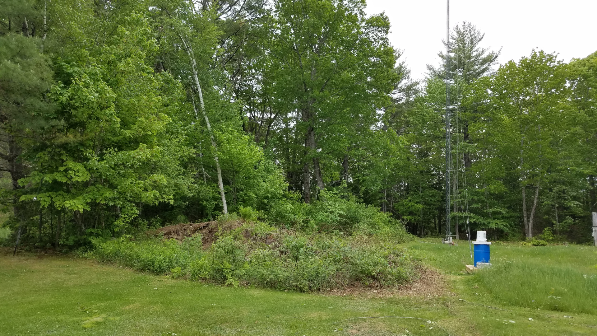
The best location, considering other antennas, seemed to be atop a small mound in the back yard. I immediately had misgivings about that, since I knew the origin of that mound. It was what was left after the lawn area was flattened with a bulldozer about 45 years ago. At the time there was an automobile junk yard next door, spilling over onto this property which was owned by the same party. I had no idea what I might find when I tried to dig a hole to put in concrete for the mast footing! In the first several inches, I encountered several strands of old barbed wire. Lovely! Next was a power steering pump and a water pump. At about the two foot level the real challenge presented itself: a buried concrete slab several inches thick, obscuring about two thirds of my hole area, and tilted at a 30 degree angle with respect to horizontal. Oh, great! It took hours of beating on that slab with a heavy steel bar to break it up and continue excavation. Digging a four foot deep hole 18 inches in diameter with nothing more than a spade is always fun, but I got the job done. It has been suggested on several occasions that I am “determined”. I think that is a nice way of calling me stubborn! But it fits.
Base of the K9AY loop mast (coax and control cable not yet installed)
When the antenna became operational, front to back was no better than 3 to 6 dB. Some quick experimentation showed that de-resonating the 2200 meter transmitting antenna improved the situation greatly. With that change I could often see 15 dB front to back but not always. Several methods for de-resonating were tried, but it turns out simply disconnecting the bottom of the loading coil/variometer from the secondary of the toroidal impedance matching transformer is as effective as any other method. I modified my station so that I could do that from the operating position and even have the antenna automatically resonated while transmitting and de-resonated while receiving.
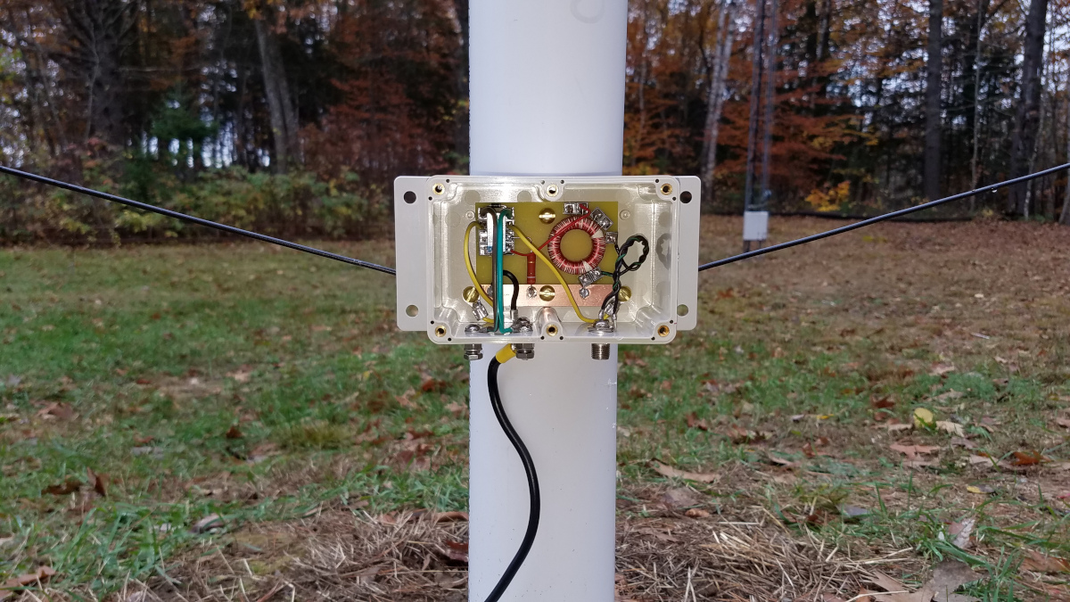
The original K9AY feed box with fixed terminating resistor (before installing coax and control cable)
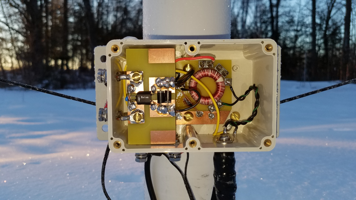
Over several weeks it became apparent the antenna’s performance was not stable. The pattern seemed to improve and worsen with environmental factors such as temperature and snow cover. Several other K9AY loop users suggested improving my ground system might help stabilize it but with snow already on the ground I decided that would not be practical until spring. I decided to modify the K9AY to use a vactrol instead of a fixed resistor for the termination. A vactrol is essentially a voltage variable resistor consisting of a LED and a photocell in a small four lead package. I obtained a VTL5C4 vactrol made by Xvive and installed it on the K9AY. Additional control conductors were run to the antenna so I could control the termination resistance remotely from the operating position. This change has thus far allowed achieving at least 17 dB front to back using sky wave signals as a reference on any given night. There have been times when I see more than 30 dB front to back on DX signals. I have no explanation for that, since the computer model suggested a maximum of 17.5 dB. Front to back often undergoes short term changes which I suspect are due to changing vertical arrival angle of signals, possibly with some contribution from skew path signals if that phenomenon exists on 2200 meters. Skew path is common on 160 meters. Termination resistance typically requires adjustment with major temperature changes and after significant snowfall events.
Modified K9AY loop box with vactrol for variable termination resistance
So, with those changes made, how does it work? Better than expected! I have been comparing antennas by listening simultaneously on both using identical receivers feeding identical sound interfaces on the same computer. I am using six instances of WSJT-X monitoring three modes: WSPR2, FST4W-120, and FST4W-1800. SNR as reported by WSJT-X is recorded for every signal received and each antenna it is received with. From that data, the following results have been extracted and calculated. The method is not perfect as there is uncertainty in the reported SNR, especially with weak signals near the decoding threshold. However it is the most practical method to get a reasonable comparison.
Before getting into the results, I should point out that having the new directional antenna has confirmed something I already suspected: I have more man made noise to the southwest/west than to the northeast/east. This means I get a bigger advantage from the K9AY loop when listening to signals from the northeast, which puts many of my local noise sources off the back. Any advantage when listening southwest is largely nullified by the fact that my local noise mostly comes from that direction. During the day, when atmospheric noise is not a factor, my noise floor increases between 2 and 5 dB in the southwest direction compared to northeast. In addition to this increase in the overall noise floor, a number of “interference lines” and some narrow smears can be seen.
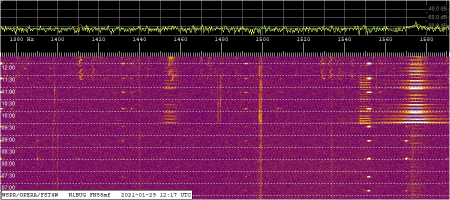
The WSPR/FST4W band segment. Northeast prior to 0930Z, southwest thereafter. Note more interference lines and squiggles southwest and the appearance of WB5MMB (1550 Hz) and WH2XND (1575 Hz) WSPR signals.The WSPR/FST4W band segment, Northeast prior to 0930Z, southwest thereafter. Note the huge increase in WH2XND’s WSPR signal at 1575 Hz.
Results from the night of 22/23 January, 2021: With the K9AY loop listening northeast, a total of 35 transmissions from European stations were received. Of those, 21 were decoded only on the K9AY loop, while 14 were decoded both on the K9AY and the LNV. Of the latter 14, signal to noise ratio was always better on the K9AY, the improvement ranging between 3 and 7 dB for an average of 4.3 dB. While listening southwest, a total of 47 transmissions from stations in that general direction were received. Of those, 45 were decoded on both antennas with an average advantage of 0.3 dB to the K9AY. One transmission was decoded only using the LNV and one using only the K9AY.
Results from the night of 23/24 January, 2021: Listening northeast, a total of 56 transmissions from European stations were decoded; 25 only on the K9AY and 31 on both antennas. Of the 31, S/N ranged from 2 to 7 dB better on the K9AY for an average of 4.0 dB. Listening southwest, a total of 66 transmissions were received from stations in that direction; 62 on both antennas with an average advantage of 0.2 dB to the K9AY, 3 only on the LNV and 1 only on the K9AY.
Results from the night of 24/25 January, 2021: Listening northeast, a total of 89 transmissions from European stations were decoded, 45 only on the K9AY and 44 on both antennas. Of the 44, S/N ranged from 1 to 11 dB better on the K9AY for an average of 5.5 dB. The k9AY gained greater advantage later in the period. This may have been due in part to increasing static from storms over the central U.S. Listening southwest, a total of 12 transmissions were received from stations in that direction. All were decoded on both antennas with an average advantage of 0.3 dB to the K9AY.
Results from the night of 25/26 January, 2021: Listening northeast, a total of 17 transmissions from European stations were decoded; 7 only on the K9AY and 10 on both antennas. Of the 10, S/N ranged from 2 to 6 dB better on the K9AY for an average of 4.0 dB. Listening southwest, just one transmission was decoded, and only on the K9AY. However, it was a good one, AX4YB (VK4YB with a special prefix for Australia Day).
Results from the night of 26/27 January, 2021: Listening northeast, a total of 6 transmissions from European stations were decoded; 1 only on the K9AY and 5 on both antennas. Of the 5, S/N ranged from 1 to 5 dB better on the K9AY for an average of 3.6 dB. Listening southwest, a total of 18 transmissions were received from stations in that direction; all were received with both antennas with an average advantage of 0.3 dB to the LNV.
Results from the night of 27/28 January, 2021: Listening northeast, a total of 27 transmissions from European stations were decoded; 6 only on the K9AY and 21 on both antennas. Of the 21, S/N ranged from 2 to 6 dB better on the K9AY for an average of 2.8 dB. Listening southwest, a total of 49 transmissions were received from stations in that direction; 45 on both antennas with an average advantage of 0.4 dB to the K9AY, 1 only on the LNV and 3 only on the K9AY.
Results from the night of 28/29 January, 2021: On this night my local noise was somewhat lower than in previous nights, which may have contributed to slightly different results. Listening northeast, a total of 24 transmissions from European stations were decoded; 7 only on the K9AY, 1 only on the LNV and 16 on both antennas. Of the 16, S/N ranged from 0 to 4 dB better on the K9AY for an average of 2.3 dB. Listening southwest, a total of 47 transmissions were received from stations in that direction; 44 on both antennas with an average advantage of 0.6 dB to the K9AY, 3 only on the K9AY. VK4YB was received twice on each antenna, the first time with a 2 dB advantage to the K9AY and the second time equal on both antennas.
Results from the night of 29/30 January, 2021: Northeast there were a total of 21 transmissions from Europe decoded. Of the 10 captured on both antennas, S/N ranged from 2 to 4 dB better on the K9AY for an average of 2.7 dB. Southwest had a total of 38. 37 were received on both antennas with an average advantage of 0.1 dB to the K9AY. One was decoded only with the LNV.
Results from the night of 30/31 January: Northeast had a total of 8, four being heard with both antennas with S/N favoring the K9AY between 2 and 3 dB with an average of 2.7 dB. Southwest there were 40 in total, 36 being heard on both antennas with an average advantage of 0.4 dB to the K9AY. Two were heard only with the LNV and two only with the K9AY.
These results should be considered in the context of “what can I receive with one antenna that I cannot with the other” rather than “how many dB better is one antenna than the other”. Why? Because of the noise blanker settings I am using for the FST4W modes in WSJT-X. The way I have it set, it will first try to decode without any noise blanking. If that succeeds it will stop there. If not it will next try with a noise blanker setting of 5%. If that succeeds it will stop there. If not it will in turn try 10, 15, and 20% but it will stop at any point if a successful decode is obtained. What this means is that if on a given antenna it is able to decode a signal without using the noise blanker or with a low noise blanker level, it makes no attempt to see if it could get a better signal to noise ratio using more noise blanking. But when decoding on the “weaker” antenna it might get one or more levels deeper into noise blanking before obtaining a decode. This can have the effect of reducing the reported difference in S/N between the two antennas. During these tests I saw many cases where it decoded almost immediately on the K9AY but took longer on the LNV. This suggests on the LNV it was requiring more noise blanking to succeed, and that some of the decodes on that antenna might not have happened at all if I used no noise blanking or only one fixed setting. So if anything, the advantage of the K9AY is likely understated in these tests.
While not formally summarized in the above results, I have been paying attention to apparent front to back when receiving signals off the back of the K9AY. I say apparent because I am not switching the K9AY to the other direction but instead comparing the S/N ratio on the LNV to that of the K9AY. One some nights, apparent front to back is typically 10 to 15 dB with some values in the single digits. Other nights it ranges from single or low double digits to 24 dB or more. I suspect at times it is even more. For example I received a transmission from WH2XND at 0 dB S/N on the LNV but it did not decode at all off the back of the K9AY and could not be seen on any of my waterfalls, fast or slow! That would suggest something on the order of 30 dB difference between the two antennas.
The bottom line is that I am receiving a lot more European DX thanks to the K9AY loop. This antenna is well worth the work and expense that went into it.
Intermittent listening on 630 meters prior to the vactrol modification suggested an even bigger improvement northeast over the LNV on that band, though no formal comparison was made to to lack of a second receiver. On this band there may have been more advantage to the K9AY in the southwest direction but it was hard to tell with just one receiver.
In early 2020 I began phasing out much of the first generation LF equipment and building replacements. My LF operating interests focus largely on DX. As I have learned more about all of this, it became obvious I needed some upgrades. This is the second in a series of posts about new equipment for our lowest frequency amateur radio allocation.
Like the first generation receiver, the transmitting downconverter did not have adequate frequency stability for slow modes on LF. I also wanted something that didn’t tie up my only HF rig when operating on 2200 meters. After reviewing several designs for phasing exciters I settled on a design by W1VD. I built mine Manhattan style using MEPads and MESquares from QRPme.
The MPS6650 and MPS6652 transistors used by W1VD are no longer available. I successfully substituted BC33716BU and BC32716BU devices but I have not been able to achieve the stated +20 dBm output. Mine will only make +16 dBm before the output waveform becomes distorted. This works OK with my amplifier but is a subject I would like to revisit at a later date.
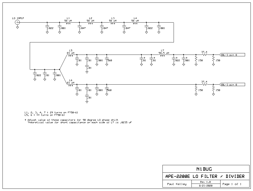
Initially I encountered some difficulty getting good carrier and opposite sideband suppression. I traced the problem to the LO signal to the two mixers not being 90 degrees out of phase. I built several variants of the quadrature hybrid but I could not get accurate 90 degree phase shift or equal amplitude. Trying some alternate approaches, I achieved success using a Wilkinson divider and phase shift network. Some cut and try adjustment of two capacitor values was needed but in the end I achieved accurate 90 degree phase shift with similar amplitude on both ports. I used 6 dB resistive attenuators on the two LO signals before feeding the mixers. The two outputs from this circuit go directly to pin 8 on the two SBL-3 mixers in the exciter. The 6 dB pad, C1, C2, T1, C3, C4 and the associated 49.9 ohm resistor shown in the W1VD exciter schematic were omitted. With this arrangement I was able to achieve better than 55 dB carrier and opposite sideband rejection after careful adjustment of the level and phase balance trimmers in the exciter. If you build this and find it is operating on the wrong sideband, reverse the LO inputs to the mixers. If you look closely at the blue and orange wires coming off the LO divider and phase shift board, you will see they cross over each other on the way to the mixers on the main board below. Mine had ended up being on lower sideband the first time around! One other change should be made to the phasing exciter if you will be operating it into a 50 ohm load: omit the 49.9 ohm resistor in series with the output. The 1 uF capacitor should connect directly to the junction of the two 5.1 ohm resistors.
LO filter and Wilkinson divider with phase shift network
I am using the same Leo Bodnar GPS Clock that supplies 408000 Hz to the new receiver. It supplies 136000 Hz square wave to the exciter, which I low pass filter before the divider.
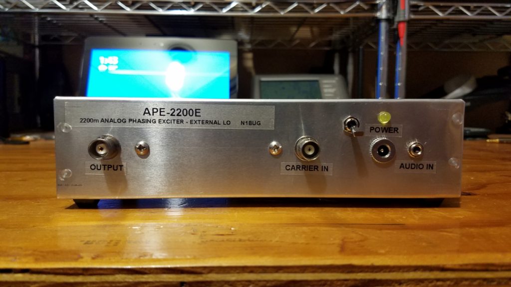
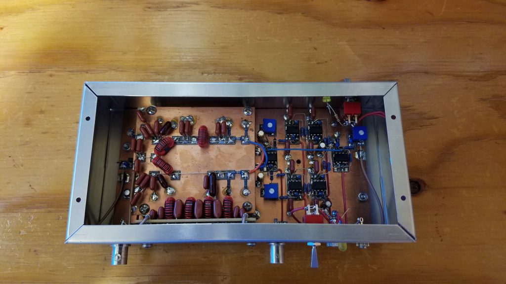
Internal view of the completed phasing exciter. Originally mounted to the side of a rack in my main shack, I had placed the power switch and LED on the side opposite the connectors. When I subsequently relocated LF operations to the workshop, that was not convenient so I added another switch and LED near the DC power connector.
I have many hours of operation with this exciter in various modes. It has performed well. One thing this exciter does not like is magnetic fields which can couple 60 Hz energy to the audio circuits. Don’t put it too close to a linear power supply!
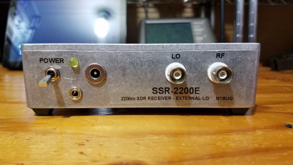
The SSR-2200E, my second generation LF receiver based on the SoftRock Lite II
In early 2020 I began phasing out much of the first generation LF equipment and building replacements. My LF operating interests focus largely on DX. As I have learned more about all of this, it became obvious I needed some upgrades. This is the first in a series of posts about new equipment for our lowest frequency amateur radio allocation.
After using the original modified SoftRock Lite II receiver for three years, it was time to move on. That first receiver served me very well. With it I was able to make three trans-Atlantic QSOs, and heard a lot of DX on various modes. In the end, however, I wasn’t satisfied with the frequency stability of the crystal oscillator, which was about 1 ppm, or a little less than 0.15 Hz drift on 2200 meters. That may seem completely insignificant to the HF, VHF or microwave operator but for the most serious DX pursuits on LF it not sufficient. With the one watt EIRP legal power limit, propagation and high noise levels at 137 kHz we need very slow modes to succeed over great distances. As a general concept, the slower the mode the greater the frequency stability needed. Legacy modes include QRSS (extremely slow CW meant to be read visually from a waterfall) and its derivatives like DFCW. Readers may recall my first DX QSO with 2E0ILY used DFCW60, meaning that each “dit” or “dah” takes 60 seconds to send! Drift of 0.15 Hz is clearly visible at that speed and can lead to difficulty “reading” signals at even slower speeds. Today we have various slow digital modes for beaconing and QSOs. At the extreme, EbNaut requires transmitter and receiver drift be no more than a few tens of microHertz! Others are more tolerant but current evolution suggests one should strive to stay within 0.01 Hz or better during any 30 minute period if DX is of prime interest.
During those first three years I had tried various receiver, filter and preamp configurations. I now know what is needed with the SoftRock and my available antennas. I wanted to combine the filter, preamp and receiver into one box but I wanted to use a GPS referenced local oscillator for stability. In the end I settled on a design which puts all but the local oscillator into one box. The LO is a separate Leo Bodnar GPS Clock which supplies 408 kHz for the receiver (divided by four in the SoftRock quadrature LO generator) and 136 kHz for a 2200m phasing exciter.
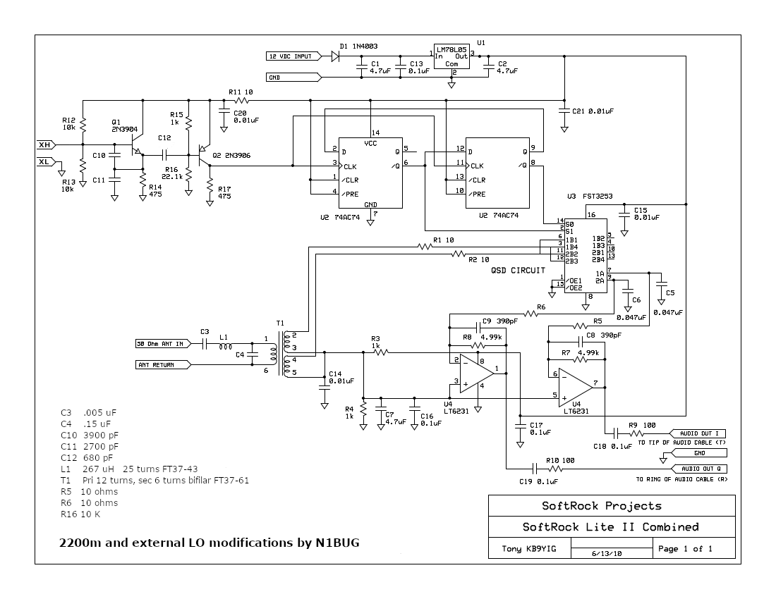
The major building block for the receiver is a SoftRock Lite II kit from Five Dash. A few modifications need to be made for 2200m operation. The schematic shows the values for parts that need to change for operation on this band (C3, C4, C10, C11, C12, L1, T1, R5, R6, R16), as well as the removal of the crystal and external LO connections in its former place. The capacitors can be ceramic. I recommend mounting the SoftRock Lite II board with the insulating hardware that comes with it. Ideally one wants everything isolated from the metal box except for the shield of the audio cable connector. To maintain that one ground point I run the receiver either on a battery or an isolated wall wart.
Schematic of the modified SoftRock Lite II
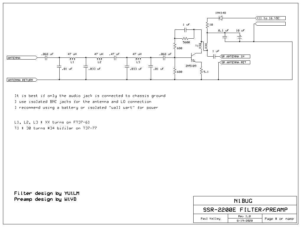
For the front end stages I have married a filter design by YU1LM and a preamp design by W1VD. The filter provides a bandpass response to keep out of band signals from overwhelming the receiver, while the preamp provides about 20 dB gain which is needed with many small receiving antennas on LF. You want enough gain in the front end and receiver so that the noise floor comes up at least 10 dB when you connect the antenna. If this seems a little different from conventional advice, consider that we are dealing with extremely weak signals where even fractions of a dB can make a difference. If we want to keep the signal to noise ratio from being degraded a meaningful amount, we need that much gain to be sure the SoftRock and sound card noise floor don’t degrade S/N of the system. With the exception of the 10 uF electrolytic, all capacitors are ceramic types.
Schematic of the front end filter and preamp
Next I needed a suitably stable local oscillator. We need a final LO frequency that is close enough to the 2200 meter band to allow tuning it with whatever sound card will be used. If the sound card sample rate is 96 kHz, we need to be within 48 kHz of the receiving frequency. I recommend staying a few kHz less than that due to the way anti-aliasing filters in sound cards work. This means we want our LO to be between about 96 kHz and 178 kHz in practice, preferably avoiding putting it “in band”. The LO frequency is divided by four in the SoftRock quadrature generator circuit. This means we need to inject a frequency four times higher into the receiver. Anything between 384 and 712 kHz will work. I was already using one of the two outputs from the GPS Clock to provide 136000 Hz LO to my phasing exciter. Available frequencies for the second output are somewhat limited and tied to the first frequency but in this case 408000 Hz is one of the options, and it is perfect. That puts our final LO at 102 kHz, comfortably within range, yet far enough removed from the band of interest to put the image frequency around 67 kHz, well down the slope of the receiver front end bandpass filter. Perfect!
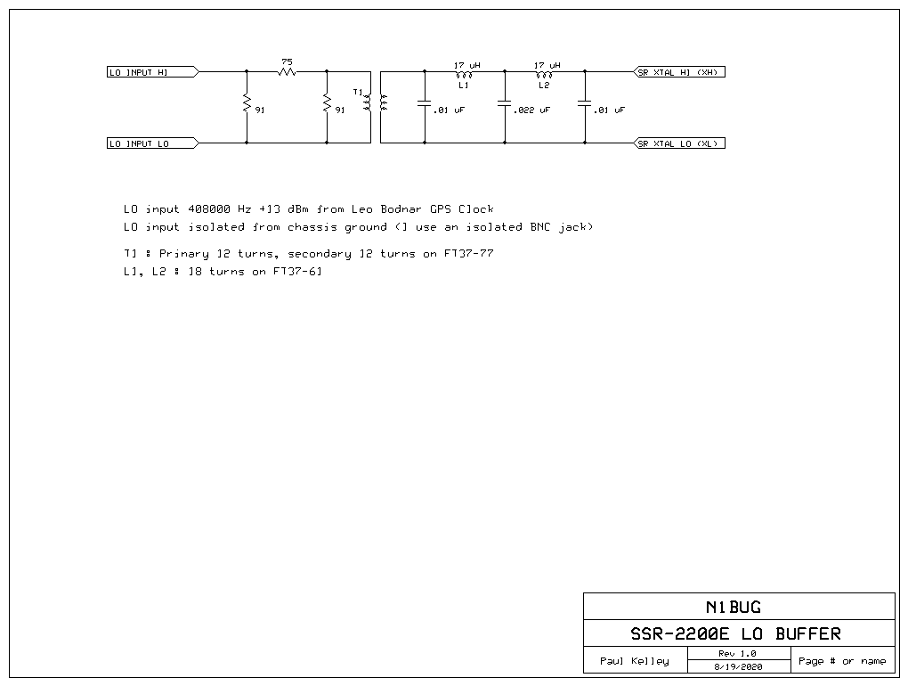
First I tried injecting the 408 kHz square wave directly into the SoftRock. It worked but I didn’t have a good feeling about it. For one thing, that meant that the SoftRock and GPS clock grounds were connected, a situation which I was trying to avoid in case of ground loops and noise getting into the system. The GPS Clock also didn’t like the impedance, causing it to put out not only the harmonic rich square wave but also a significant amount of HF energy as ringing due to impedance mismatch. I tried using a transformer (for ground isolation) and low pass filter to clean up harmonics but this made the GPS Clock even less happy with a lot of ringing due to reflections. Since I had signal to spare I solved this, albeit somewhat crudely, but inserting a 10 dB attenuator between the GPS Clock and transformer. This gave a nice clean sine wave at sufficient level into the SoftRock LO circuit. I don’t claim this design to be elegant or perfect, but I do claim it works well for me. I used film capacitors in the filter because I had them on hand, but ceramic should be quite acceptable.
Schematic for the LO isolation and filter circuit
This new receiver has been in operation for several months. Sensitivity and gain is more than adequate for use with my LNV antenna. Frequency stability is now determined almost entirely by sound card sample rate drift and is on the order of 0.01 Hz over several hours. This is sufficient for all but EbNaut, where the sound card sample rate requires continuous monitoring and correction. I have not conquered that yet.
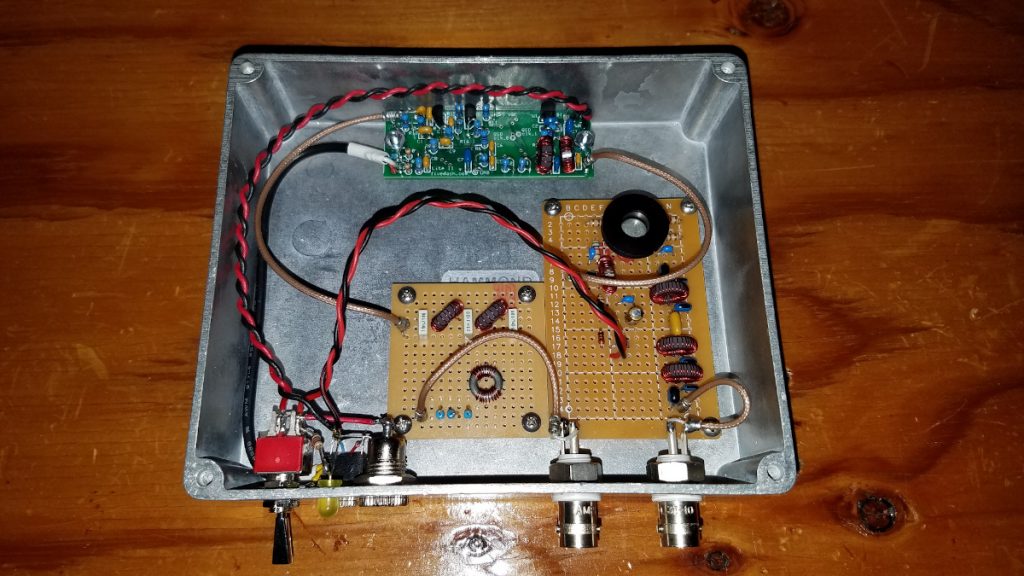
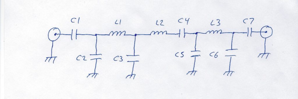
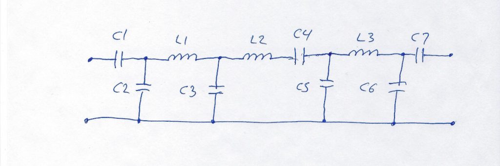
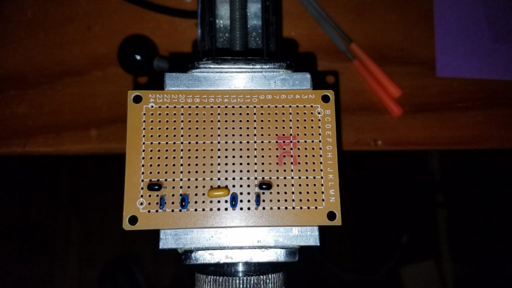
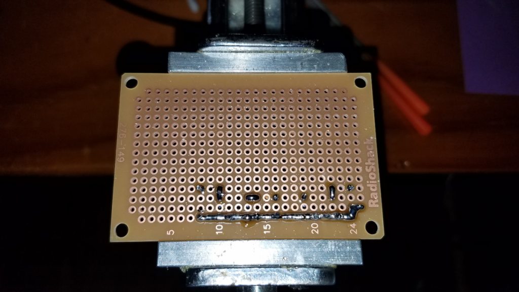
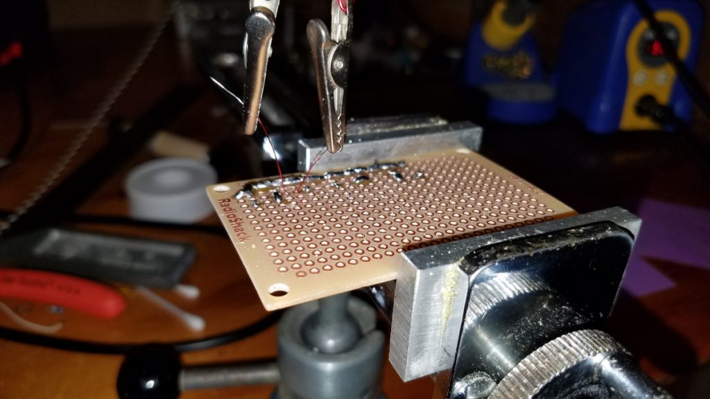
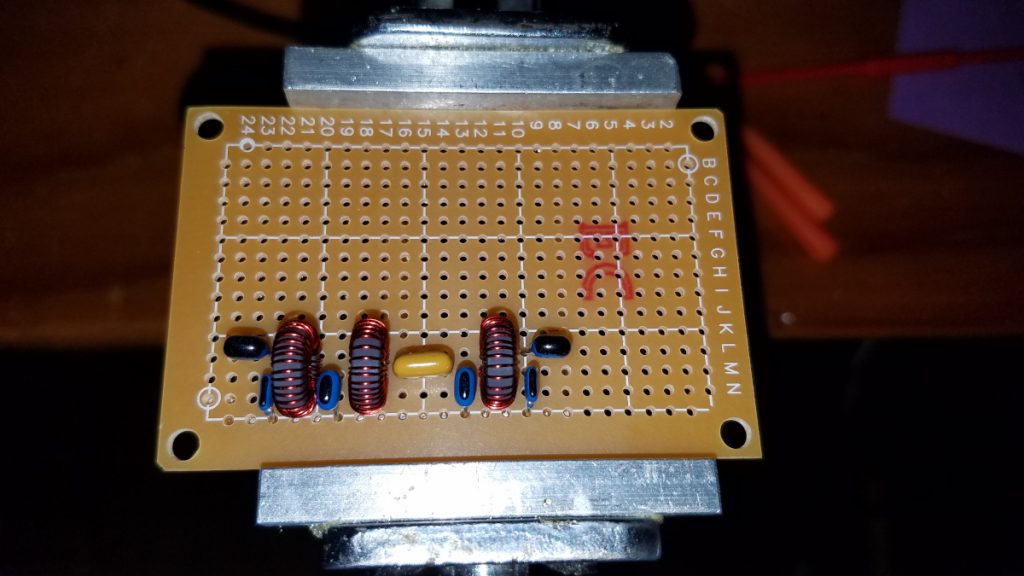
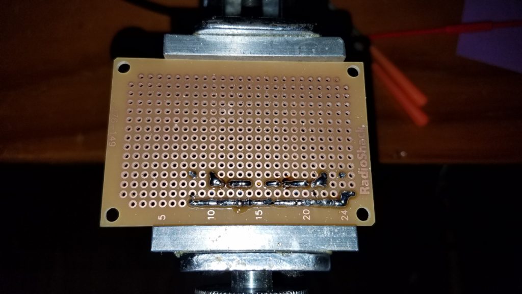
Occasionally I get asked how I go about building circuits on proto boards. This post describes how I built a low frequency band pass filter.
For some circuits, the layout will not be so easy, but for simple filters like this I have a method I almost always follow. Let’s start by looking at the schematic for the filter I will be building.
Original schematic diagram for the filter
Now let’s think about that for a moment. We see one side of four capacitors (C2, C3, C5, C6) is connected to circuit ground. Also the shell of the input and output coaxial connectors are connected to circuit ground. If all of those points are connected to ground, then they are all connected to each other. To make this clearer, we can redraw the schematic as follows.
Schematic redrawn to make it clearer how all “ground” points are connected to each other
I like to lay out my parts on the board so they physically resemble the schematic representation. If you think of the top of the schematic as north, bottom south, left west, right east as if it were a map (it is a circuit map!), then we can think in terms of components oriented along a north-south line or east-west line. C1, for example, has one of its leads on the west and another east. C2 is a north-south oriented part. For a filter such as this, I start by laying out all the capacitors on the proto board in much the same way they are represented in the schematic, making sure to leave spaces to fit in the inductors later on. As I put each capacitor onto the board, I spread its leads slightly on the back side so the parts won’t fall off the board when I turn it over for soldering. They don’t have to be spread much.
Proto board with capacitors laid out according to the schematic representation, leaving gaps for the inductors
I then flip the board over and just solder each capacitor lead to the pad around it. If using a temperature controlled iron, I suggest about 650F for soldering on these boards. Then I clip off excess lead length. Next, with the the help of the schematic I identify any capacitors that are connected to their neighboring capacitor and make those solder connections on my board. I’ve developed a method of doing this using a solder blob but many builders will prefer to use a short piece of wire soldered across the pads as a jumper. Another method is to fully bend over one or more leads before soldering to the board, so that the component lead itself becomes the jumper. That method is easy, but if it becomes necessary to remove a part later, it can complicate matters. Finally at this stage I connect all the grounds together in a row, just as they are shown in the modified schematic. Again, using solder blobs I have developed a technique to build such circuit paths entirely of solder but a buss wire soldered along the board will probably be easier for most builders. With regard to my solder blobs and building solder rows, it is much easier if the iron is not too hot. 650F is on the warm side. 600 or even a little lower can make it easier to bridge blobs without them separating from neighboring blobs while doing it. This is second nature to me now, but it took a while to develop this skill. It involves getting a decent size blob of molten solder on the tip and then placing it into the gap where you want to form a bridge. Putting the iron in there and then trying to add the solder does not work!
The back side of the board after soldering capacitors and forming the ground path along the bottom edge
The next step is installing the inductors. In this case, they are toroids. It may appear that the toroid itself is oriented along a north-south line while the schematic shows them east-west, but if you think of how the two leads come off the sides of the toroid, the leads are oriented east-west as are the connection points on the schematic. I hate having my toroids end up loose and wobbly on the board, and spreading leads doesn’t keep them tight against the board while soldering when small gauge wire is used. I have developed a method to help hold those little devils in place and keep them snug against the board while I solder them. It involves clip leads on the end of strings which loop up and over an overhead support with weights on the other end. This puts upward tension on the leads, pulling the toroid snug against the board.
Clips of toroid support and tension system clipped to inductor leadsWide shot of the toroid support and tension system. I didn’t bother tidying up the bench before taking these photos!
A few words about soldering of the enameled wire may be in order. Life is too short for scraping or sanding the enamel off these very fine wires. I use wire with enamel that can be heat stripped. The heat of a hot soldering iron (I recommend 750F) along with fresh solder and perhaps a bit of liquid flux on the wire (if it is available) will burn the enamel off. The problem is it takes a few seconds and that much heat can cause the copper rings to come off the proto board! I hold the soldering tip against the wire about 1/16 inch above the board, being careful not t let it touch the board. It is necessary to apply a bit of solder to get the heat transfer working well enough but with a bit of practice the insulation can be burned off and the wire tinned without much difficulty. Dabbing a bit of flux (liquid or paste) on the wire before applying heat can be very helpful. If the wire is fluxed, usually just getting a small blob of solder on the hot tip and touching it to the wire for a couple of seconds will get the job done. I admit my first few attempts at this didn’t go so well but I got the hang of it after a bit of practice. Once the lead is properly tinned I can solder it to the pad on the board. At 750F this should be done quickly! Sometimes I lower the heat to 650F before soldering to the board. Once both leads are soldered to the board, I connect them to the adjacent components using my solder blob technique while the overhead support system is still keeping tension on the wires. Once all the soldering around these leads is finished, the alligator clips can be removed and the inductor leads cut short.
In this simple filter build that’s it except for connecting it to the outside world in whatever manner is appropriate for the project at hand.
Top view of completed filterBottom view of completed filter