Occasionally I get asked how I go about building circuits on proto boards. This post describes how I built a low frequency band pass filter.
For some circuits, the layout will not be so easy, but for simple filters like this I have a method I almost always follow. Let’s start by looking at the schematic for the filter I will be building.
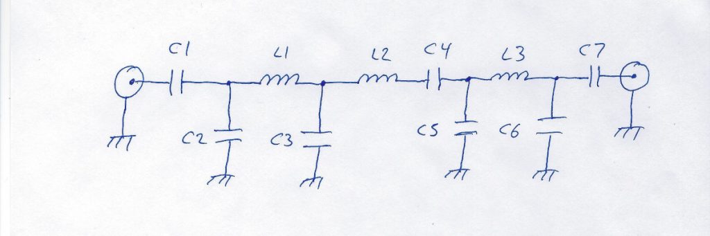
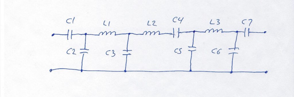
Now let’s think about that for a moment. We see one side of four capacitors (C2, C3, C5, C6) is connected to circuit ground. Also the shell of the input and output coaxial connectors are connected to circuit ground. If all of those points are connected to ground, then they are all connected to each other. To make this clearer, we can redraw the schematic as follows.
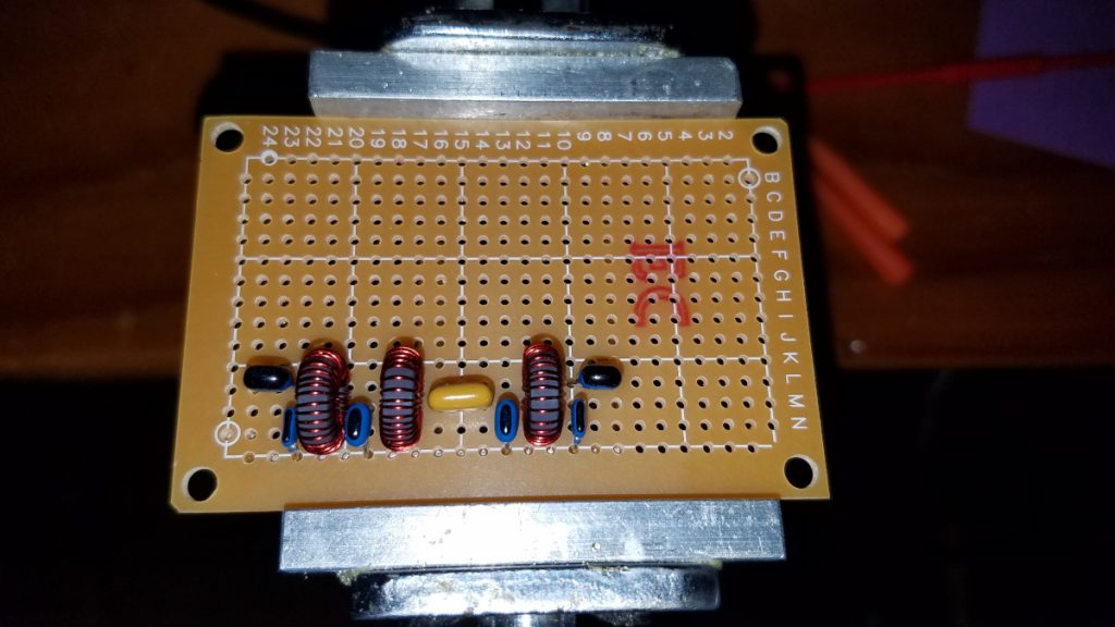
I like to lay out my parts on the board so they physically resemble the schematic representation. If you think of the top of the schematic as north, bottom south, left west, right east as if it were a map (it is a circuit map!), then we can think in terms of components oriented along a north-south line or east-west line. C1, for example, has one of its leads on the west and another east. C2 is a north-south oriented part. For a filter such as this, I start by laying out all the capacitors on the proto board in much the same way they are represented in the schematic, making sure to leave spaces to fit in the inductors later on. As I put each capacitor onto the board, I spread its leads slightly on the back side so the parts won’t fall off the board when I turn it over for soldering. They don’t have to be spread much.
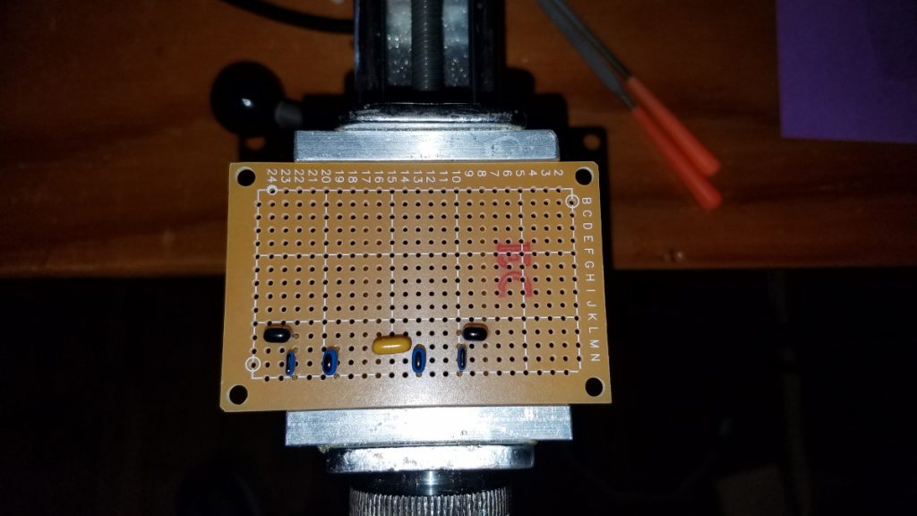
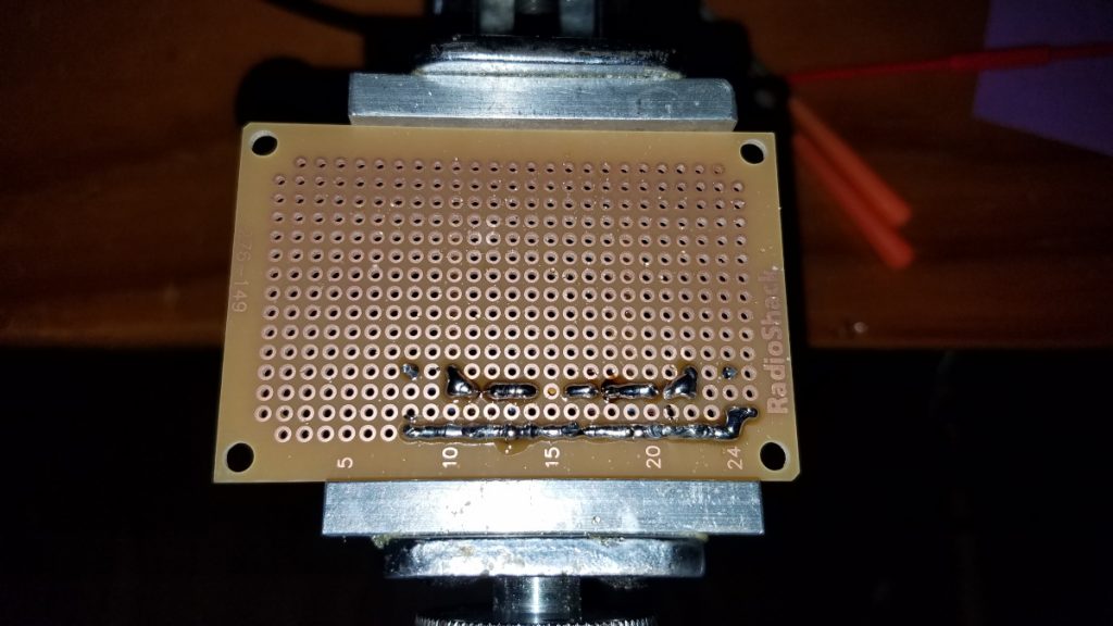
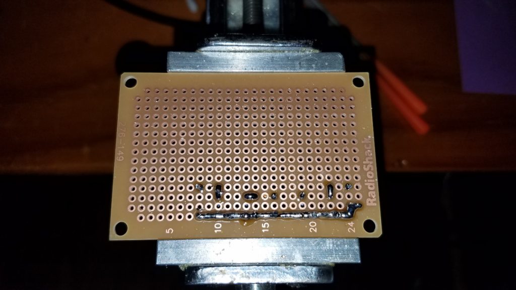
I then flip the board over and just solder each capacitor lead to the pad around it. If using a temperature controlled iron, I suggest about 650F for soldering on these boards. Then I clip off excess lead length. Next, with the the help of the schematic I identify any capacitors that are connected to their neighboring capacitor and make those solder connections on my board. I’ve developed a method of doing this using a solder blob but many builders will prefer to use a short piece of wire soldered across the pads as a jumper. Another method is to fully bend over one or more leads before soldering to the board, so that the component lead itself becomes the jumper. That method is easy, but if it becomes necessary to remove a part later, it can complicate matters. Finally at this stage I connect all the grounds together in a row, just as they are shown in the modified schematic. Again, using solder blobs I have developed a technique to build such circuit paths entirely of solder but a buss wire soldered along the board will probably be easier for most builders. With regard to my solder blobs and building solder rows, it is much easier if the iron is not too hot. 650F is on the warm side. 600 or even a little lower can make it easier to bridge blobs without them separating from neighboring blobs while doing it. This is second nature to me now, but it took a while to develop this skill. It involves getting a decent size blob of molten solder on the tip and then placing it into the gap where you want to form a bridge. Putting the iron in there and then trying to add the solder does not work!
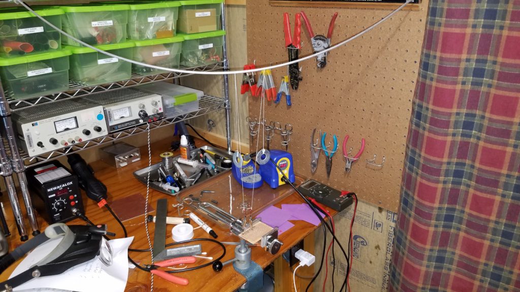
The next step is installing the inductors. In this case, they are toroids. It may appear that the toroid itself is oriented along a north-south line while the schematic shows them east-west, but if you think of how the two leads come off the sides of the toroid, the leads are oriented east-west as are the connection points on the schematic. I hate having my toroids end up loose and wobbly on the board, and spreading leads doesn’t keep them tight against the board while soldering when small gauge wire is used. I have developed a method to help hold those little devils in place and keep them snug against the board while I solder them. It involves clip leads on the end of strings which loop up and over an overhead support with weights on the other end. This puts upward tension on the leads, pulling the toroid snug against the board.
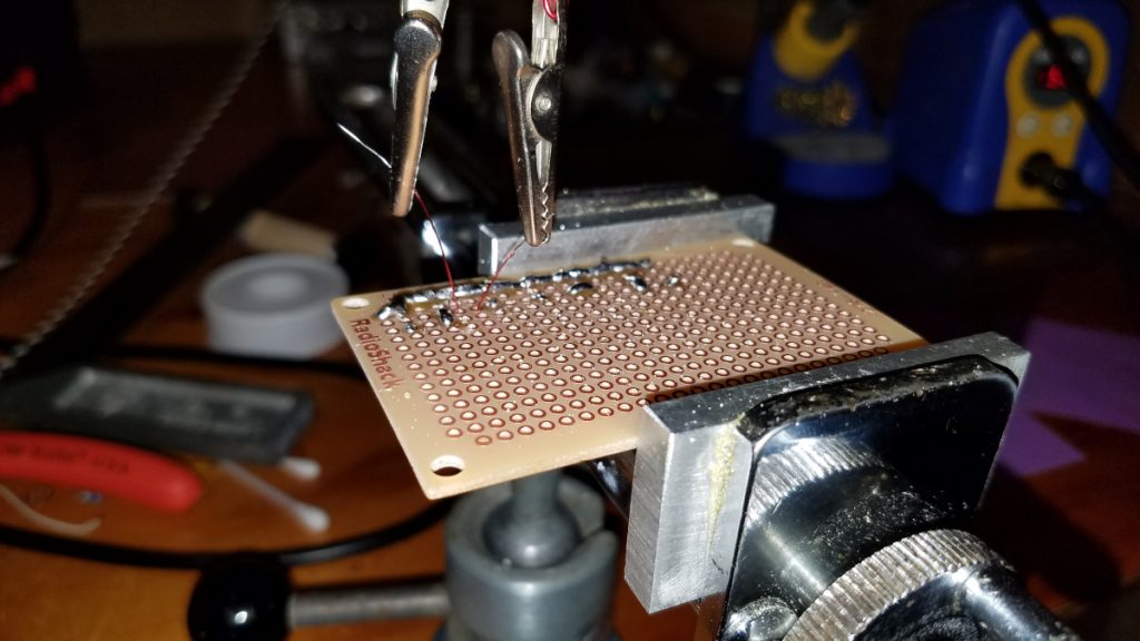
A few words about soldering of the enameled wire may be in order. Life is too short for scraping or sanding the enamel off these very fine wires. I use wire with enamel that can be heat stripped. The heat of a hot soldering iron (I recommend 750F) along with fresh solder and perhaps a bit of liquid flux on the wire (if it is available) will burn the enamel off. The problem is it takes a few seconds and that much heat can cause the copper rings to come off the proto board! I hold the soldering tip against the wire about 1/16 inch above the board, being careful not t let it touch the board. It is necessary to apply a bit of solder to get the heat transfer working well enough but with a bit of practice the insulation can be burned off and the wire tinned without much difficulty. Dabbing a bit of flux (liquid or paste) on the wire before applying heat can be very helpful. If the wire is fluxed, usually just getting a small blob of solder on the hot tip and touching it to the wire for a couple of seconds will get the job done. I admit my first few attempts at this didn’t go so well but I got the hang of it after a bit of practice. Once the lead is properly tinned I can solder it to the pad on the board. At 750F this should be done quickly! Sometimes I lower the heat to 650F before soldering to the board. Once both leads are soldered to the board, I connect them to the adjacent components using my solder blob technique while the overhead support system is still keeping tension on the wires. Once all the soldering around these leads is finished, the alligator clips can be removed and the inductor leads cut short.
In this simple filter build that’s it except for connecting it to the outside world in whatever manner is appropriate for the project at hand.