Category Archives: RFI

Experimenting with a K9AY loop on LF

50 foot mast supporting LF/MF K9AY loop

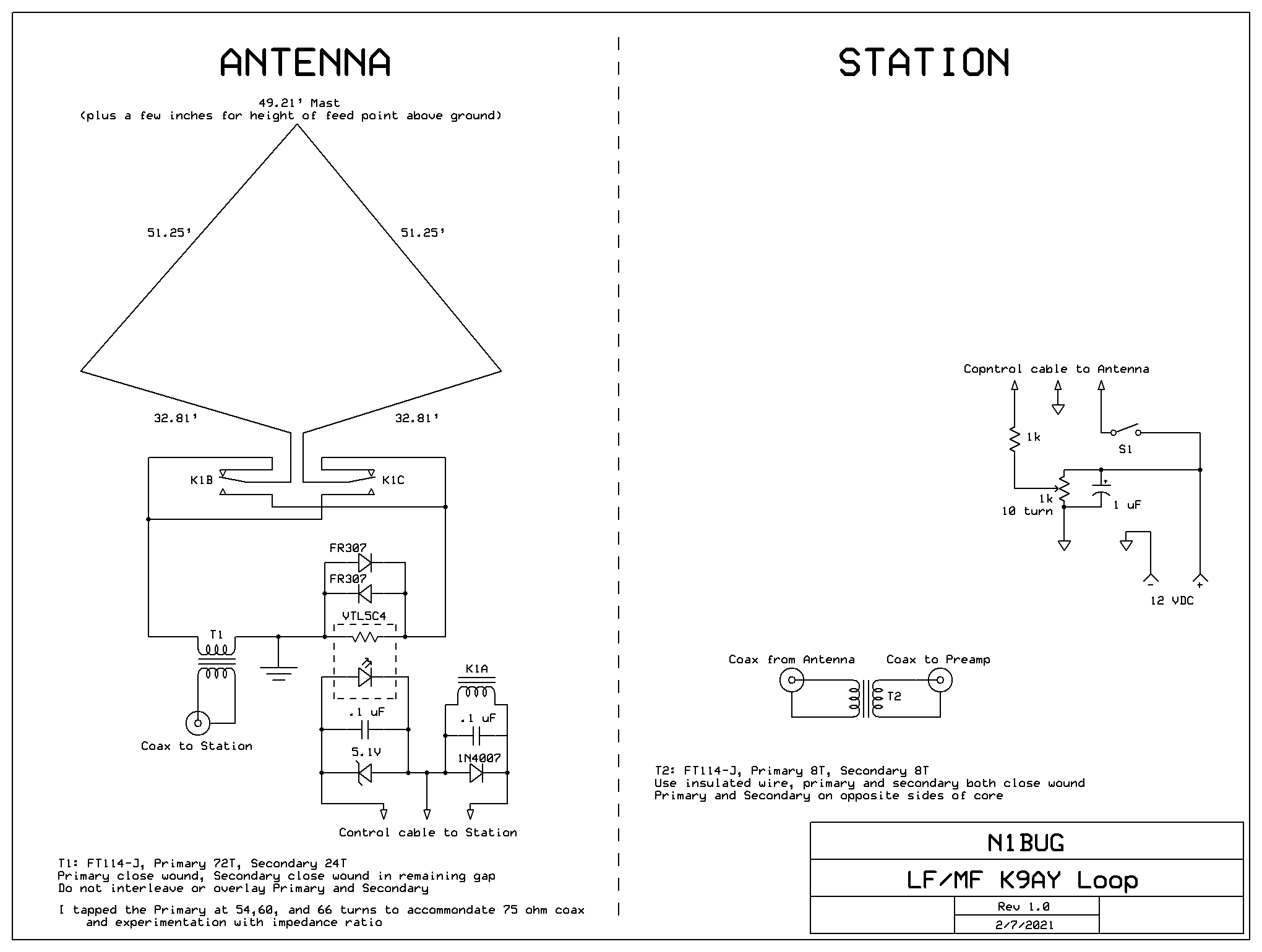
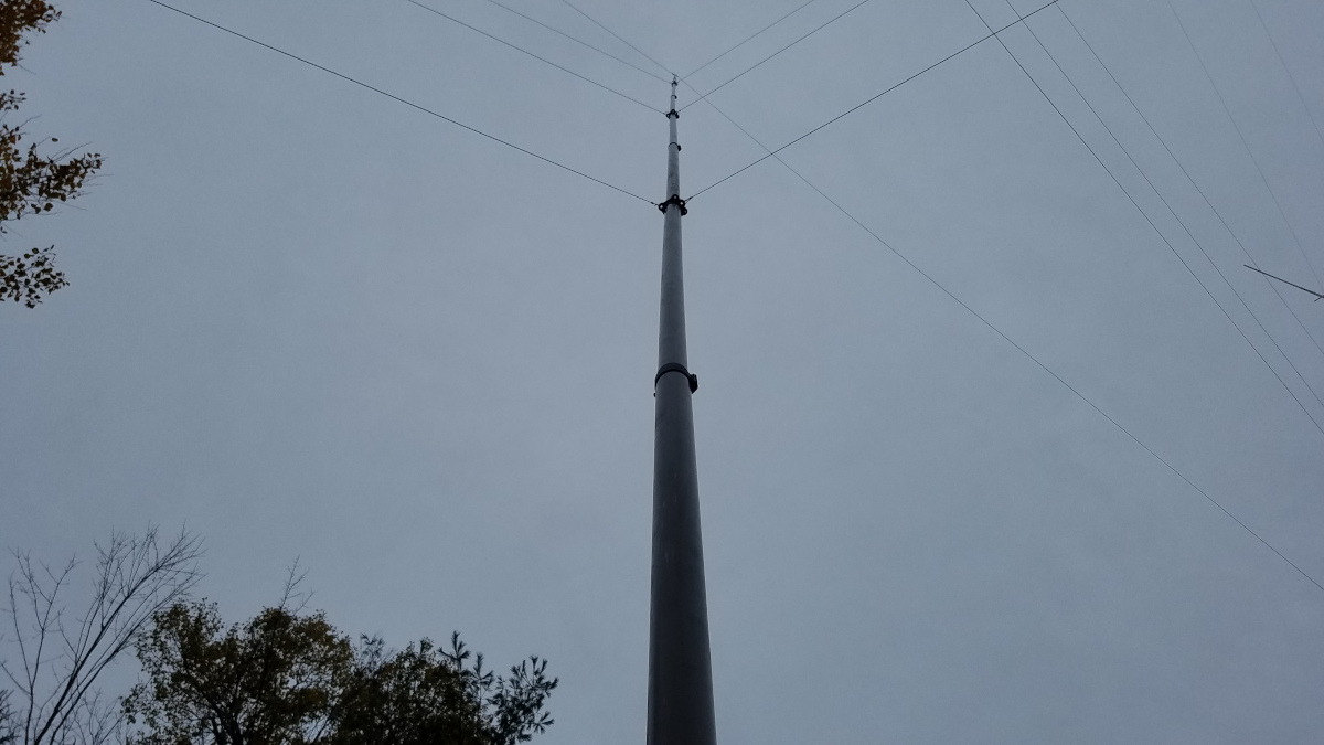
During the late summer and autumn of 2020 I built a K9AY loop, hoping it would help me hear DX on 2200 meters. Computer modeling suggested the minimum size for good front to back ratio and overall pattern would be twice the size of the original 160/80 meter K9AY loop design. This required a 50 foot mast. I chose to use a fiberglass mast to ensure there would be no interaction with the antenna. Since the “gain” of this antenna at 137 kHz is -55 dB, I was worried about common mode noise ingress. In an effort to minimize any such problems, transformer coupling was used at both ends of the coaxial cable feeding the antenna.

Having limited space I was not sure how successful this project would be. The K9AY would have to be located within 50 feet of my 2200 meter transmitting antenna, over the 160/630/2200 meter radial field, no more than 50 feet from one of the towers and just a bit over 100 feet from the other. That is not an ideal environment for a small directional receiving antenna!

The best location, considering other antennas, seemed to be atop a small mound in the back yard. I immediately had misgivings about that, since I knew the origin of that mound. It was what was left after the lawn area was flattened with a bulldozer about 45 years ago. At the time there was an automobile junk yard next door, spilling over onto this property which was owned by the same party. I had no idea what I might find when I tried to dig a hole to put in concrete for the mast footing! In the first several inches, I encountered several strands of old barbed wire. Lovely! Next was a power steering pump and a water pump. At about the two foot level the real challenge presented itself: a buried concrete slab several inches thick, obscuring about two thirds of my hole area, and tilted at a 30 degree angle with respect to horizontal. Oh, great! It took hours of beating on that slab with a heavy steel bar to break it up and continue excavation. Digging a four foot deep hole 18 inches in diameter with nothing more than a spade is always fun, but I got the job done. It has been suggested on several occasions that I am “determined”. I think that is a nice way of calling me stubborn! But it fits.

Base of the K9AY loop mast (coax and control cable not yet installed)

When the antenna became operational, front to back was no better than 3 to 6 dB. Some quick experimentation showed that de-resonating the 2200 meter transmitting antenna improved the situation greatly. With that change I could often see 15 dB front to back but not always. Several methods for de-resonating were tried, but it turns out simply disconnecting the bottom of the loading coil/variometer from the secondary of the toroidal impedance matching transformer is as effective as any other method. I modified my station so that I could do that from the operating position and even have the antenna automatically resonated while transmitting and de-resonated while receiving.

The original K9AY feed box with fixed terminating resistor (before installing coax and control cable)

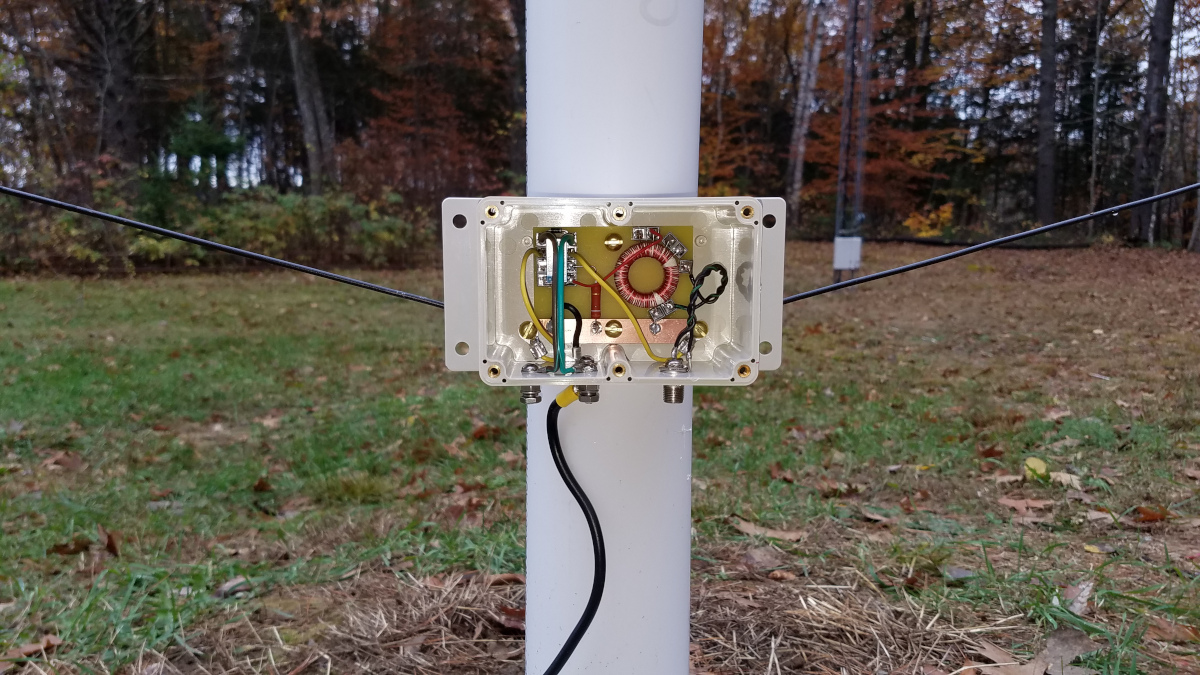
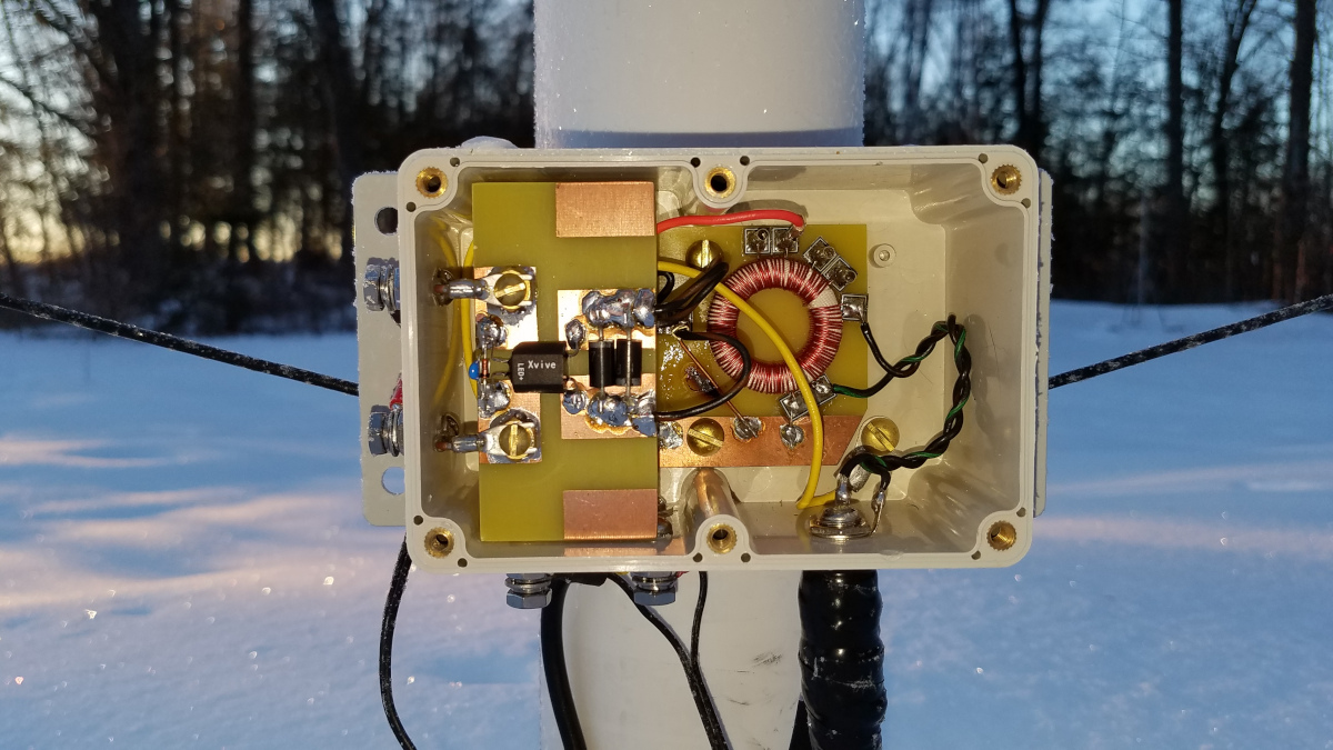
Over several weeks it became apparent the antenna’s performance was not stable. The pattern seemed to improve and worsen with environmental factors such as temperature and snow cover. Several other K9AY loop users suggested improving my ground system might help stabilize it but with snow already on the ground I decided that would not be practical until spring. I decided to modify the K9AY to use a vactrol instead of a fixed resistor for the termination. A vactrol is essentially a voltage variable resistor consisting of a LED and a photocell in a small four lead package. I obtained a VTL5C4 vactrol made by Xvive and installed it on the K9AY. Additional control conductors were run to the antenna so I could control the termination resistance remotely from the operating position. This change has thus far allowed achieving at least 17 dB front to back using sky wave signals as a reference on any given night. There have been times when I see more than 30 dB front to back on DX signals. I have no explanation for that, since the computer model suggested a maximum of 17.5 dB. Front to back often undergoes short term changes which I suspect are due to changing vertical arrival angle of signals, possibly with some contribution from skew path signals if that phenomenon exists on 2200 meters. Skew path is common on 160 meters. Termination resistance typically requires adjustment with major temperature changes and after significant snowfall events.

Modified K9AY loop box with vactrol for variable termination resistance

So, with those changes made, how does it work? Better than expected! I have been comparing antennas by listening simultaneously on both using identical receivers feeding identical sound interfaces on the same computer. I am using six instances of WSJT-X monitoring three modes: WSPR2, FST4W-120, and FST4W-1800. SNR as reported by WSJT-X is recorded for every signal received and each antenna it is received with. From that data, the following results have been extracted and calculated. The method is not perfect as there is uncertainty in the reported SNR, especially with weak signals near the decoding threshold. However it is the most practical method to get a reasonable comparison.

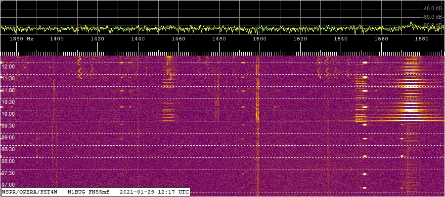
Before getting into the results, I should point out that having the new directional antenna has confirmed something I already suspected: I have more man made noise to the southwest/west than to the northeast/east. This means I get a bigger advantage from the K9AY loop when listening to signals from the northeast, which puts many of my local noise sources off the back. Any advantage when listening southwest is largely nullified by the fact that my local noise mostly comes from that direction. During the day, when atmospheric noise is not a factor, my noise floor increases between 2 and 5 dB in the southwest direction compared to northeast. In addition to this increase in the overall noise floor, a number of “interference lines” and some narrow smears can be seen.

The WSPR/FST4W band segment. Northeast prior to 0930Z, southwest thereafter. Note more interference lines and squiggles southwest and the appearance of WB5MMB (1550 Hz) and WH2XND (1575 Hz) WSPR signals.
The WSPR/FST4W band segment, Northeast prior to 0930Z, southwest thereafter. Note the huge increase in WH2XND’s WSPR signal at 1575 Hz.

Results from the night of 22/23 January, 2021: With the K9AY loop listening northeast, a total of 35 transmissions from European stations were received. Of those, 21 were decoded only on the K9AY loop, while 14 were decoded both on the K9AY and the LNV. Of the latter 14, signal to noise ratio was always better on the K9AY, the improvement ranging between 3 and 7 dB for an average of 4.3 dB. While listening southwest, a total of 47 transmissions from stations in that general direction were received. Of those, 45 were decoded on both antennas with an average advantage of 0.3 dB to the K9AY. One transmission was decoded only using the LNV and one using only the K9AY.

Results from the night of 23/24 January, 2021: Listening northeast, a total of 56 transmissions from European stations were decoded; 25 only on the K9AY and 31 on both antennas. Of the 31, S/N ranged from 2 to 7 dB better on the K9AY for an average of 4.0 dB. Listening southwest, a total of 66 transmissions were received from stations in that direction; 62 on both antennas with an average advantage of 0.2 dB to the K9AY, 3 only on the LNV and 1 only on the K9AY.

Results from the night of 24/25 January, 2021: Listening northeast, a total of 89 transmissions from European stations were decoded, 45 only on the K9AY and 44 on both antennas. Of the 44, S/N ranged from 1 to 11 dB better on the K9AY for an average of 5.5 dB. The k9AY gained greater advantage later in the period. This may have been due in part to increasing static from storms over the central U.S. Listening southwest, a total of 12 transmissions were received from stations in that direction. All were decoded on both antennas with an average advantage of 0.3 dB to the K9AY.

Results from the night of 25/26 January, 2021: Listening northeast, a total of 17 transmissions from European stations were decoded; 7 only on the K9AY and 10 on both antennas. Of the 10, S/N ranged from 2 to 6 dB better on the K9AY for an average of 4.0 dB. Listening southwest, just one transmission was decoded, and only on the K9AY. However, it was a good one, AX4YB (VK4YB with a special prefix for Australia Day).

Results from the night of 26/27 January, 2021: Listening northeast, a total of 6 transmissions from European stations were decoded; 1 only on the K9AY and 5 on both antennas. Of the 5, S/N ranged from 1 to 5 dB better on the K9AY for an average of 3.6 dB. Listening southwest, a total of 18 transmissions were received from stations in that direction; all were received with both antennas with an average advantage of 0.3 dB to the LNV.

Results from the night of 27/28 January, 2021: Listening northeast, a total of 27 transmissions from European stations were decoded; 6 only on the K9AY and 21 on both antennas. Of the 21, S/N ranged from 2 to 6 dB better on the K9AY for an average of 2.8 dB. Listening southwest, a total of 49 transmissions were received from stations in that direction; 45 on both antennas with an average advantage of 0.4 dB to the K9AY, 1 only on the LNV and 3 only on the K9AY.

Results from the night of 28/29 January, 2021: On this night my local noise was somewhat lower than in previous nights, which may have contributed to slightly different results. Listening northeast, a total of 24 transmissions from European stations were decoded; 7 only on the K9AY, 1 only on the LNV and 16 on both antennas. Of the 16, S/N ranged from 0 to 4 dB better on the K9AY for an average of 2.3 dB. Listening southwest, a total of 47 transmissions were received from stations in that direction; 44 on both antennas with an average advantage of 0.6 dB to the K9AY, 3 only on the K9AY. VK4YB was received twice on each antenna, the first time with a 2 dB advantage to the K9AY and the second time equal on both antennas.

Results from the night of 29/30 January, 2021: Northeast there were a total of 21 transmissions from Europe decoded. Of the 10 captured on both antennas, S/N ranged from 2 to 4 dB better on the K9AY for an average of 2.7 dB. Southwest had a total of 38. 37 were received on both antennas with an average advantage of 0.1 dB to the K9AY. One was decoded only with the LNV.

Results from the night of 30/31 January: Northeast had a total of 8, four being heard with both antennas with S/N favoring the K9AY between 2 and 3 dB with an average of 2.7 dB. Southwest there were 40 in total, 36 being heard on both antennas with an average advantage of 0.4 dB to the K9AY. Two were heard only with the LNV and two only with the K9AY.

These results should be considered in the context of “what can I receive with one antenna that I cannot with the other” rather than “how many dB better is one antenna than the other”. Why? Because of the noise blanker settings I am using for the FST4W modes in WSJT-X. The way I have it set, it will first try to decode without any noise blanking. If that succeeds it will stop there. If not it will next try with a noise blanker setting of 5%. If that succeeds it will stop there. If not it will in turn try 10, 15, and 20% but it will stop at any point if a successful decode is obtained. What this means is that if on a given antenna it is able to decode a signal without using the noise blanker or with a low noise blanker level, it makes no attempt to see if it could get a better signal to noise ratio using more noise blanking. But when decoding on the “weaker” antenna it might get one or more levels deeper into noise blanking before obtaining a decode. This can have the effect of reducing the reported difference in S/N between the two antennas. During these tests I saw many cases where it decoded almost immediately on the K9AY but took longer on the LNV. This suggests on the LNV it was requiring more noise blanking to succeed, and that some of the decodes on that antenna might not have happened at all if I used no noise blanking or only one fixed setting. So if anything, the advantage of the K9AY is likely understated in these tests.

While not formally summarized in the above results, I have been paying attention to apparent front to back when receiving signals off the back of the K9AY. I say apparent because I am not switching the K9AY to the other direction but instead comparing the S/N ratio on the LNV to that of the K9AY. One some nights, apparent front to back is typically 10 to 15 dB with some values in the single digits. Other nights it ranges from single or low double digits to 24 dB or more. I suspect at times it is even more. For example I received a transmission from WH2XND at 0 dB S/N on the LNV but it did not decode at all off the back of the K9AY and could not be seen on any of my waterfalls, fast or slow! That would suggest something on the order of 30 dB difference between the two antennas.

The bottom line is that I am receiving a lot more European DX thanks to the K9AY loop. This antenna is well worth the work and expense that went into it.

Intermittent listening on 630 meters prior to the vactrol modification suggested an even bigger improvement northeast over the LNV on that band, though no formal comparison was made to to lack of a second receiver. On this band there may have been more advantage to the K9AY in the southwest direction but it was hard to tell with just one receiver.

Diagram of the LF/MF K9AY Loop

Improving the Ultrasonic Unit

The proprietor of Midnight Science decided to improve the RX2 design. Thissparker.jpg was great news! I volunteered to help with testing and some experimentation with component values. To help with this I needed a stable spark source. I constructed a spark gap using heavy electrodes mounted to large aluminum blocks that act as heat sinks.  I ended up running 1500 volts AC on this thing, with a 100,000 ohm current limiting resistor. You could really smell the ozone generated by this contraption!

The process started with modifications to the RX2 and progressed through several prototypes. The resulting RX3 can reliably hear the sparker at 100 to 105 feet in calm conditions. This is a considerable improvement over the stock RX2 which lost the signal at 35 feet from the spark.

Some of my power line noise problems had been fixed by the time the final RX3 was ready, but the prototypes had found noise at more than 60% of my RF noisy poles. This is a remarkable improvement over less than 20% with the RX2.

I regret to say I am still not happy with the dish. I am certain this thing loses several dB of performance due to shape irregularities. This is a subject I will be revisiting at a later date.

Sniffing Power Line Noise with UHF

I realized after my first few noise hunting expeditions, VHF alone wasn’t going to cut it. There were too many situations where noise levels would be so nearly equal at several poles I could not be certain which one was the actual source. According to books and experience of others, UHF was the answer to this.

I spent some time looking for an inexpensive UHF AM receiver I could build, but ran into problems. Most of the published circuits used parts that are no longer available. I considered buying an MFJ-852 and buying or building a converter to go with it. I still feel that might be an ideal solution due to the wide receiver bandwidth of approximately 100 kHz.  I would still very much like to try that if I had any money left! However in the end I bought an Alinco DJ-X11 wide band all mode receiver. There were a number of choices, mostly dual or tri band handy talkies with wide band receive. I settled on the Alinco because of its I/Q output feature, which I believe may prove useful in analyzing RFI at some point. Since I have recently been named chair of our club RFI committee, I was also interested in this receiver for its wide range all mode capability. It should prove to be a very useful tool in dealing with other types of RFI.

445-mhz-rfi-yagi.jpgI needed a directional antenna for some UHF frequency. I had an old homebrew 11 element 440-450 MHz yagi in storage. After digging it out I realized it was a bit too long for comfortable use in the field. However, it was a simple linear taper design, wherein element spacing and director taper is constant. Usually such yagis are reasonably forgiving of changes in length. I modeled it in software to be sure, then shortened it to 7 elements, a more practical size. Field tests verified the antenna still had a good pattern after being shortened.

My first stop on the power line tour with the new UHF setup was an area where I had been having difficulty locating the exact source on VHF. The new system left no doubt. While I did get approximately equal noise from two adjacent poles when standing near each of them and pointing the yagi toward the top of the pole, I got a very different and revealing result when surveying from a distance. Imagine a string of 5 power poles in a straight line, equal spacing between poles, with the middle pole (number 3) being the one that is sparking. When standing at the base of pole 3 and pointing at pole 2 or pole 4, I got a minimal amount of noise. When standing at pole 2 or pole 4 and pointing toward pole 3 I got a much higher noise reading. When standing at pole 1 or pole 5 and pointing toward pole 3, I heard noise but at a much lower level. This indicated pole 3 as the source, which agrees with what the power line noise troubleshooter told me about that area. He found a bad lightning arrestor on pole 3. I was sold on the value of UHF in the tool kit at that point!

Results were not quite as conclusive in all areas. One in particular, where there are two poles with “prime suspect” hardware just 40 feet apart, remains somewhat perplexing. Nevertheless, I won’t be leaving home on power line noise hunting expeditions without my UHF sniffer!

Ultimately I was not satisfied with the Alinco for hunting power line noise. Instead of a distinct buzz, power line noise at any frequency in AM mode sounded more like a muted hiss. Unless quite strong it was hard to distinguish from the steady hiss of the receiver internal noise. A very strong signal was required to get any S meter deflection at UHF. Compared against other receivers. the Alinco performed very poorly for noise hunting. I have since sold it and will get something else after doing some research.

Unscientific Method for Reducing Ethernet Birdies

I have been plagued by ethernet birdies from my own home for several years. I have a router, DSL modem, two access points (one mounted atop one of my ham towers), and two PCs which are alternately connected either by ethernet cables or via wireless to my in-house access point.

Previously I had made an attempt to reduce the birdies by putting various ferrite chokes on the assorted cables associated with the network. The methodology at the time was to tune in a strong birdie near 50.110 MHz to use as a progress indicator. I then worked on the cables one at a time, adding chokes to a particular cable until I could not detect further improvement, then moved on to the next cable. At the end of the day I had reduced the birdies about 10 dB but I needed at least another 10 dB to be reasonably satisfied.

Having just bought an Alinco DJ-X11T wideband receiver, I started sniffing around cables by placing a few inches of each cable parallel to the DJ-X11T antenna. I found most of them still seemed to be radiating noise despite having chokes on them. I used the same strong birdie near 50.110 MHz since 6 meters is the band I care most about.

checking-ethernet-cable-for-rfi.jpgI decided to try a slightly different approach to the problem. Starting with one cable, I added or modified chokes until I could hear very little or nothing on that cable with the DJ-X11T antenna tightly coupled to it. When I got one cable quiet using this method, I moved on to the next. I ran out of ferrite cores before finishing all the cables, but the noise is down another 12 dB from where it was! Purists will no doubt find flaws with my method, and I can’t be sure it would work in all cases. All I can say is it helped me get this problem a lot closer to being under control.

The chokes are not all the same. I used whatever ferrite cores I had on hand. Some are a few turns of cable on “known” cores such as Fair-Rite type 31 material 2.4″ OD toroids. Others are a single pass through unknown clamp-on cores or 2 or 3 turns through a clamp-on core. When core size allowed more than one pass of a cable through it, I experimented with the number of turns until I obtained optimum results. There is usually a point where adding another turn actually makes things worse, so it was easy to find the optimum number.

The 6 meter birdies are rather weak now. When I get more cores I will finish up the wires I didn’t complete this time and see if these can be reduced even more.

Books and Other Resources on Power Line Noise

I bought a copy of “AC Power Interference Handbook” by Marv Loftness (KB7KK). While written by a professional for professionals, this book is an excellent and easy to understand resource for the rest of us. I highly recommend it to anyone having power line noise problems. The book is available from ARRL and other book sellers.

Another excellent resource is “The Mitigation of Radio Noise From External Sources at Radio Receiving Sites”. This is from Naval Postgraduate School and is in the public domain. As far as I know it is only available as a PDF file. You can download it here (6 MB file size).

The ARRL web site has an extensive section on power line noise.

Ultrasonic Detector: Midnight Science RX-2 and 12″ Dish

After reading “AC Power Interference Handbook” by Marv Loftness, and based on my own experiences trying to identify sparking poles at VHF I decided to add an ultrasonic detector to my power line noise hunting arsenal. The question was which unit to try. Commercial ones start around $3500. If I had the disposable income most DXers seem to have these days, I probably wouldn’t bat an eyelash at that. If it helped get my hobby back it would be well worth it. However, since I was already selling off bits of my station in to be able to buy low-end noise hunting apparatus,  those were out of the question. It came down to two options: it was either going to be homebrew based on the article by W1TRC or the Midnight Science kit offered by the Xtal Set Society. Unfortunately there wasn’t much solid information on how effective either unit is in practical deployment. I found a lot of others wondering, but nobody providing information to shed any light on the matter.

Having finally decided on the Midnight Science offering, I ordered an RX-2 receiver and the companion 12 inch dish kit. This isn’t intended to be a product review but upon opening the box I was immediately disappointed with the dish. It is quite flimsy and arrived deformed so that it did not conform to a true parabolic shape. For $130 I expected a bit more. The receiver seems like a well thought out kit and went together very smoothly. It passed initial tests as outlined in the manual. There is a review of this kit here.

After spending a day evaluating the unit, I’ve been forced to conclude as supplied it is a marginally useful instrument for my application. I thoroughly checked out 16 poles that were very RF-noisy, but could only hear something from 3 of them with the ultrasonic unit. Two were just barely detectable while the third produced a good strong ultrasonic signal. Is the unit not sensitive enough for this use? Or are most of my line noise problems caused by sparking inside a device such as a lightning arrestor, which doesn’t permit ultrasound to escape? I have no way of knowing for certain.

Tracking Power Line Noise With The MFJ-856

I have spent some 50 hours over the last two weeks hunting for power line noise with my modified MFJ-856. I’m learning it’s not quite as easy as it sounds and there are some tricks of the trade that one picks up along the way. Today I will share some of my experiences and things I’ve learned so far.

It is very important the noise not overload the meter when you get close to a source. One needs to be able to see peaks and nulls while rotating the unit. As noted in a previous post, switchable attenuation is an absolute must in my area. Our distribution lines are on the high voltage side at 13 kV or so. I also have two 46 kV transmission lines to contend with.  Perhaps these high voltages contribute to the need for attenuation. I have not had the opportunity to try it in an area with lower line voltages.

Walking works best. I’ve found the best way to hunt noise is on foot. From a vehicle, it would be very difficult to manipulate the 856 to take readings. I find it necessary to rotate the unit very often, not only around the points of the compass but also up toward an overhead power line.

Keep the yagi moving. I found walking under or nearly under the power line is usually a good idea. I aim the yagi at each pole as I pass, preferably varying the angle as I do. I rotate the yagi so the elements are parallel to the overhead wires, and also try perpendicular.  I point at the top of the pole (where all the stuff is!) at an angle before I  reach it, while passing in front of the pole, and after I’ve passed it. I note any noise heard, its relative strength, and any unique sound or “signature”.  Pointing the yagi toward the horizon is a good way to locate noisy poles far away, but I don’t walk along with it in this position. Doing so can lead to hearing noise from afar but missing a noisy pole that I walk right past! Sometimes it is useful to stop and do a full 360 degree “sweep” of the horizon to see what directions might be noisy. This can lead one toward problem areas. I try this with the yagi horizontally polarized (elements parallel to the ground) and vertically polarized (elements in a plane perpendicular to the ground). Sometimes one polarization works better than the other.

Finding the source pole. Once a small area has been confirmed to contain a noise source, it is time to start taking measurements to find the source pole. Stand at least 20 feet away from the power line (more is better) an equal distance from two poles. Point the yagi at one pole and take a signal strength measurement. Do the same for the other pole. Whichever pole has the higher reading, move to a point between it and the next pole and repeat the process. Keep going until you find one pole with a higher reading than all the others. This is sometimes very difficult with the MFJ due to its limited S meter resolution.

Use attenuation. If I’m getting full scale readings on the meter from more than one pole in a small area, I increase attenuation to knock the signal down. This often helps isolate which pole the noise is actually coming from.

Use the nulls. There is a deep and relatively sharp null directly off the side of the yagi. It is much narrower than the peak off the front and can be used to help verify a noise source. Think of orienting the yagi so that the driven element itself is a pointer that you are using to “point out” a spot to an audience. Noise will be minimum when the end of the driven element is pointed directly at the source. When I find two adjacent poles that seem to have about the same noise level (yagi pointed at them), I can often stand half way between and use this technique to determine which pole is actually responsible. Of course it could be both!

Be aware of obstacles. When pointing toward the horizon to home in on a distant source, I found  it is important to be aware of obstructions. Sometimes the signal will seem to get weaker as I walk along. This may or may not mean I have missed the source. Is there a hill or rise in the direction of the noise? Buildings? Forest? These can all attenuate the signal. I learned to try going around, over, or through such obstacles (as appropriate) and see what noise readings I find on the other side. I was going crazy trying to figure out what was happening in one area until I realized this!

Conducted noise and re-radiation. Even at 135 MHz I found sometimes noise can be conducted along the power line for considerable distances, then radiating from many poles in an area! It can be quite a challenge to home in on the real source in these cases. So far these seem to be the more intense noise sources. In general the noise gets stronger closer to the source, but anomalous peaks can happen at poles where lines cross or which have more or different hardware than neighboring poles. Is this pole noisy in its own right or is it simply a good radiator for noise generated elsewhere and conducted along the power line? Good question! Sometimes it impossible to know. I try to concentrate on the sound of the noise. Is it a buzz? Hum? Frying sound? Does it sound different at this pole, or is it the same sound I’ve been homing in on? If it sounds different, there is a good chance there is some additional problem on this pole. If not, it may be just that this pole is a good antenna for radiating noise “sent” to it over the lines from somewhere nearby.

Alternating peaks at three to four foot intervals. Sometimes while walking along with the yagi pointed ahead or upward toward the power line I find noise peaks roughly every three or four feet, with very distinct nulls between. This is a good indication of noise (RF energy) being conducted along the power line. A half wavelength at 135 MHz is roughly 3.6 feet, which accounts for these peaks and nulls. Recall there will be current maxima and  hence maximum radiation at  half wave intervals along an antenna (or a feed line operating with standing waves on it).

The “sea of noise”. I found some areas where noise is so intense I need to use high attenuation to keep the meter from being saturated. The area may encompass several poles. It is entirely possible that lesser noises will be completely missed in such areas because the strong one masks them.

Vburnedxarm.jpgisual inspection. Take a long hard look at the hardware on poles identified or suspected as the source of noise. Walk around it, if possible, and take a really good look. Sometimes you can see evidence of the problem. When I found this noisy pole I didn’t see the obvious – until days later when the power company troubleshooter showed me a picture he had taken. It’s so obvious I can’t believe I missed it! I went back and took this picture.  Look at the wooden cross arm with a hole burned in it from sparking and heat! Click the small picture to enlarge it. This pole is not only generating RFI but could eventually become a safety and down-time issue for the company.

I find the modified MFJ-856 to be an extremely useful tool, but some ambiguity as to the specific source of noise can still exist. I am seriously thinking about getting an ultrasonic detector for my line noise tool kit. That should help isolate the specific source in areas where the 856 leaves some question.

Modifying The MFJ-856

Power line noise has been on the increase for several years, but after a previous experience trying to get a situation like this resolved I had become jaded and lacked interest in going down that road again. Also the process is not easy for personal reasons. However, I ran into an old friend at a hamfest who said he had a contact and believed he could get the power company on it. I was shocked when I got a call from the power company troubleshooter a week later. It remains to be seen how this will play out but the initial contact sounded promising.

I needed a way to find noisy poles and I needed it fast. Strike while the iron is hot, my dad always said!  So I ordered an MFJ-856 power line noise meter. For those not familiar with it, this handy device is a wide bandwidth 135 MHz AM receiver mounted on a 3 element yagi. It is very light and easily carried in one hand. Not surprisingly, I took one look and said “needs improvement”. But I went out for a test run anyway, and found it was completely overwhelmed by the intensity of power line noise in my area. It was impossible to get bearings because the antenna pattern nulls weren’t deep enough to bring the meter down from full scale.

I decided it needed three changes:

1) Get the receiver out of the center of the yagi

2) Improve the yagi feed method

3) Add switchable attenuators

First I modeled the yagi in YO and found it had a reasonable pattern as designed. No major changes would be needed other than to the driven element. Next I confirmed by experiment that placing objects or wires in the center of the yagi had a detrimental affect on real world pattern. I also confirmed that placing objects or wires behind the reflector had little or no affect. Great! Now I had a plan!

bug856-feed.jpgI added a T match to the driven element. The T bars are 11.5 inches long #10 AWG copper spaced 1.0625 inches from the driven element, center to center. With shorting bars at 11 inches out from center this produced a nearly perfect SWR at 135 MHz. It is important to note the driven element had been modified slightly. Instead of mounting each element half through the boom using a #10-32 machine screw and hardware, a length of #10-32 all-thread is passed through the forward hole with a nut on each side to secure it. Then the halves of the driven element are screwed onto the all-thread in the same manner as the parasitic elements. bug856-feed-detail.jpgDriven element tube lengths did not need to be changed with this mounting arrangement. The balun is 30.5 inches of RG-303 coax, with the entire center block assembly on an SO-239 with small aluminum angle bracket, attached to the boom with a single #8-32 machine screw.

bug856-att-rcvr.jpgA short length of RG-142B/U coax runs rearward from the feed to just behind the reflector, where it enters a homebrew step attenuator. No connector is used at this point, though one could be if desired. The attenuator uses DPDT slide switches liberated from and old Bell&Howell Schools oscilloscope and standard 1/4 watt 5% metal film resistors. The three attenuator sections are approximately 5, 15, and 25 dB for a total of 45 dB when all are switched in. This is barely adequate in my area! There are times I could use another 20 dB but it’s quite usable on most noises as it is now.

The attenuator is attached to the MFJ receiver using two #4-40 machine screws.  The receiver is attached to the boom with two #8-32 machine screws.

Click on the thumbnails to see high resolution pictures. Try to ignore my little helper buddy there! If he sees a camera, he shows up hoping to get his picture taken! Which usually works, because he makes it a point to be wherever the object being photographed is… as you can see here.

bug856-overall.jpg

bug-856.jpg

Attenuator schematic