Category Archives: MF & LF

2021 Antenna Rebuild: The Complete Story, More or Less

I have a passion for radio, but it goes deeper than a hobby for me. As I continually struggle to maintain my relative independence amid the challenges of some very frustrating and debilitating challenges, it is a survival tool. To that end it is important enough to be among the highest priorities in life. Thus when misfortune struck I put much on the line to recover.

Over the past several years, with sacrifices on my part combined with generous contributions from fellow hams I have been on a station building spree. I got back into VHF/UHF weak signal work, greatly improved my HF antennas, and for some time was heavily into experimenting and attempting to work DX on 2200 meters. Things were going very well but all of that changed one winter night in December, 2020. We had a wet, sticky snowstorm that night. All of my wire and yagi antennas were heavily burdened with snow. At some point the strain was too much for the 2200m T antenna that was suspended between my two 100 foot Rohn 25 towers. It broke at one end and fell. The sudden reduction in side loads on the towers caused them to move slightly. With the burden of extreme weight of the snow, this caused significant, but fortunately not catastrophic damage. Some yagi elements were bent, traps damaged, coax cables damaged, masts bent just enough to bind, and one Rohn 25 top section was bent slightly, causing rotation to be extremely impaired on that one. All of the antennas from both towers were going to have to come down for repairs to themselves and the towers.

Side view of the 2200m antenna before the incident. It is strung from a point 103 feet up a tower on the right, and 95 feet up the tower on the left. That three wire top hat can accumulate a tremendous snow load under the right conditions.
Another view of the 2200m top hat, taken from one of the towers. Failure occurred when the antenna broke free of an insulator at one end.
Base and coil platform for the 2200m antenna. There is matching transformer and tap selection relays in the box at the left, a 2.2 millihenry coil/variometer in the blue drum, and a smaller version of same for occasional use on 630m in the bucket at the right.

There are no photos of the aftermath or 2200m antenna laying in the snow. I was too depressed that morning to want to document anything. I stabilized what I could and over the next several days foolishly repaired the 2200m antenna. That allowed me to continue LF operations until Spring but I knew those days were coming to an end. Assuming I was able to repair the towers and other antennas, I could never again risk a similar disaster.

The first challenge was how to finance repairs. If I chipped away at it with whatever I could manage to set aside from my income, recovery would take years. The other option was to see if I could get a loan, despite my fixed income falling below lender minimum guidelines. I was not doing so well since the loss of most radio activities. Under some gentle prompting from my health support team I decided to pursue a loan. Fate smiled upon me and I got the loan, a sum not less than a third of my annual income. It will take some time to pay that off but I was on my way to rebuilding!

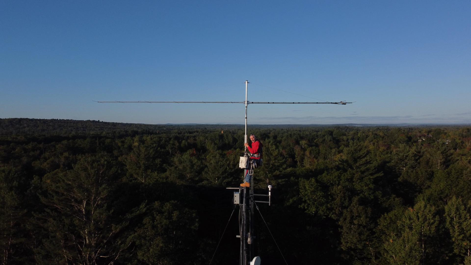
It was going to be a big project for me. I do all antenna work alone. That means a lot of trips up and down the towers, as I have no one on the ground to do anything and must often make several trips up for simple tasks. There were complicating factors going into this. One was that several months earlier we lost a local ham and professional tower worker whom I had known for 40 years. He died in a fall from a tower. To be honest that really shook me up and I had some difficulty with climbing early on in this project because of it. I was at least 40 pounds overweight which compounds that darn gravity thing! But I was going to rebuild or perish in the attempt! Lastly there are always days that I am unable to work or be outside, and that has been greatly compounded by a neighborhood situation which has had several of us making complaints. It was very difficult this year to find times that I could do anything at all. I often started around 2:00 AM and finished work shortly after dawn. These same factors make it impossible to schedule work sessions even when volunteers might be available. Under current conditions I either do antenna work alone or it won’t happen at all. I don’t know how many years I will be able to continue this, so I am making the most of it while I can!

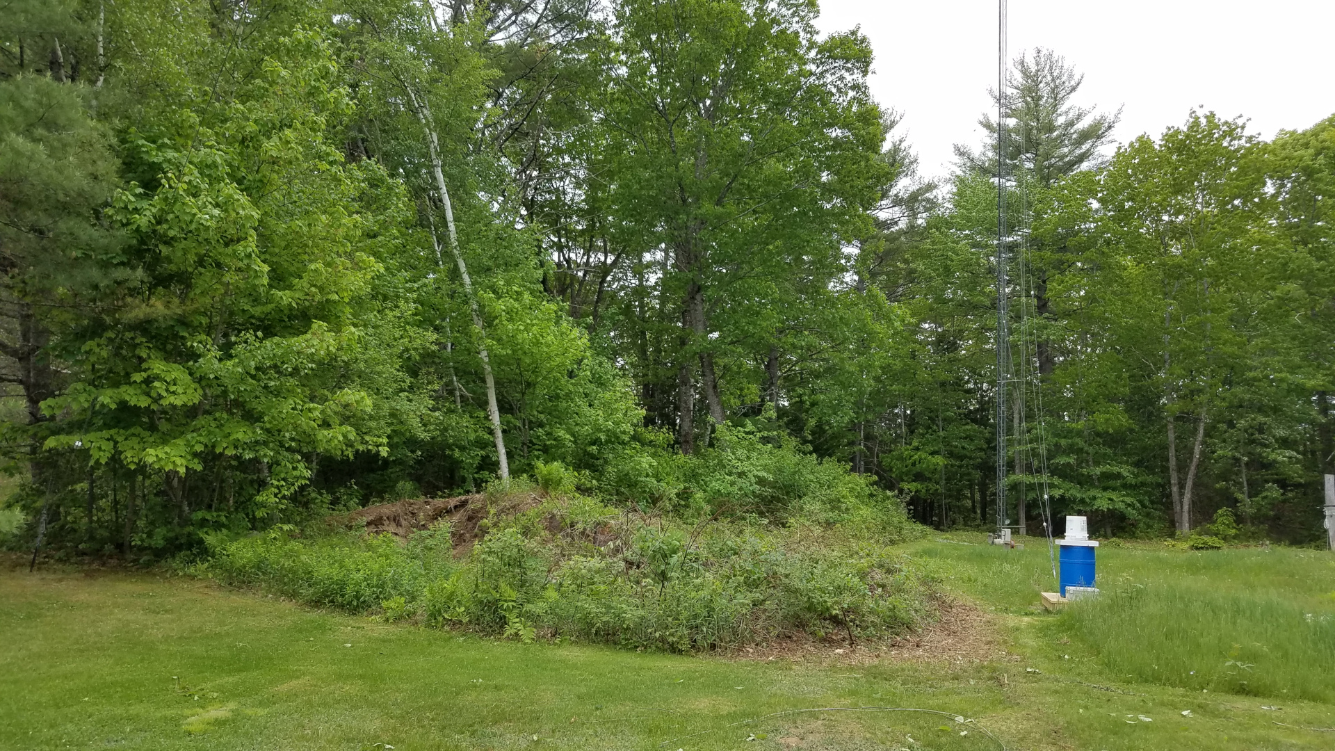
First there were preparations and getting antennas down from the more heavily damaged tower. The 2200m antenna was taken down for the final time, a very sad day since that extremely challenging band had been of great benefit to me. I miss it every day. Some trees that had rather quickly grown up along the path of my tram line were cut, and the tram line was hauled up into place.

The 2200m antenna doesn’t look like much after disassembly! Some coils of wire, three 12 foot aluminum spreaders, and some big honking insulators.
These antennas had to come down, even though things don’t look too bad in this photo. Traps on the TH11DX had broken (shattered!) plastic end caps and were weak and wobbly, some element tips were slightly bent and the boom truss was in danger of failing. Coax had issues on the 6 and 2 meter antennas, boom truss on 2m had partially failed, some 6 meter elements rotated out of plane, and the mast was severely binding in the tower top due to slight bending of both the mast and the tower top section.
Trees have been removed from the area on the left to provide space for tramming.
Ropes and cables for tramming operations. One wire rope is the tram line, the other is a backstay to prevent failure of the mast from the stress of tramming the heavy TH11DX.
The mast backstay attached to a rope and ready to be pulled up.

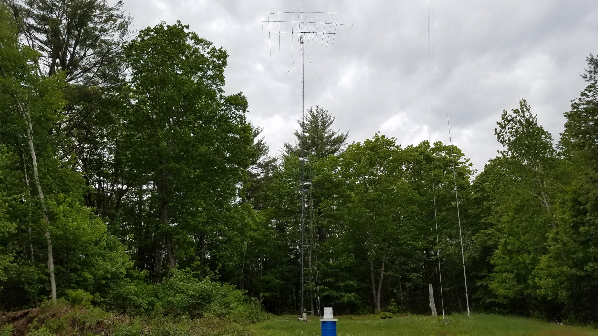
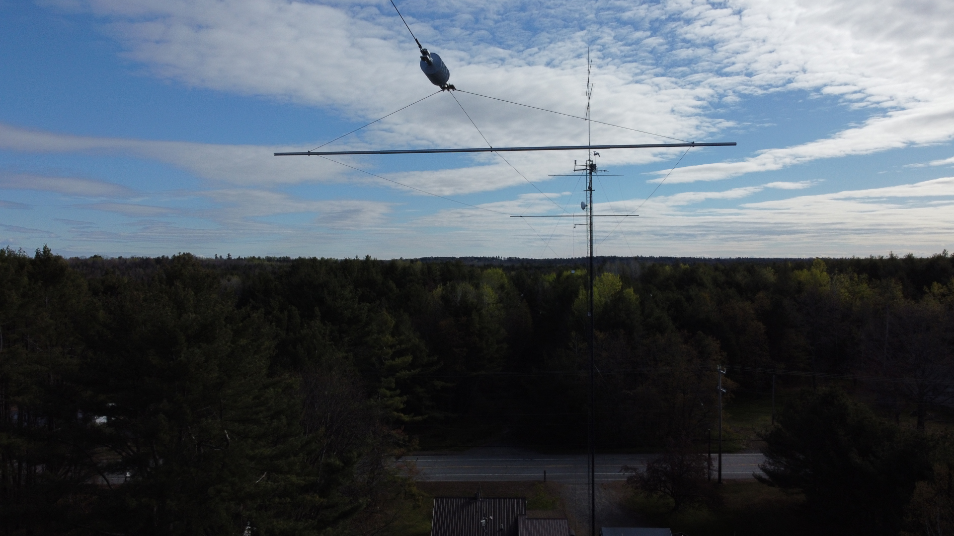
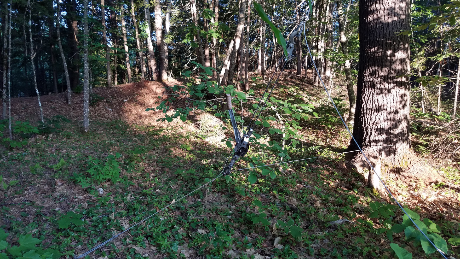
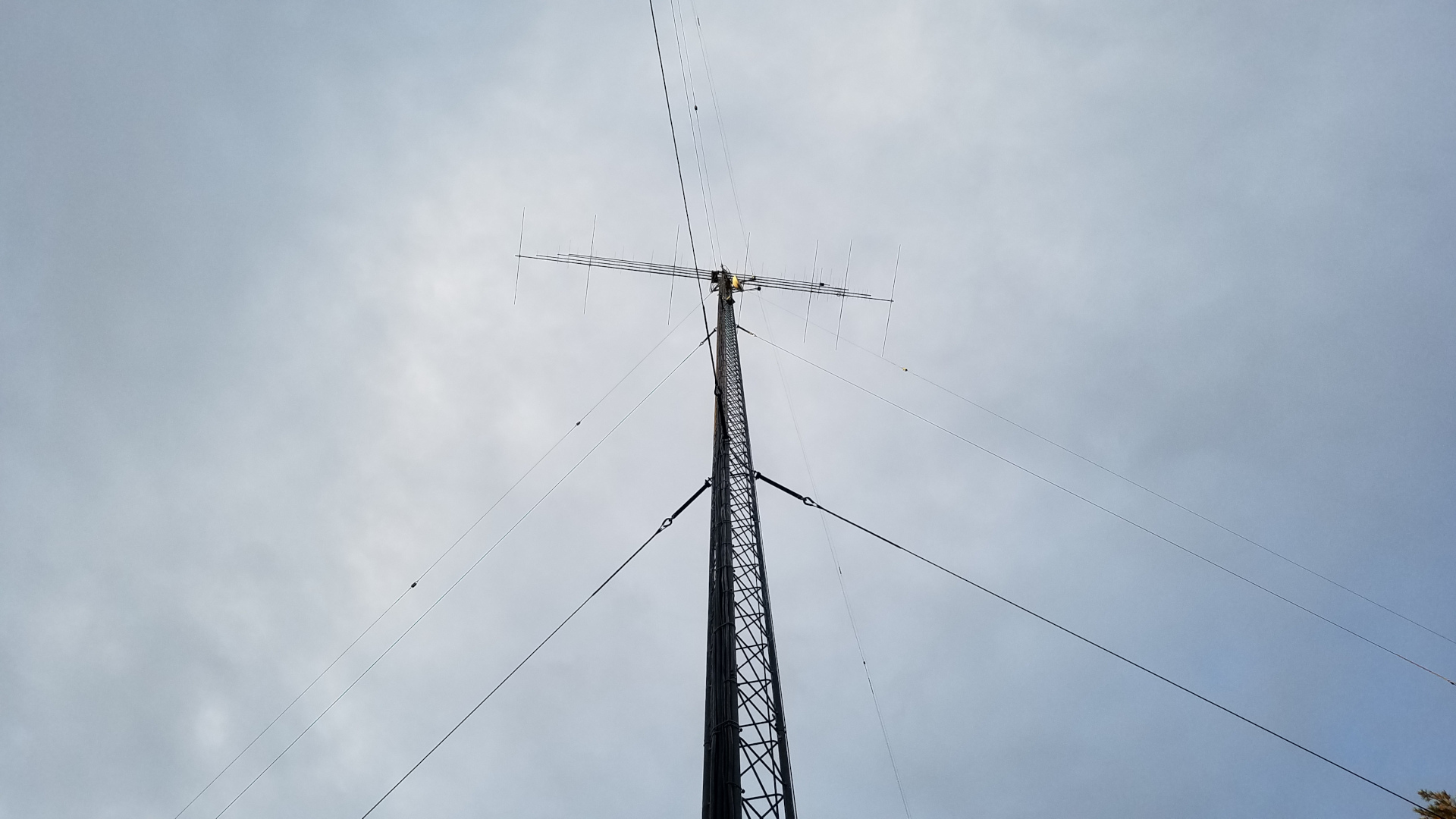
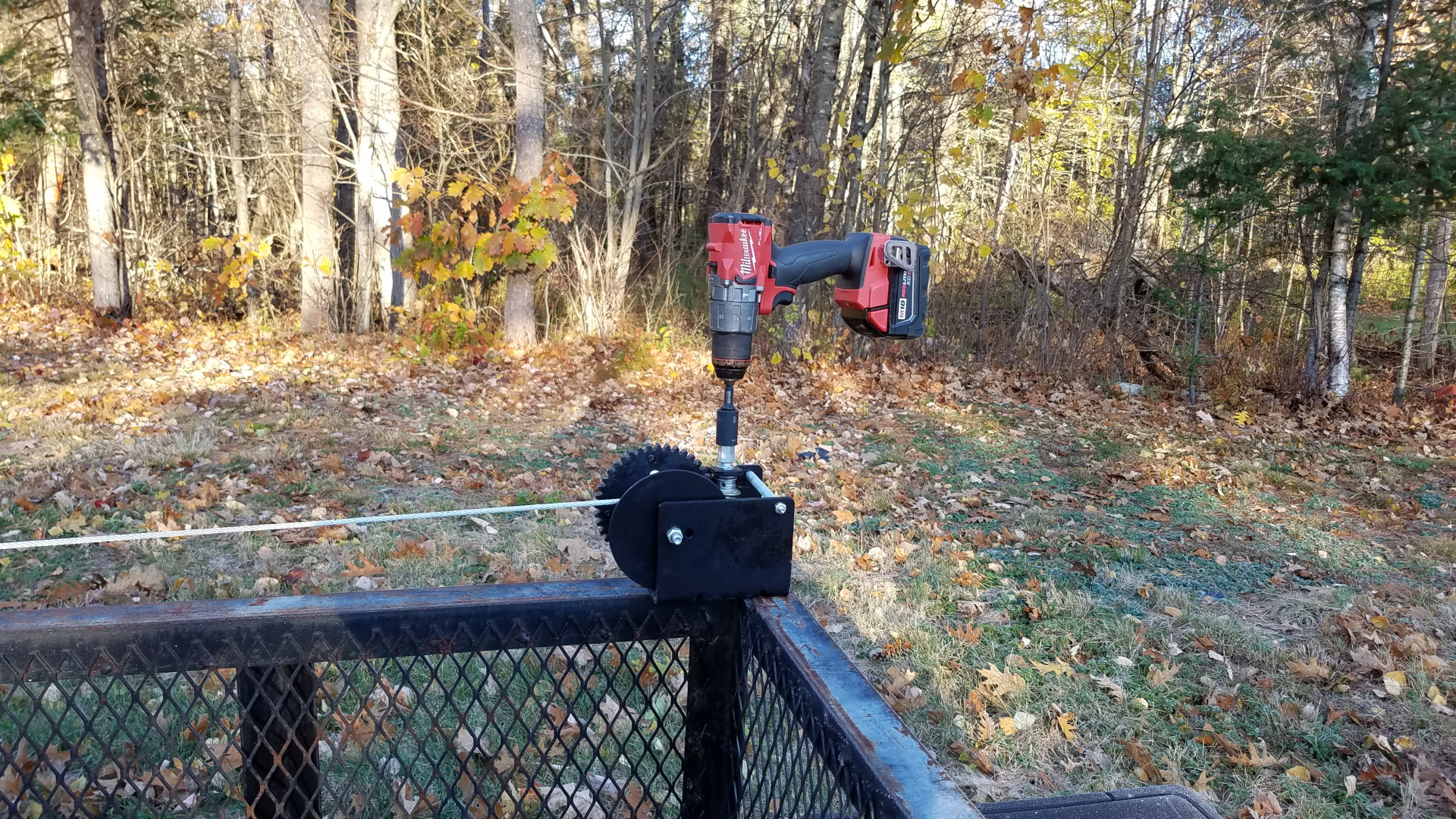
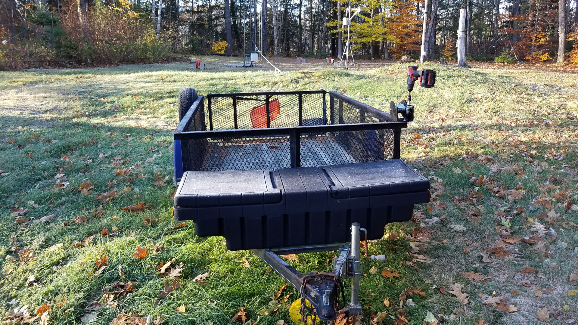
Special tramming operations needed to be carried out for the 6 and 2 meter antennas in order to get them past the elements of the TH11DX. It might have made more sense to remove the TH11DX first, but this was early in the season when I was very nervous climbing. To be honest, this was a mind game. I needed to see the big expanse of the TH11DX below my feet as I stood on a mast step to reach the upper antennas, or I would never get myself up there! I will argue that one should not climb if experiencing such discomfort and having to play such mind games but this was do or die for me. I was willing to take the risk of pushing myself into uncomfortable situations. In order to solve this clearance problem, the tram line was run horizontally from the mast over to the top of the other tower where it was joined to a rope running through a pulley down to a hand winch at the base of the tower. This allowed the VHF antennas to leave the tower going out horizontally, then to be lowered to the ground by letting out rope from the winch.

The 2 meter antenna suspended on the high, mainly horizontal tram line.
Tram line being lowered with the 2m antenna hanging in the middle.
The 2m antenna nearing ground level.
6m antenna out on the high tram line.
Tram line being lowered with the 6m antenna on it.
Since I was still about 40 pounds overweight at this stage, I took advantage of the tram line to bring up my bucket of tools… less gravity pulling at me than if I climbed with it attached to my climbing harness.

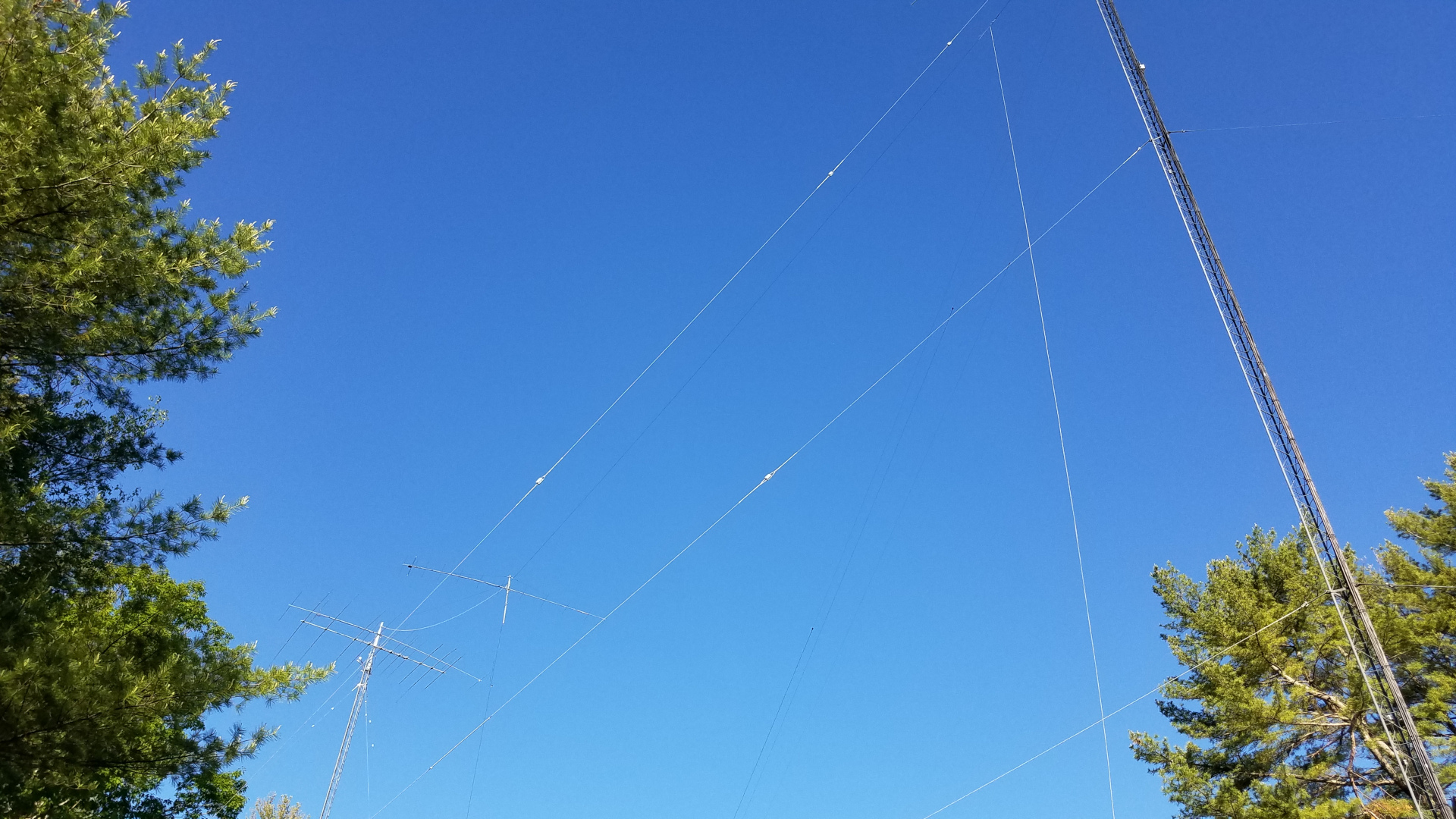
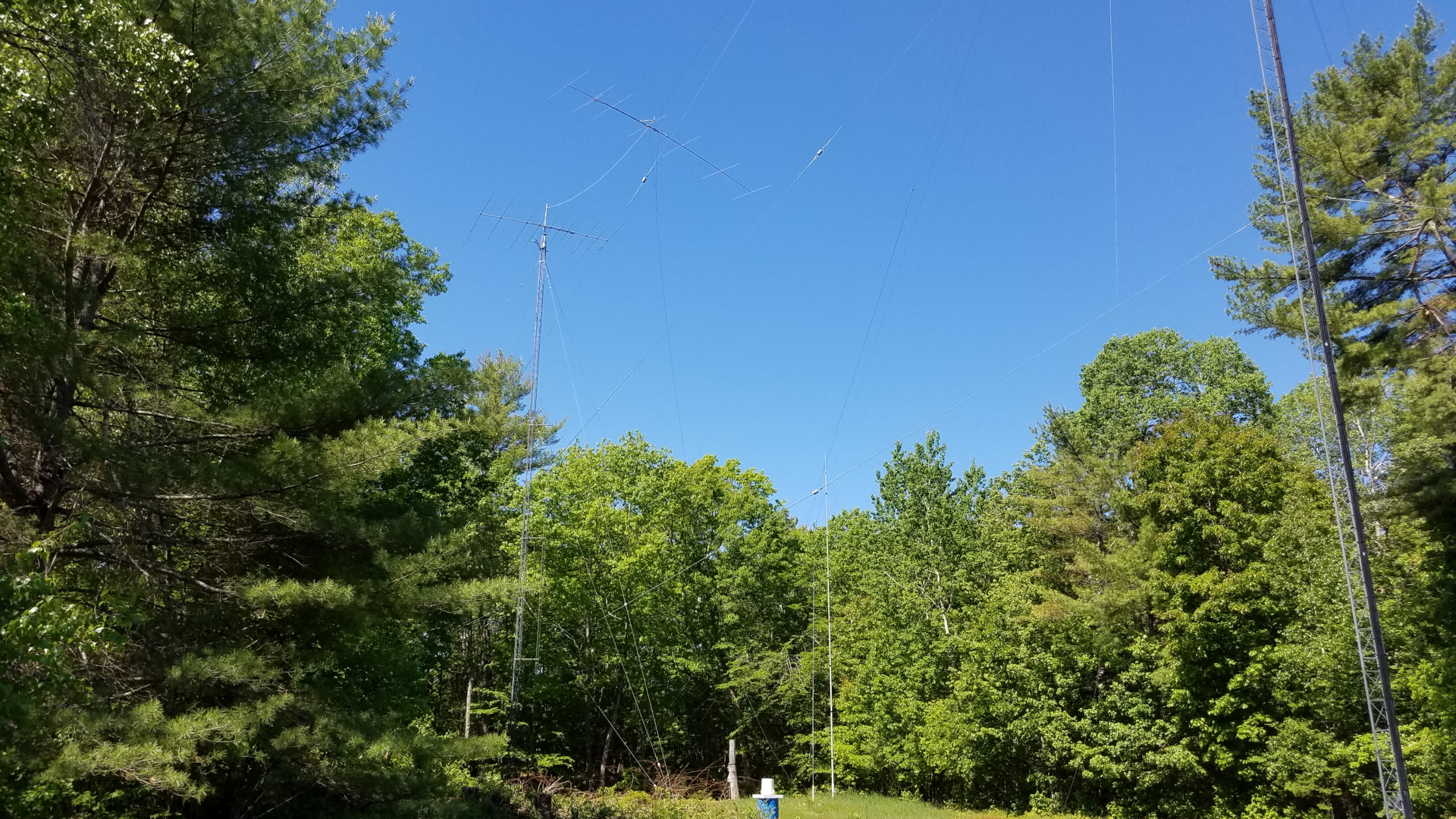
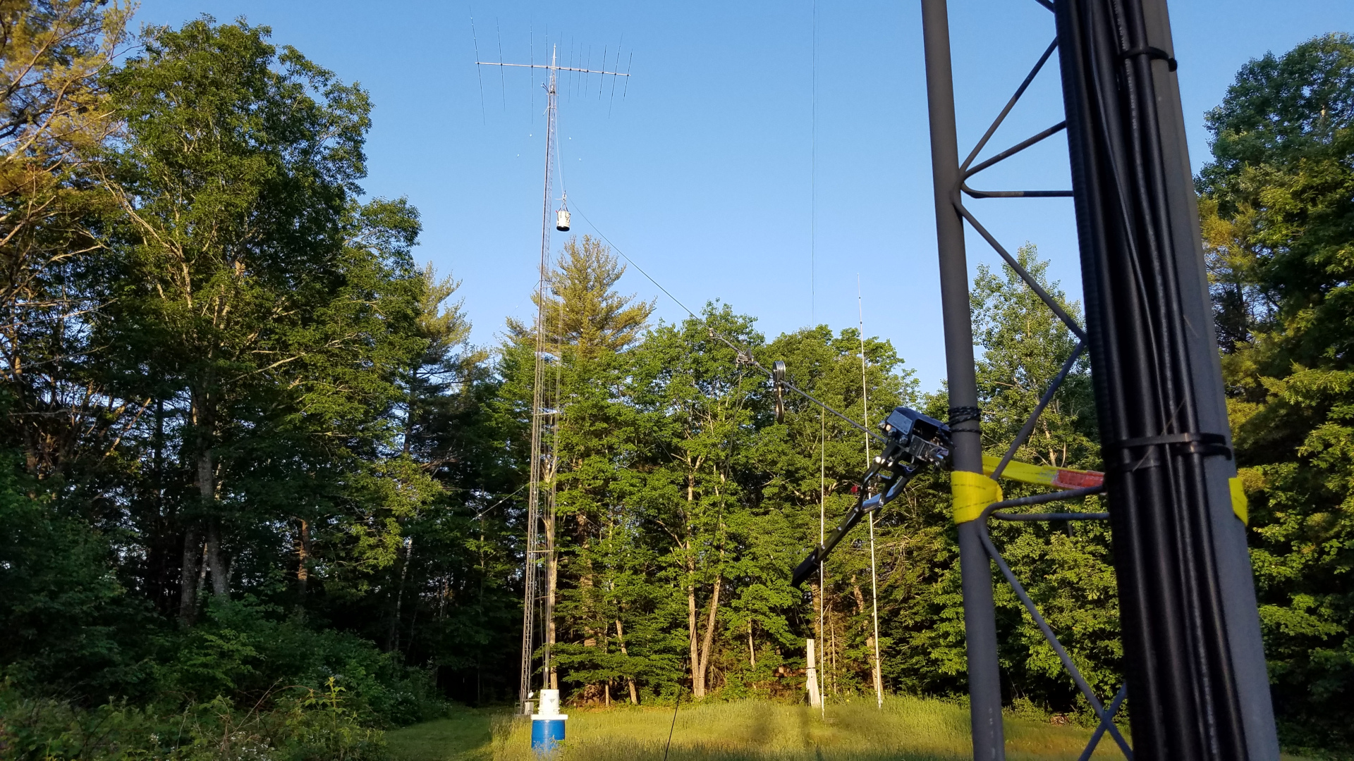
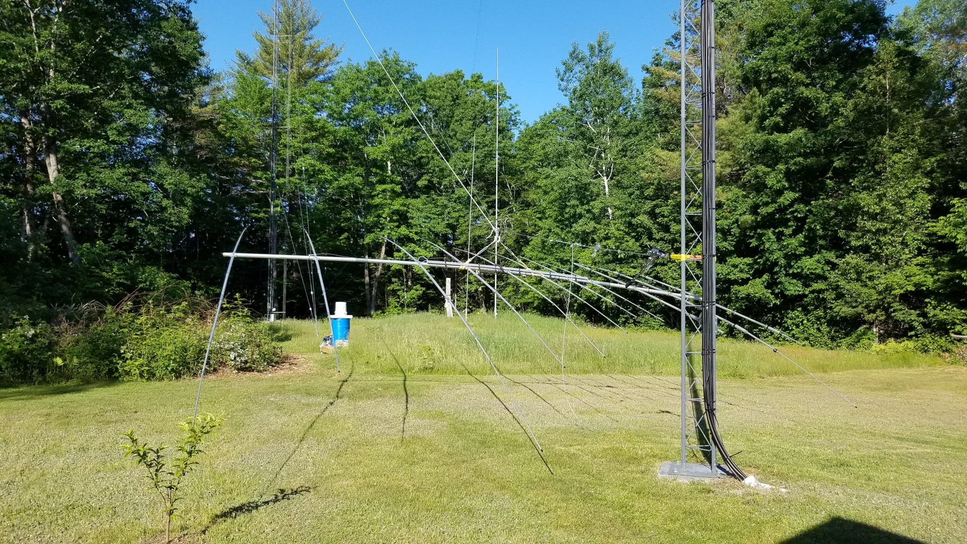
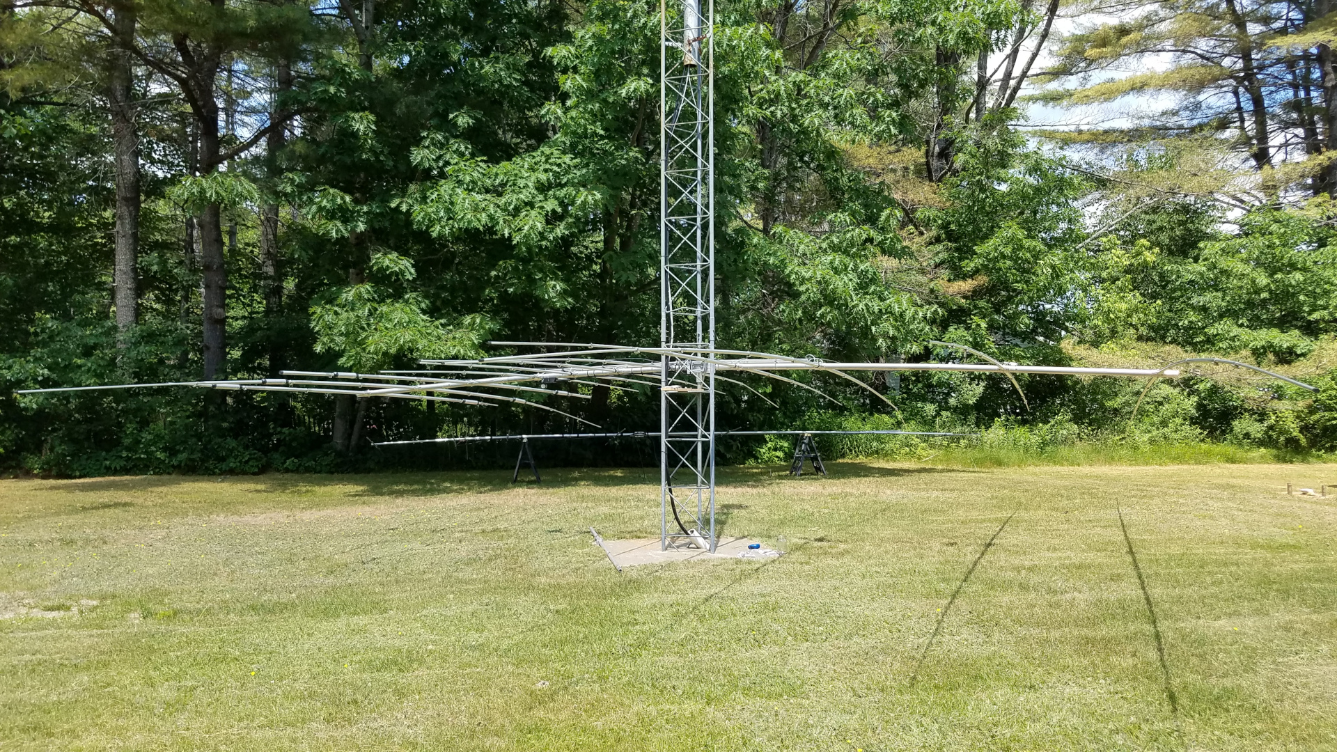
With the smaller antennas down it was time to tackle the TH11DX. For this, the tram was rigged in a somewhat more conventional manner, now going from the top of the mast down to a few feet above ground on the other tower. After the nearly 100 pound antenna was at ground level, I learned that I need to eat more Wheaties or something! It was a struggle to pick it up, walk over to the short Rohn 45 tower with it, and mount it at shoulder level on that tower where it would remain until everything was ready for it to go back up.

The backstay tension system. This is critical when tramming nearly 100 pounds of antenna with a tram line attached to an aluminum mast!
TH11DX suspended on the tram line. The tram line and backstay can be seen.
TH11DX about half way down the tram line.
TH11DX has nearly reached ground level.
Tram line has been slacked off by means of the comealong by which the tram is attached to the slings on the tower. That lowered the TH11DX the final bit onto saw horses.
The TH11DX moved to a temporary spot for repairs.

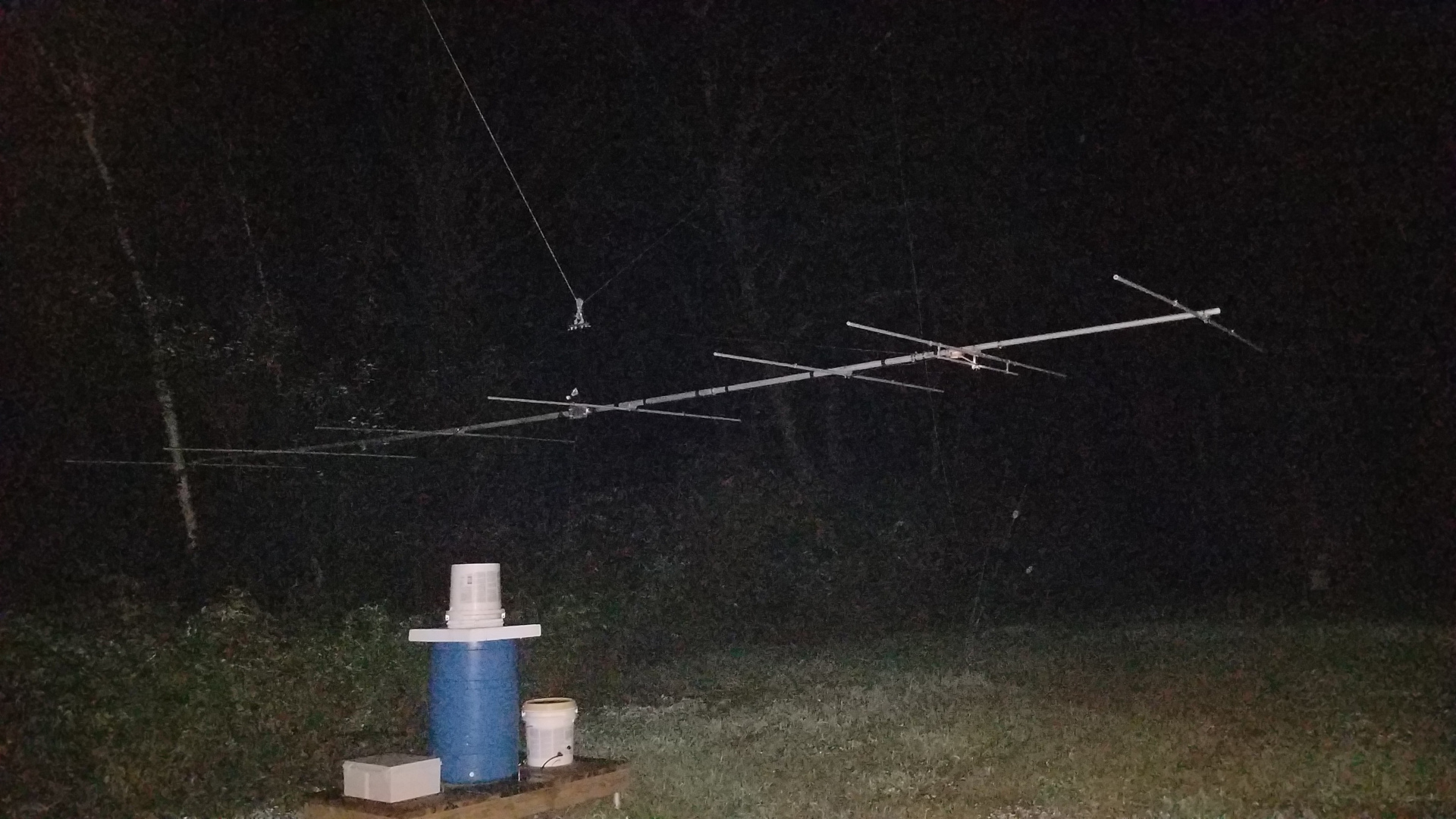
I was not doing so well after months of not having radio which I rely on for stress management, and really wanted to be active for sporadic E season and the Perseids meteor shower. I decided to repair and mechanically upgrade the 2m antenna and then temporarily put it on the other tower, below the 222 and 432 MHz antennas.

New, upgraded 2m boom to mast clamp. Overkill.
New, upgraded 2m truss to mast clamp. Overkill, again.
New 2m truss to boom clamp. The truss itself was upgraded from dacron rope (too stretchy!) to stainless wire rope.
Refurbished and upgraded 2m antenna.
OK, now I am happy with the alignment of elements!
2m antenna on the tram line ready to go temporarily to the northeast tower. Rather than lower HF wires out of the way, I opted to use the same high tram running between the tops of the towers, but in the reverse direction (rope, pulley and winch now on the southwest tower).
Quick and dirty rigging of antenna to tram line, but it works fine.
2m antenna on the raised tram line.
2m, 432 and 222 antennas on the northeast tower.

I caught a couple of massive E skip openings on 2 meters and did very well in the Perseids on both 2 meters and 222. I was glad I took this step of putting the 2 meter antenna up in a temporary fashion. After the Perseids it was time to remove all antennas from the northeast tower and get to work on the new VHF/UHF stack there.

The 6m antenna needed two elements rotated back into plane, new boom to mast clamp, new truss to mast clamp, new coax and a rebuild of the center of the T match.
All of the antennas down for work. 6 and 2 mounted on the utility trailer, 222 and 432 on saw horses, TH11DX on the short tower. 222 and 432 got new coax, new boom to mast, and new truss to mast.
The 2m antenna hanging on the tram line before dawn, ready to go up at first light while there is no wind. It is going up already attached to a 6 foot mast extension.
The 2m antenna is up. Photo clipped from a drone video.

I had a setback after getting 2m, 222 and 432 yagis up and mounted on the mast. While raising the mast to final position in preparation for rotator installation and adding the 6m antenna, the three coax cables got caught on the tower and damaged. I had to take all three antennas down and replace the coax a second time!

6m antenna waiting on the tram line for first light.
Sun’s up! Time to go!
VHF/UHF antennas up, northeast tower work finished (mostly).
I am happy with alignment of booms on this stack.
VHF/UHF stack from above.
VHF/UHF stack just after sunset.

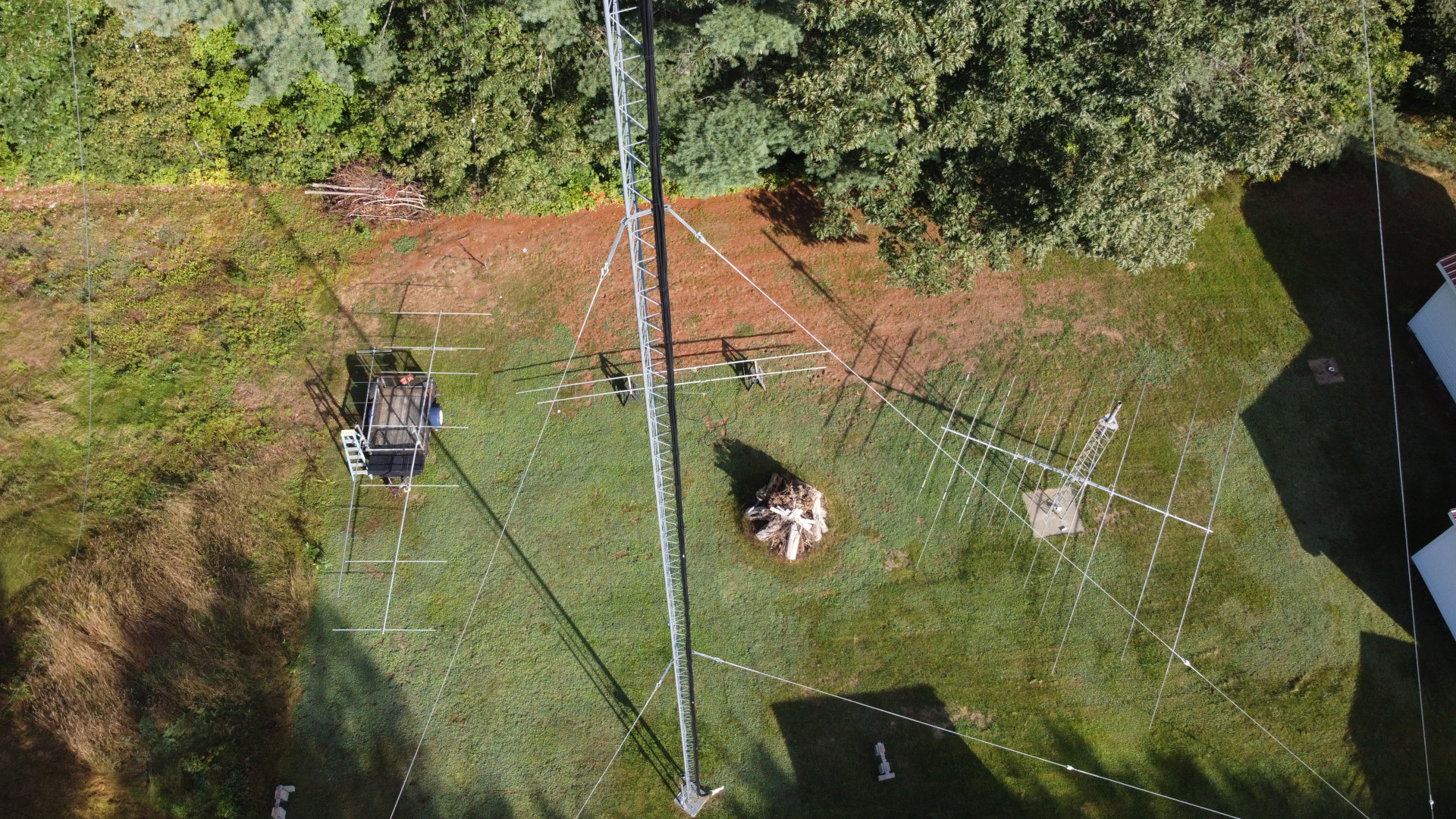
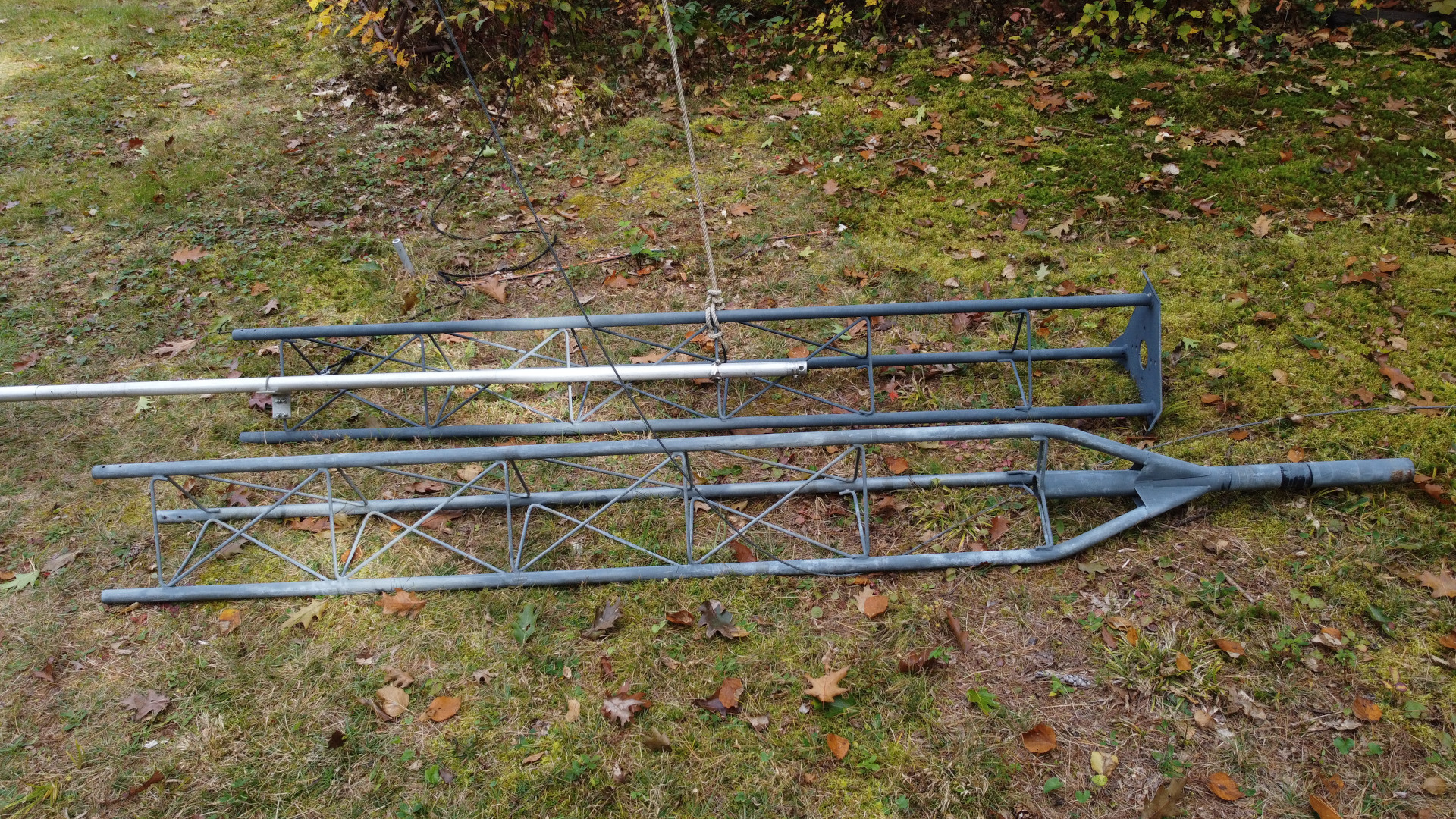
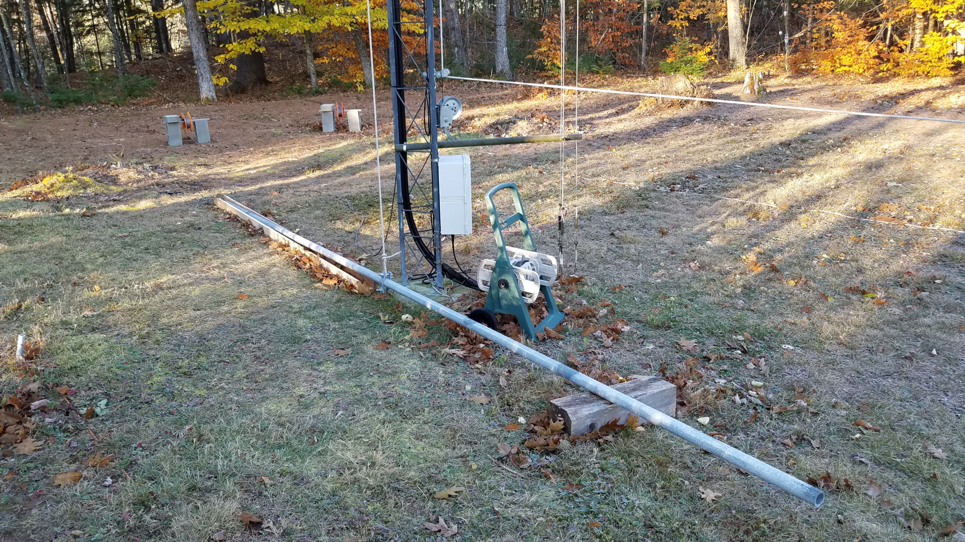
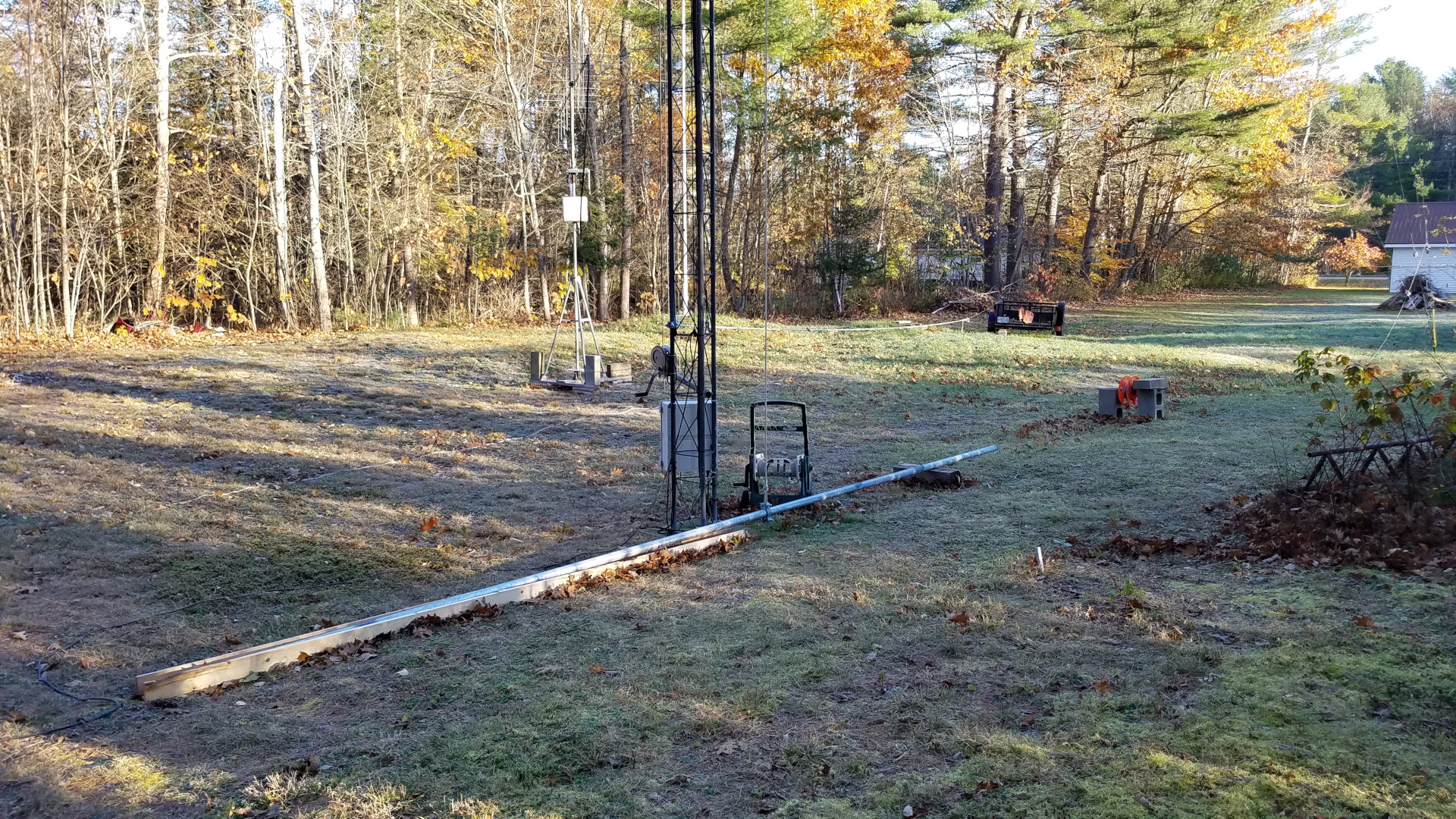
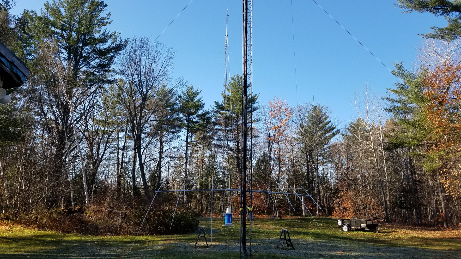
Now it was time to get to work on repairing the southwest tower. I added a temporary set of guys 10 feet down from the top and lowered the regular top set. The first challenge was removing the old mast and rotator. I had to hammer things apart and beat the mast out of the Rohn 25 pointy top section with a sledge hammer! That’s a lot of fun 100 feet in the air. Replacing the tower top section required some special rigging. I had LDF5-50A, 0.84″ CATV line and rotor cable all running up the inside of that tower! There was no way I was going to dig those buried cables up and pull them out of the tower if I didn’t have to. I couldn’t replace the top section using a standard 12 foot gin pole because it lacked sufficient height to lift a tower section straight up and free of the cables. I made a long gin pole out of a 20 foot section of 2 inch 6061 schedule 80 aluminum pipe and mounted it across two tower legs with pieces of 2 inch by 2 inch by 1/4 inch thick galvanized steel angle. As with all tower section lifts, I used a counterweight on the rope below the gin pole to take most of the weight of the section. I attached a length of 1.5 inch OD 1/8″ wall aluminum tube to the braces of the tower top section to act as a lever/handle so I could push it up and off the cables. This worked out pretty well, and the new stop section was rigged the same way for going up and over the cables. In the interim since the tower was first installed I had managed to acquire a 25AG4 flat top section which is far more desirable than the pointy top. After getting the top section replaced, the permanent guys were put back in place and the temporary set removed.

The old top section rigged for removal.
The tower without a top section. Well, that looks a bit odd!
Old top section and the new one rigged for raising.
New top section in place.

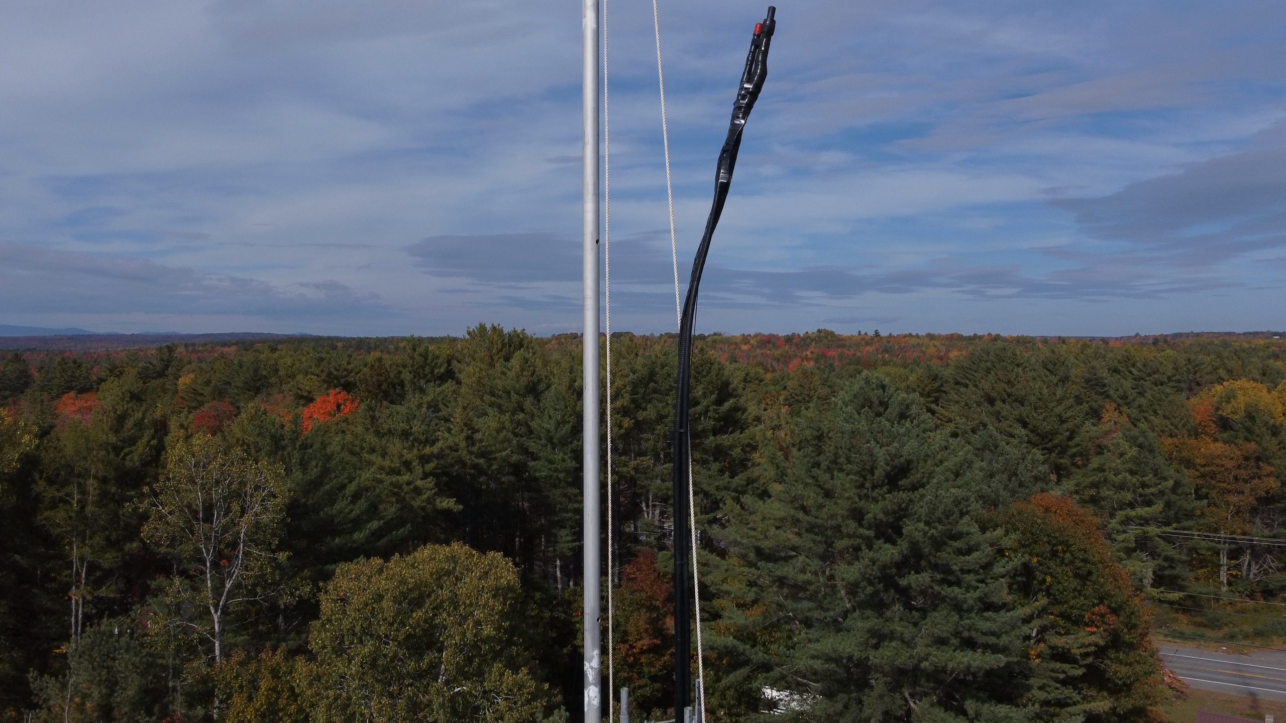
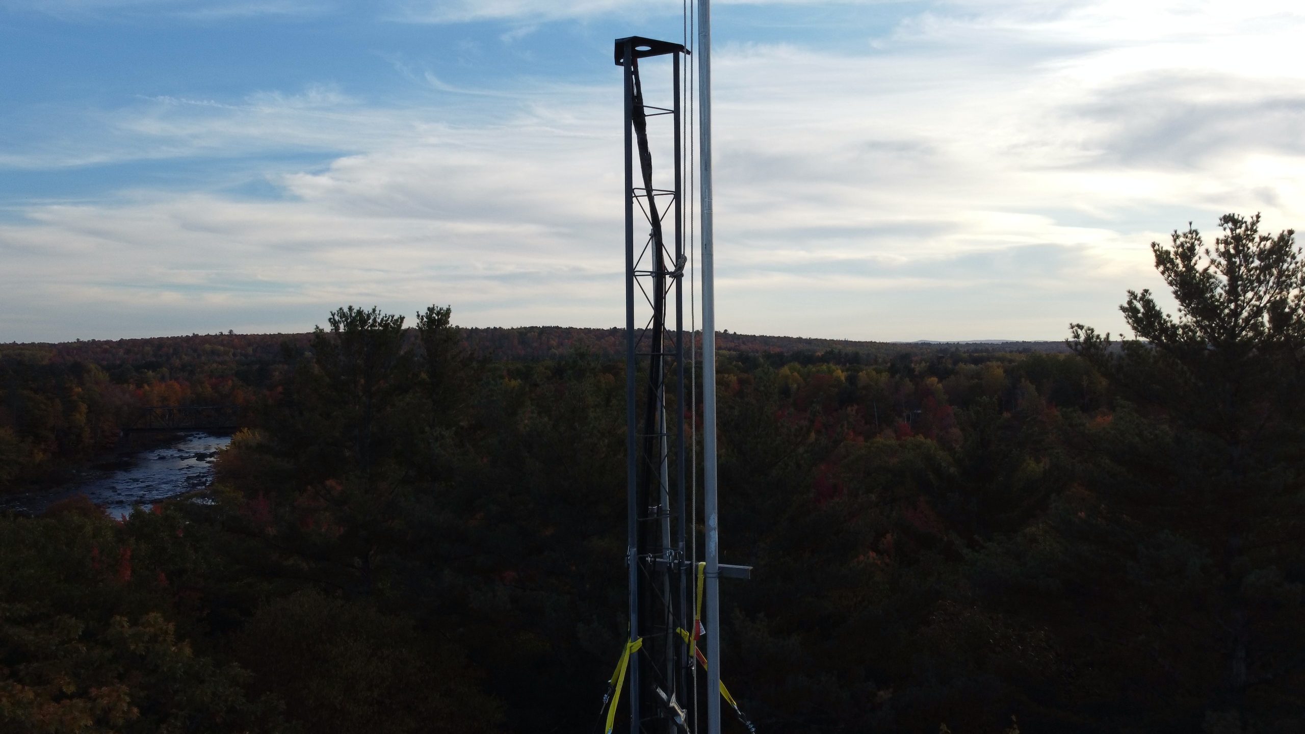
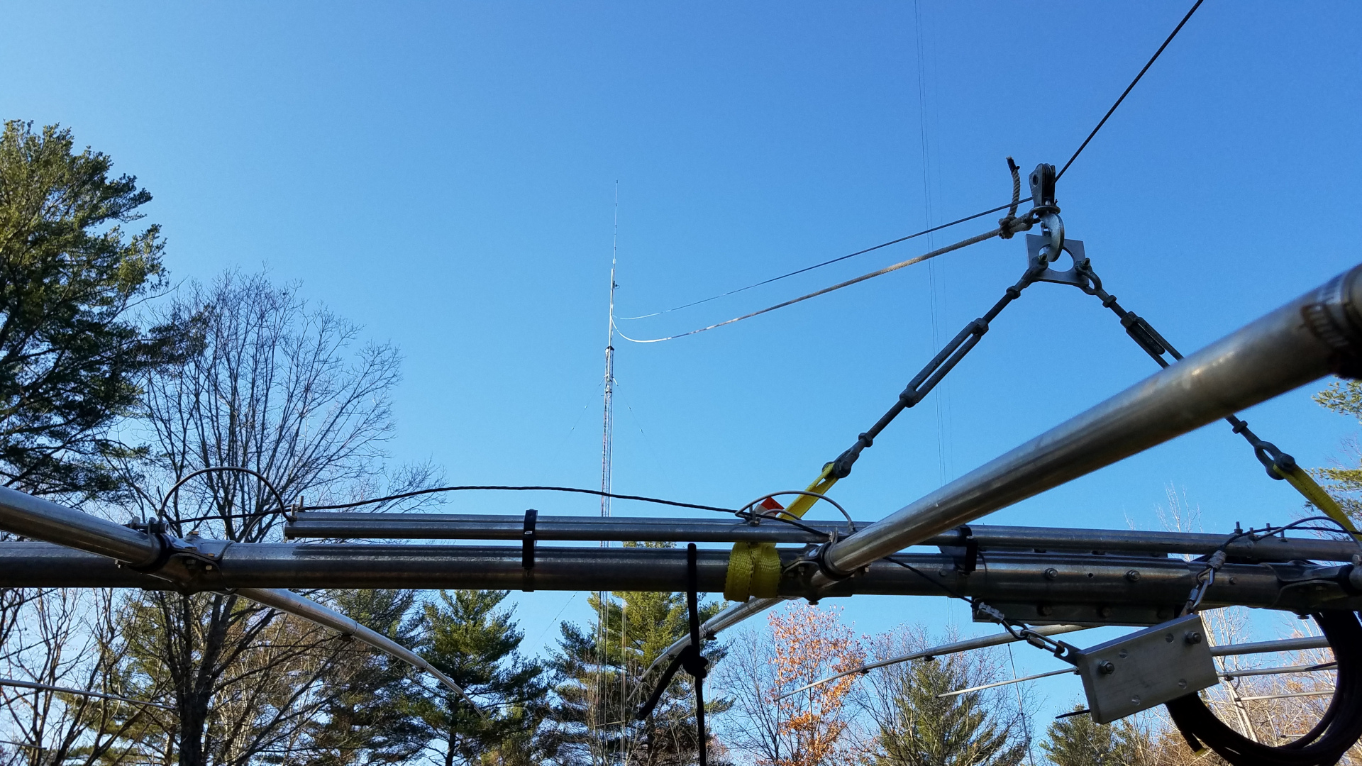
I mounted a proper thrust bearing on the tower top, and put an accessory shelf at the bottom of the 25AG4 for the rotator. In between another accessory shelf was fitted with a centering bearing made of Acetal plastic. I used DX Engineering shelves and I must say they are far better than Rohn shelves! The top bearing is also a DX Engineering product. The next task was getting the new 22 foot long 4130 chromoly mast into place. Weighing 125 pounds it was going to be a challenge for me. I once again used the long gin pole to good advantage. Instead of using counterweights, I rigged a worm gear winch to haul the thing up. This was the one thing I did have help with for about 10 minutes. I hauled the mast up until the top of it was inches below the top of the tower, then had a helper run the winch while I was on the tower for the last 23 feet of lift and dropping the mast into the tower.

The mast ready to be raised.
A different view of the mast raising setup.
Tower top rigging for mast raising. From this angle, it doesn’t look like a 20 foot gin pole.
The winch used for mast raising.
Winch mounting. Well, it did work…
The mast is in!
The gin pole has been removed.

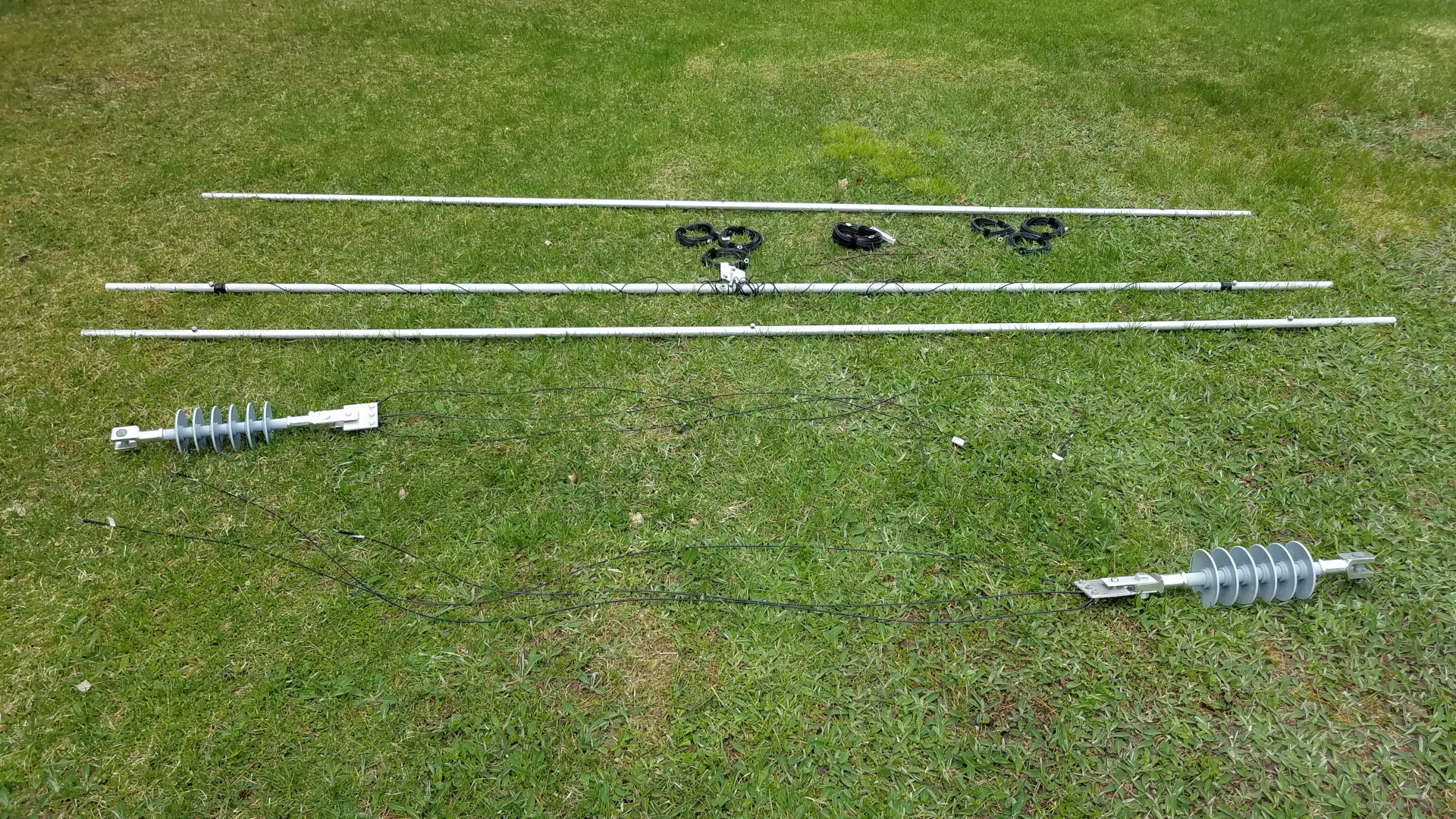
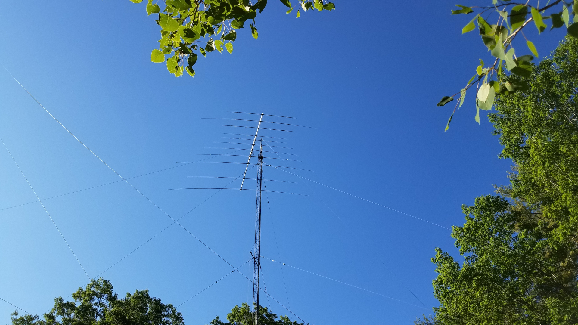
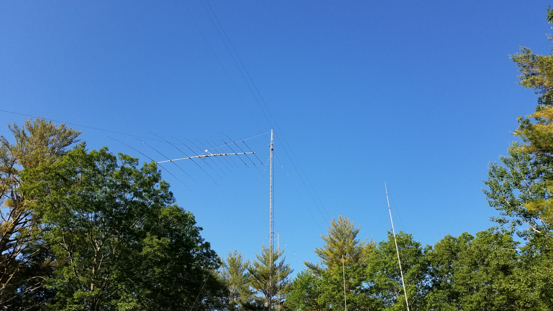
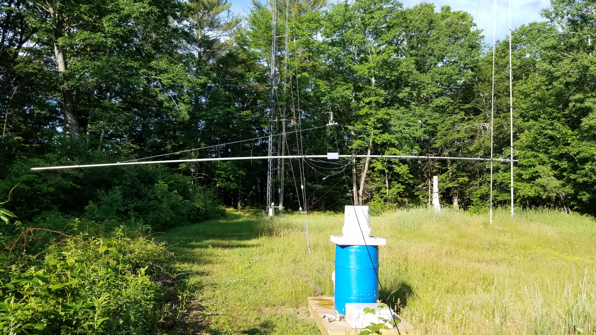
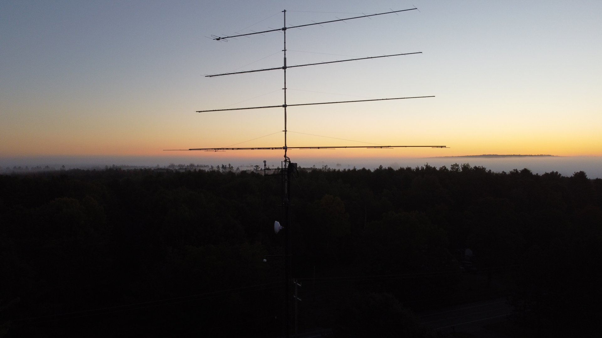
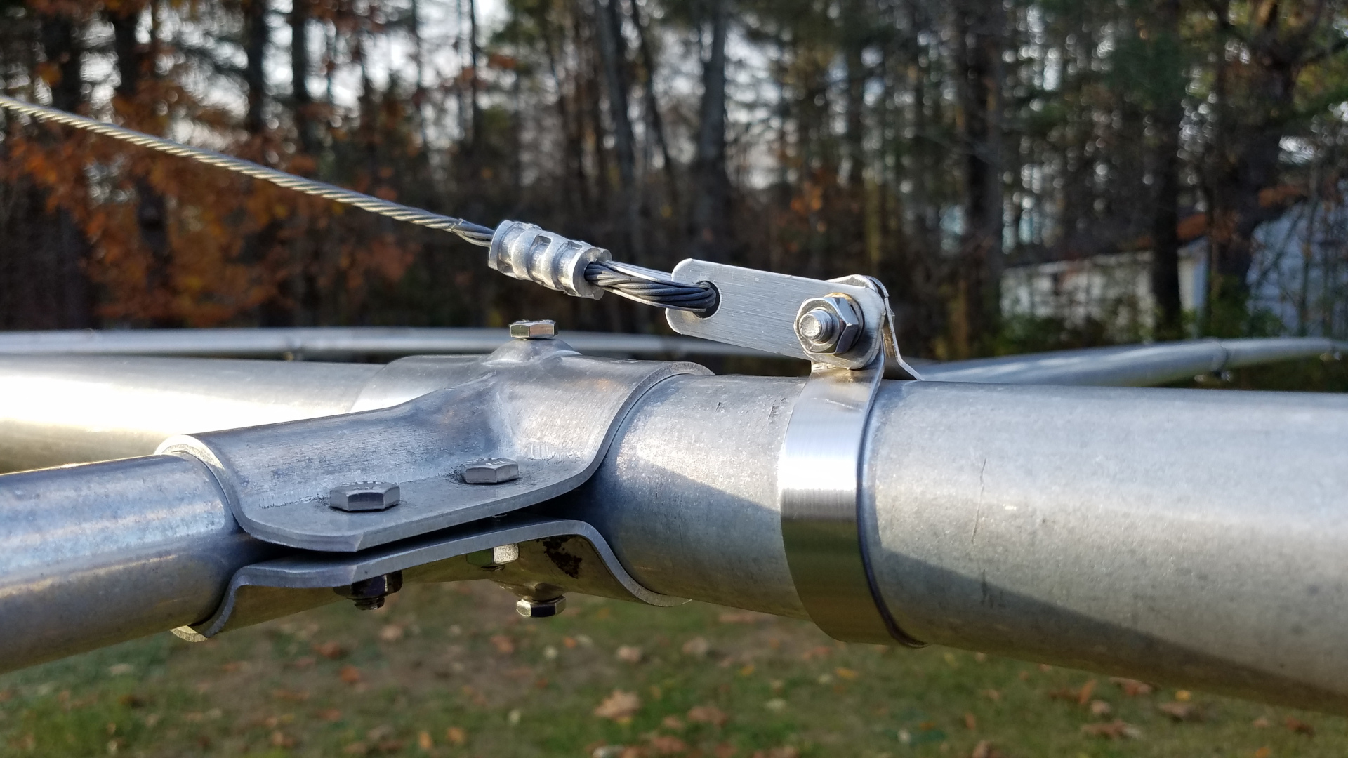
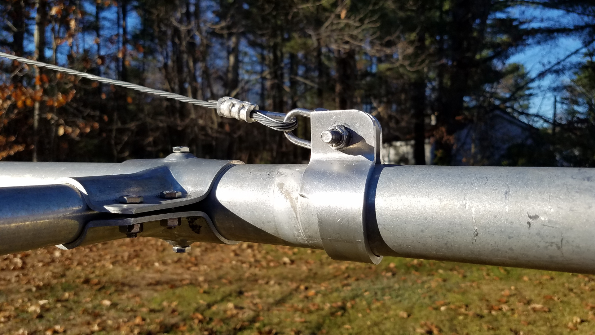
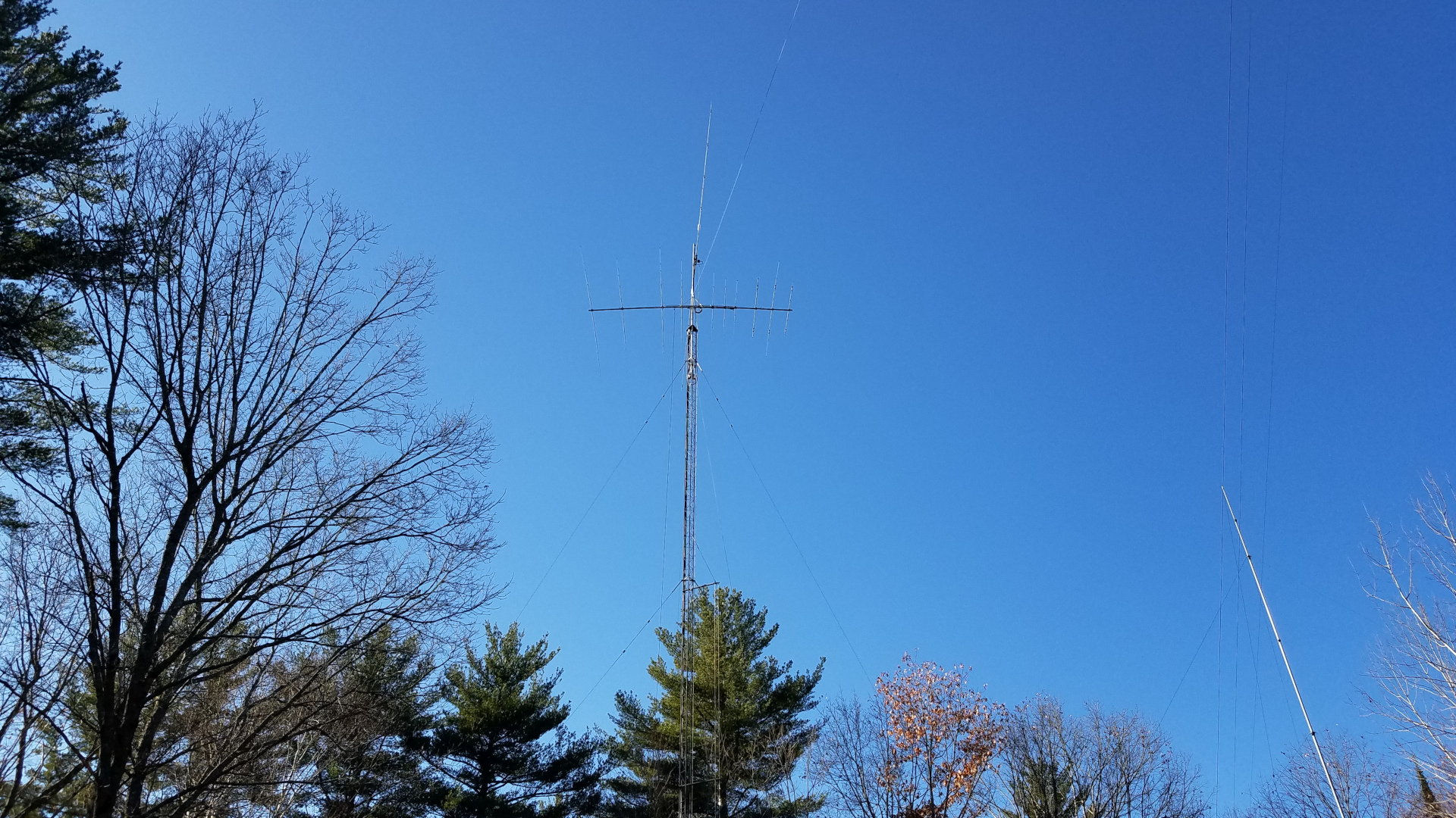
I did manage to sneak an upgrade into the rebuilding effort. I acquired an OptiBeam OB1-4030 rotatable dipole to replace my 40 and 30 meter inverted V antennas that always seemed to have me struggling to work the DX, let alone struggling for contest QSOs. I had been hearing that a dipole beats an inverted V at the same height, so I decided to try this after two failed attempts at home brewing a two band rotatable dipole in recent years. Besides, I was on a campaign to eliminate as many wire antennas hanging off the towers as possible. Skipping ahead, it turns out the improvement is nothing short of incredible! My 40 meter inverted V was at 104 feet, 30m at about 90 feet. The OB1-4030 is at 108 feet on the other tower 145 feet away. I was able to leave the old antennas in place for a while to make comparisons. The OptiBeam beat the inverted V antennas by margins ranging from 5 dB to more than 35 dB depending on the station and time of day! Every time! I have done extensive comparison using the Reverse Beacon Network. I have also experimented with calling DX stations many times with the old antenna and then the new one. Often they continue to CQ while I call time and again with the old antenna but I work them on the first or second call with the new one. I can work DX I never could before and get a much better run going in a contest. This is just amazing! Most of the time I found I no longer needed Beverages for receiving on 40 meters. The exception being during multipath conditions where the CW was difficult to copy. Then the Beverages still provide advantage.

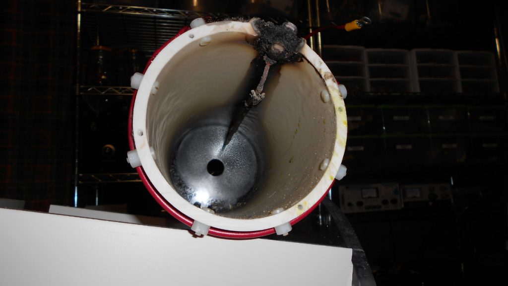
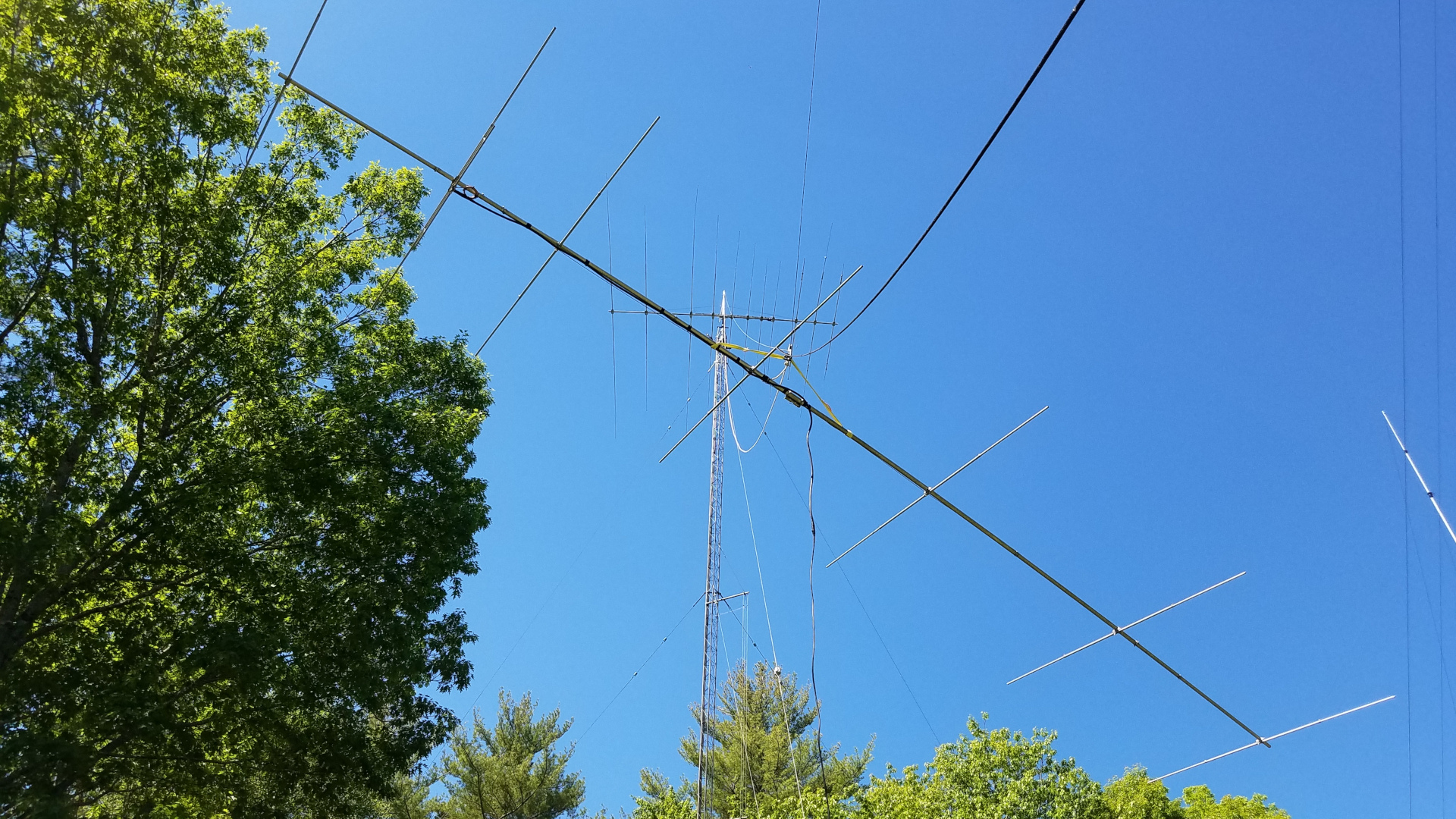
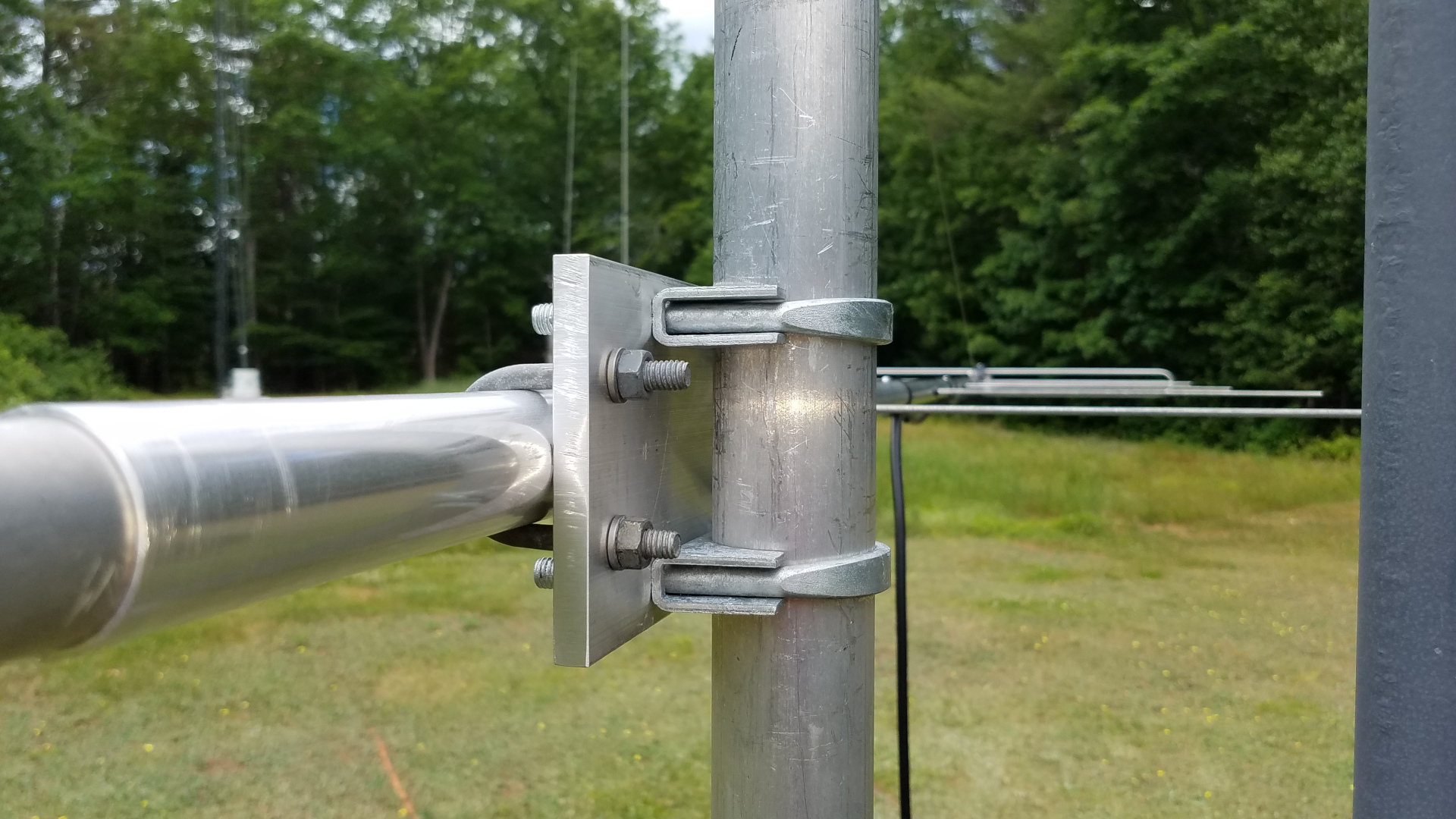
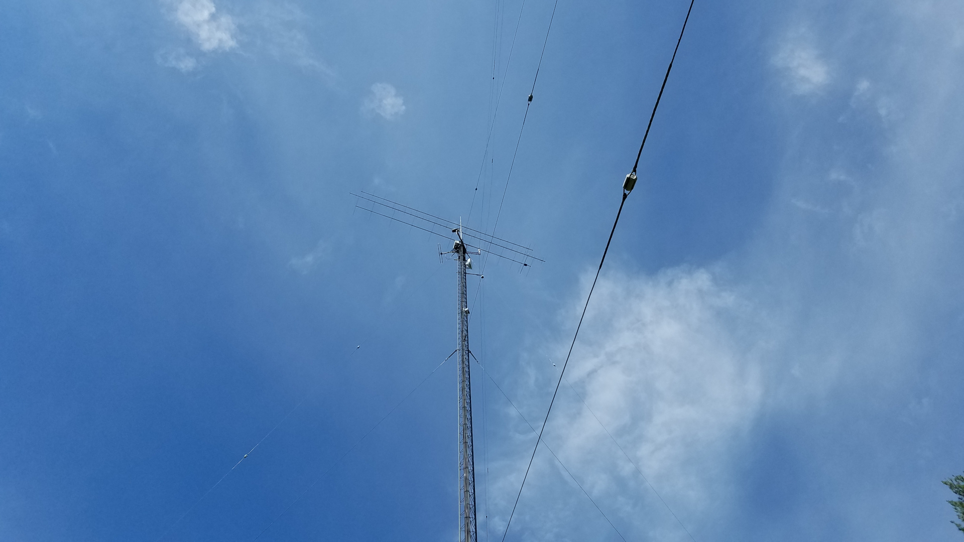
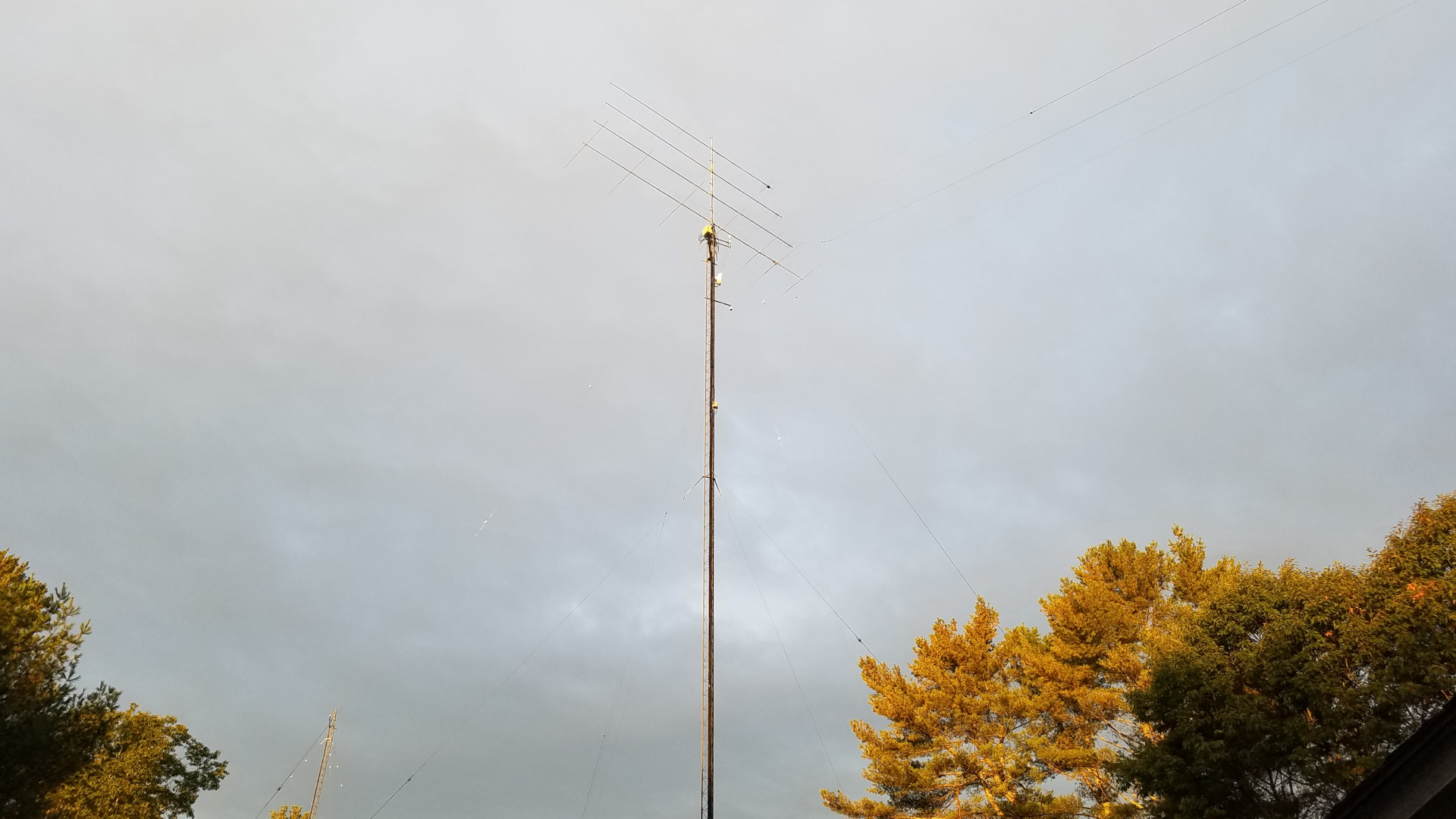
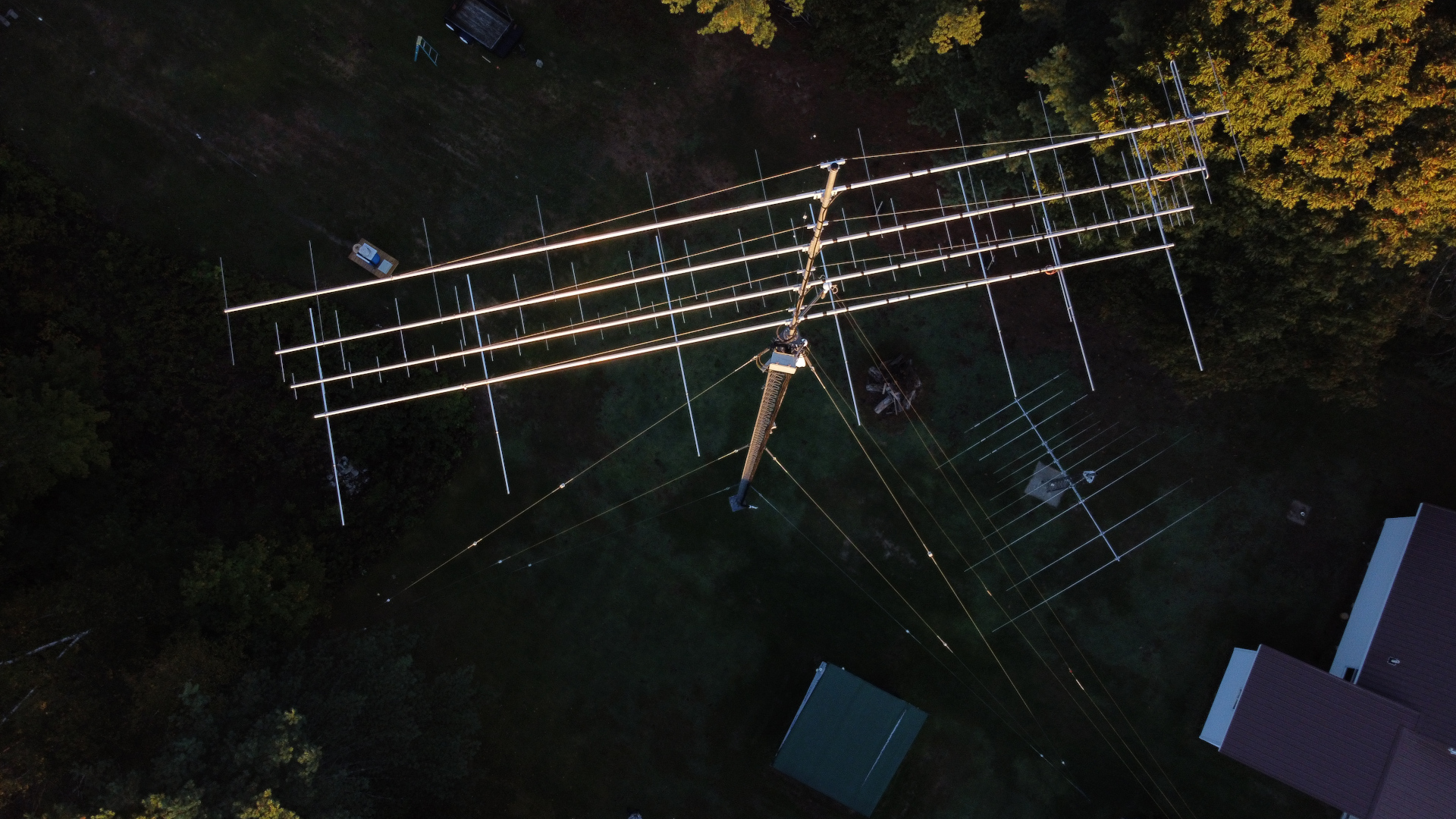
The TH11DX needed more attention than any other antenna. The traps were taken apart, modified with additional screws to reduce wobble, shattered trap caps were replaced and covered with 3 layers of Super 88 vinyl tape, element tips were straightened, coax replaced and the ridiculously inadequate boom truss hardware was replaced with something more reasonable.

Original TH11DX truss to boom clamp. Seriously, MFJ/HyGain?
Truss to boom clamp replaced with a DX Engineering part.
The original TH11DX truss to mast clamp, which had broken after only one year of service and had to be patched up on the tower. It was nearly ready to break again. Ridiculous.
The new home made truss to mast clamp.

Six years ago I struggled to tram the TH11DX up working alone. I did it by hand, wrapping the pull rope around my waist, leaning back and walking backward for the pull. I was pleased to see that now, at the age of 58 I can still do it, and somewhat easier than the first time. That’s odd but I’m not complaining!

TH11DX on the tram line.
Another view of TH11DX on the tram line.
Closeup of rigging for TH11DX tramming.
TH11DX at the top of the tram line.
Final installation, TH11DX at 98 feet, OB1-4030 at 108 feet.

I was concerned about interaction between the TH11DX on 15 meters and the OB1-4030. I had chosen to start without a 90 degree offset to see what happened. I see no detrimental affect. The TH11DX still has a good pattern on 15 meters (and all other bands), SWR is fine, and from what I can tell it is working as well as it has all along. I got away with it!

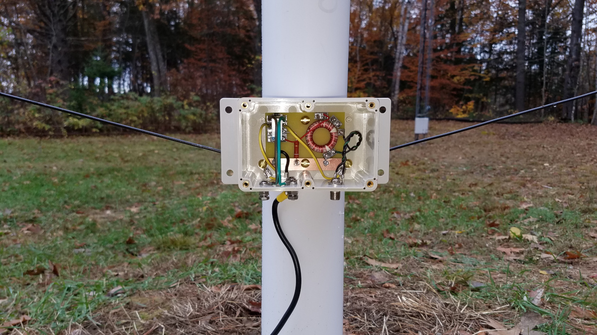
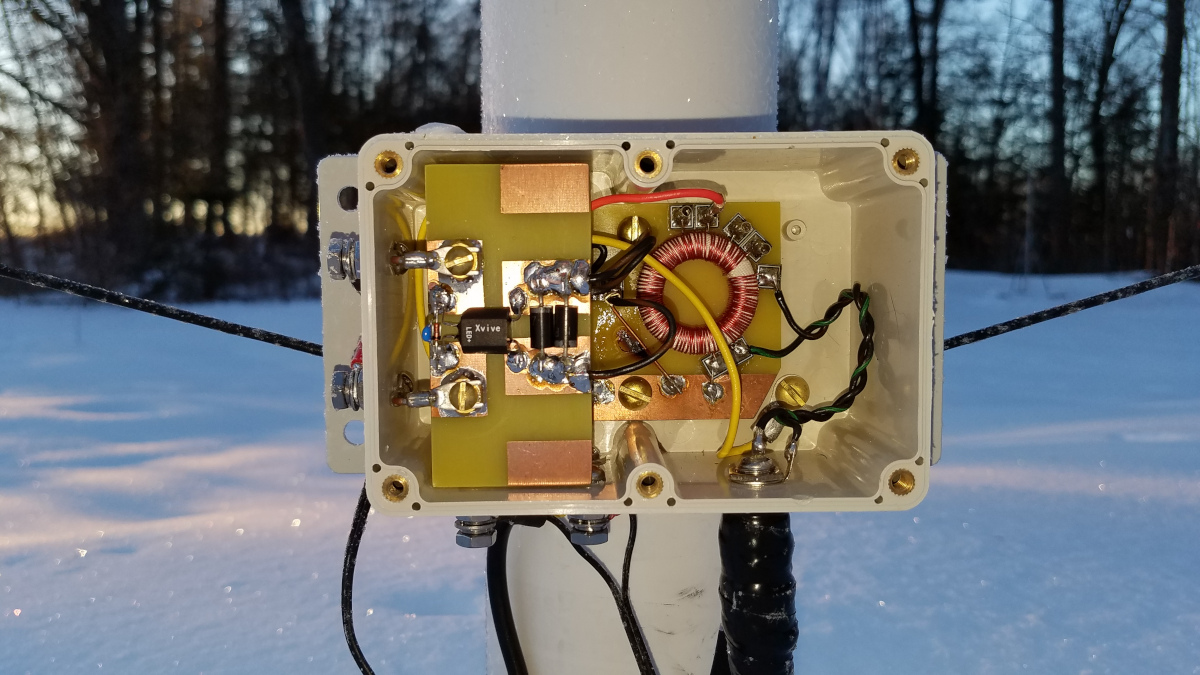
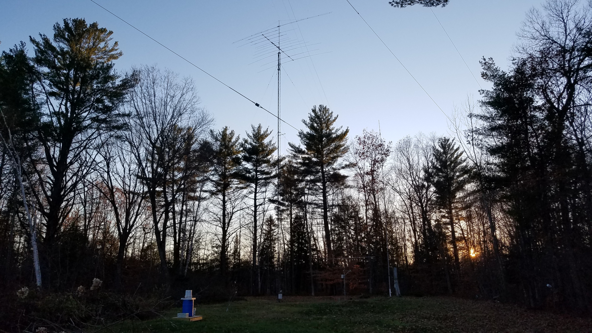
The last of this work was completed with snow on the ground. As of December 2021 I still have some work to do on low band receive antennas which have somehow managed to develop issues during the a period of disuse. Other than that, all damage has been repaired. 160 meters through 70 cm are back up and running. The loan was a necessary evil but unfortunately it means very limited new projects for a while. During the course of this project, May through December, with great effort and force of will, I was able to lose 40 pounds. By the end of the project my comfort climbing was as good or better than it has ever been.

First USA to Europe Amateur Radio 2200 Meter QSO

This is one of a series of “Notes” I published on Facebook. Since Facebook has discontinued the Notes feature, I am publishing that series here on my blog.

It was early morning on the 28th day of March, 2018. Most people were sound asleep but not me. I was in my ham shack, hands trembling, heart pounding as I typed a few letters and numbers into my logging program. I could barely breathe. I had just completed one of the most exciting QSOs of my nearly four decades chasing DX. This single QSO cost more money and time than any other I had ever made. It was a QSO with England. You may wonder what is so exciting about that when any ham with five watts and a piece of wire can contact England from Maine. Well, this was special because we did it on the 2200 meter band. It was the first amateur radio USA to Europe QSO on what is, for us, a new band. This was no easy feat. It required months of station building and four nights just to complete the QSO. Some would call it a ridiculous folly and see no sense at all in it. But to me this is the true spirit of amateur radio, finding a way to communicate against the odds, adapting equipment and technique to accomplish the desired result. It is man and his machine against nature, determined to succeed under the most difficult circumstances.

The 2200 meter band allocation is 135.7 to 137.8 kilohertz in the long wave part of the radio spectrum known as LF or low frequency. In some ways this goes back to amateur radio’s early roots on 1750 meters, but it had been more than 100 years since U.S. amateurs were allowed to transmit in this part of the radio spectrum. These frequencies are not easy! Normal size antennas would be huge. A half wave dipole would be 3400 feet long; a quarter wave vertical towering to a height of 1700 feet. Natural and man made noise tend to be very high in this part of the radio spectrum and ionospheric propagation is feeble compared to the short waves. On top of that, we are only permitted to run one watt effective isotropic radiated power (EIRP). That is flea power compared to what we can use on most any of our higher frequency allocations! By comparison, when I was doing EME (moonbounce) on the two meter band I was legally running about 450,000 watts EIRP. But ham radio DXers who like a good challenge can be a very determined lot. The greater the challenge, the greater the reward.

I became interested in 2200 meters in late 2016 after the local club asked me to prepare a report on this and the 630 meter band, which were expected to soon be opened for amateur radio use in the U.S. At that time the only way to legally transmit on either band was to get a Part 5 FCC license under the experimental radio service. One could almost write one’s own ticket on power limits and frequency allocations but this wasn’t amateur radio. I did apply for and was granted a Part 5 license but never used it since FCC opened these new bands to amateurs just as I was getting a station put together. I found receiving on 630 meters to be relatively easy, if somewhat plagued by noise and available antennas. But 2200 meters was a very different thing. It took weeks of experimentation and testing to detect the first trace of signal on this band. Many weeks later after more trial and error I was rewarded with my first reception of a ham radio signal from Europe on the band when DC0DX appeared in my WSPR decodes. I confess it was then that I first started to dream of someday making a two way QSO across the Atlantic on long wave.

I thought I had plenty of time to build a station, since the FCC process on opening these bands had been dragging on for years. But in the Spring of 2017 the announcement came that we would get these new bands in a few months! Now the race was on. I frantically began building transmitting apparatus. I didn’t quite make it for opening day in October but I was on the band a few weeks later. Early amplifiers were plagued by budget shortfalls and poor performance. By mid February, 2018 I had managed to achieve 0.5 watt EIRP, just three decibels below the legal limit. The flood gates opened and to my amazement I started receiving numerous WSPR decodes from European stations. Wow!

I believed a two way trans-Atlantic QSO was in my future but was not sure when. I was eager for an attempt but still very much struggling with equipment and budget. I was hearing stations from Europe. Stations from Europe were hearing me. But for the most part, those who heard me did not have transmitting capability or not sufficient to reach across the Atlantic. The best bet would seem to be 2E0ILY. We had conducted tests earlier in the season and I could often copy his JT9 beacon. Chris could occasionally copy my WSPR signal but not at sufficient strength for JT9 to be viable. I knew there were ways to get it done, but this would take several nights. I was hesitant to ask anyone to commit such effort and time to a QSO.

As the relatively quiet season was drawing to an end I realized another season is never guaranteed for any number of reasons. I had given the matter considerable thought. There were no practical digital modes which would work with the low signal levels involved. Two old school modes came to mind: QRSS and DFCW. Both are very slow, trading time for weak signal detection capability. QRSS is extremely slow CW, so slow in fact that it can only be copied by reading it off a computer screen. In this case, a speed of QRSS60 would be best, meaning that each dot would be 60 seconds in duration. A dash is three times as long, just as in normal CW. This mode requires nothing special for equipment, as it uses on/off keying of a carrier and is fairly tolerant of frequency drift. But, the shortest element, the dot, sets the achievable signal to noise ratio. There is no advantage gained from the dashes being three times as long, so it is essentially time wasted. Time is valuable, as signal fading means you have a limited amount of time to copy the message. DFCW, or dual frequency CW is an offshoot of QRSS in which dots and dashes are the same length but sent on slightly different frequencies so that one may be differentiated from the other. This saves considerable time with no reduction in signal to noise ratio but requires more complex transmitter keying and reasonably tight frequency stability. In a typical DFCW60 transmission, the dot to dash frequency shift is a small fraction of a hertz. Transmitter and receiver drift must be held to less than this in order to avoid dot-dash ambiguity at the receiving end. It would take about an hour to send two call signs at DFCW60 speed. It was now late March. Clearly there would not be enough common darkness between Maine and any part of Europe to allow a QSO to be completed in a single night at this speed.

It may be useful to consider what is a QSO. These days the term means different things to different people. I came up through the DXing ranks with what is now a somewhat old school definition for a minimum acceptable information exchange to claim a QSO under very weak signal conditions. I still firmly believe in the old way, as we are after all supposed to be communicators. That definition is that each station must receive from the other both call signs, signal report or other piece of information, and acknowledgment. This requires that two transmissions be copied in each direction. Anything less than that does not seem like communication to me, and leaves me with no sense of accomplishment.

It seemed the best way to go about it would be to borrow operating and reporting techniques from EME, modifying procedure slightly to account for the much longer period of time required to send a message on the long waves. In this procedure, the letter O would be used as a signal report to indicate full call signs had been copied; R and O would be used to indicate full call signs plus signal report had been copied; R by itself to indicate call signs, report, and R (as part of R and O) had been copied. As for timing, it seemed sensible to use night by night sequencing. That meant the two stations would take turns transmitting, one going the first night the other the second, alternating back and forth throughout the QSO. It would take a minimum of four nights to complete a QSO, assuming the full message could be copied each night. If it wasn’t, additional nights would be required for repeats. That’s really slow! But it did offer some advantages with the equipment available. In order to achieve the required frequency stability I would have to use my QRP Labs Ultimate 3S beacon transmitter. The U3S is a great piece of gear, but editing messages is tedious. Night by night sequencing would give me all day to change the message for the next night’s transmission! A complete QSO would look like this, where bold indicates my transmissions, italics indicate transmissions from the other station:

2E0ILY N1BUG
N1BUG 2E0ILY O
RO
R

Meaning of the first line is obvious. I am transmitting both call signs. In the second line my QSO partner adds the signal report, O, to let me know he had copied both call signs fully. In the third line I send RO which means I have copied call signs and my report, your report is O. In the last line my QSO partner sends R, meaning I have copied all on my end. When I copy the R the QSO is complete. If a message is not copied, or not enough information is copied, then one continues to transmit the previous message until getting something back which advances the QSO.

I had worked out a viable technique. Now I just needed a QSO partner. Just in time I worked up the courage to ask Chris, 2E0ILY if he would be willing to give it a try. I was very happy when he said he’d have a go at it.

We had decided I would transmit the first night, so I set the U3S to send ‘2E0ILY N1BUG’ over and over during the hours of common darkness between our respective locations. It turned out to be an ugly night in terms of weather. I was getting heavy wet snow squalls. Nothing causes a 2200 meter Marconi antenna (vertical) to go out of resonance any quicker than wet snow! These antennas are electrically short and require huge loading coils to resonate them. They are high impedance antennas and the bandwidth is very narrow. These antennas are prone to changing characteristics on a whim. Every time the snow started, stopped, changed intensity or the amount of snow clinging to the antenna changed, the thing went wandering up or down the band and required retuning for resonance on the operating frequency. Fortunately the variometer at the antenna base was motorized and I could adjust it from the comfort of my transmitter room. But I had to keep a constant vigil, watching antenna resonance and adjusting as needed. I had my finger on the switch for variometer adjustment far more than not. After a while my fingers were getting sore from constantly manipulating the tuning switch. Perhaps I shouldn’t have used a miniature toggle switch there. If you think this was an automated QSO without operator involvement, think again! My presence and diligence at the controls was absolutely vital that night!

Message copied from 2E0ILY on the second night of the QSO (annotated). Note dots on the lower frequency, dashes shifted 0.187 Hz higher. When the signal is this strong, elements tend to bleed together a little but since they are of fixed length it is still very readable.

The next night it was my turn to listen. Due to the extremely slow speed DFCW is copied visually using software designed for this purpose. Anxiously I stared at the screen. When I wasn’t nervously pacing, that is! I began to see traces of signal, then an odd letter here and there. There was a B, a 2, a Y and I even thought I saw an O but couldn’t be sure. Eventually conditions stabilized and I began to get steady print on the screen. Waiting 60 seconds for a dot or dash to fully paint on the screen can be agonizing. Slowly the elements accumulate and become characters. If you are lucky, propagation holds up long enough to copy the full message. Fortunately, after somewhat of a slow start copy remained solid and I eventually had N1BUG, 2E0ILY and a very nice O painted on my screen! I had copied full call signs and a signal report indicating Chris had got full call signs from me the previous night! We were half way there!

The third night I was transmitting again. Since I knew Chris had already copied full call signs from me, it was not necessary to transmit them at this stage of the QSO. Technically I could have just sent RO repeating throughout the night, but being of the cautious type I decided to include call sign suffixes to provide positive evidence the correct station was being copied. Thus the message I transmitted was ‘ILY BUG RO’. This was a risk as it takes far longer to send than simply ‘RO’ and signal fading can be a huge factor. At least the weather was better and I didn’t have to ride the variometer all night.

Soon it was night four, back to pacing and staring hopefully at the screen. I was especially nervous that night, as I had some strong, drifting interference right on top of Chris! Finally it moved just enough that I could make out ‘BUG ILY R’. There was rapid fading and the dash in the R was much fainter than the rest. Fainter but unmistakably there. I was positive about the R but being the cautious type and realizing this QSO would be an amateur radio first I really wanted to see it more clearly before declaring the QSO complete. The signal faded and nothing was seen for hours. Sunrise at 2E0ILY was fast approaching and I had to make a decision. Was I going to log the QSO or retransmit my RO message the following night in hope of getting better copy of the R on night six? Just before dawn the signal reappeared, very weak. I could barely make out ‘BUG IL’, then the ‘Y’ was quite strong. Given the proximity to sunrise every minute felt like an eternity. Ticking of the clock became offensively loud. It was going to take another four minutes to get an R! Would it hold up that long? Slowly, as the clock ticked and my heart raced, a crystal clear ‘R’ painted on the screen. There were traces of signal for some time after that but nothing I would call readable, save a stray ‘Y’ that somehow came through well past dawn. So it came to be that shortly after 0600 UTC (1:00 AM local time) on this, the 28th day of March, 2018 I entered this QSO into my station log. We had done it!

QSL card received for this very memorable QSO!

This was an amateur radio first from the U.S. but nothing new in terms of distance on the 2200 meter band. Canadian stations, operating under amateur call signs but otherwise a program similar to our Part 5 licenses, had worked Europe years earlier. Much longer distances had been covered. But for me this was one of the most exciting QSOs of my nearly 40 years as a DXer. It ranks right up there with my first EME QSO, the QSO that put me on the DXCC Honor Roll and several other notable events such as being credited with the first North American two meter auroral E QSO back in 1989. My thanks to Chris, 2E0ILY for his time and patience to make this happen – not to mention the kilowatt hours of electricity expended.

DFCW may be old school but it gets the job done under extremely difficult conditions. DFCW ‘decoding’ is done by the human operator. Deciding what has been copied is not left to computer software which may use assumption or non amateur radio means to fill in things it couldn’t positively make out over the air. DFCW is painfully slow but here we had a very positive over the air exchange of full call signs, reports and acknowledgement without any shortcuts or fudging. I was very pleased with that!

Although this single QSO cost more than any other, this was a low budget operation. Most of the LF station consists of low cost kits and home built gear. Equipment used at my station for this QSO was the QRP Labs Ultimate 3S driving a home built amplifier to 175 watts output. The transmitting antenna was a 90 foot Marconi (vertical) with a top hat consisting of three wires each 100 feet long, spaced five feet apart. Three one inch diameter aluminum spreaders plus triangular wire sections at each end are electrically part of the top loading. This is resonated at the base with an inductance of approximately 2.3 millihenries. Loss resistance at the time was near 100 ohms, resulting in EIRP of 0.5 watt. For receive I used a 30 foot low noise vertical, band pass filter, W1VD preamp, and a modified Softrock Lite II SDR receiver.

My First Night “High Power” WSPRing on 630 Meters

This is one of a series of “Notes” I published on Facebook. Since Facebook has discontinued the Notes feature, I am publishing that series here on my blog.

I have been listening on 630 meters for over a year and I had operated a WSPR beacon two previous nights with very low power of about 15 milliwatts EIRP (Effective Isotropic Radiated Power). Even at that power level I was heard by more than 25 stations at distances to beyond 1000 miles, 1600 kilometers. But last night as winter descended upon the region with the first significant snowfall, I was transmitting with 22 watts TPO (Transmitter Power Output), resulting in about two watts EIRP. That is still four dB below our legal limit of five watts EIRP. Results were better than I expected for my first night, even though propagation was certainly not at its best!

At times I am a rabid contester, an avid DXer, an experienced builder of antennas and equipment. I love radio. I enjoy all of these activities but if I had to describe my pursuit of radio in one word it might be explorer. I love trying something new, venturing into little used territory, pushing limits, trying to beat the odds. I have a well equipped station. I could easily converse with amateur radio operators around the world most days just by turning on a radio and speaking into a microphone. Instead I am driven to pursue nearly impossible contacts on frequencies that do not easily go the distance. I especially enjoy pushing the limits of propagation, equipment and myself as an operator on modes where the human ear/brain is the decoder. Unfortunately that is becoming a rare thing in today’s world of digital modes where the computer does the decoding, all too often using only partial information received over the air, the rest filled in from a database or assumed because it was information previously known to the decoder. The continuing erosion of what represents a two-way amateur radio contact saddens me beyond words. Nevertheless I continue to find joy and excitement in the exploration of frontiers which, if not new to mankind, are new to me. I regret only that there will not be enough time to explore all there is to see and do in radio.

So it was that little more than a year ago I began my quest to conquer the two new low frequency bands, 630 meters (472 to 479 kHz) and 2200 meters (135.7 to 137.8 kHz). I spent the first winter learning about and building receiving equipment for those frequencies. There was a learning curve and I had to find what worked within my budget. Mission accomplished.

In the Spring I set my sights on building a transmitting station but quickly ran into a setback. The only way to put up a reasonably efficient antenna in the space I have would be to support it between my two existing towers. It didn’t take long to discover the older, weaker tower would not stand the strain of such an antenna! There was only one thing to do: replace the tower! The search for materials took all summer and the project wouldn’t have been possible at all without a great deal of help from friends. The work began in October and was not complete until the middle of November. That left little time before the onset of winter to build the antenna, a transmitter, and all the associated things that go with it. The antenna, a Marconi-T made of wire and strung between two towers, is shown in the cover photo.

One has to get into a very different mind set about antennas at these frequencies. Most of us are accustomed to “full size” antennas – dipoles, verticals, loops – which radiate nearly all the power we put into them. In many cases we use directional “gain” antennas that actually make our effective power more than we have coming out of the transmitter – in a favored direction. Very few if any will be able to reach anything approaching 100 per cent efficiency at 630 meters and no one will at 2200 meters. Forget about gain antennas! Horizontal polarization does not work well at these frequencies. A quarter wavelength vertical for 630 meters would be 490 feet (149 meters) tall and for 2200 meters, 1700 feet (520 meters)! Not only that, but unless located over salt water a vertical needs an extensive system of ground radials around it to be efficient. Most amateur antennas at 630 meters will radiate no more than a few per cent of the power fed to them, while many will be less efficient. At 2200 meters reaching one per cent efficiency will be very difficult for most, impossible for many. My 90 foot (27 meter) tall vertical with three 100 foot (30 meter) horizontal top loading wires sits over a radial system with more than 10,000 feet (3048 meters) of wire in it. Yet the best I can hope for is 3% efficiency on 630 meters and 0.25% efficiency at 2200 meters. The vast majority of power is eaten up by ground losses and losses in the large loading coils needed.

In fact, once we cancel out capacitive reactance due to the antenna being electrically short, the resistance we see isn’t really the antenna at all – it is dominated by loss resistance! Even at 630 meters the radiation resistance of a typical antenna will be an ohm or two, in many cases less. Even very good ground systems will be many ohms. My radiation resistance on 630 meters is 1.25 ohms. I measure 39 ohms when the antenna is resonant. Almost all of that is the ground system loss resistance, and that is where most of my power goes! This really is a different world from the higher frequencies.

The challenge doesn’t end there. After we manage to get a few watts radiated, we have to contend with the fact the ionosphere doesn’t propagate signals at low frequencies as well as it does higher ones, while both atmospheric and man made noise is much worse down here! It’s a wonder we manage to communicate at all. But we do. That’s the challenge, and that is what attracted me to this.

The variometer (left) is an adjustable inductor used to cancel out capacitive reactance in the antenna and resonate it on the desired freqeuncy. The matching transformer on the right steps up the resistance of the antenna system (in this case about 39 ohms) to the 50 ohm impedance of the feed line and transmitter.

By midday December 9 I was ready. The antenna was up, the variometer adjusted, matching transformer properly configured and my little 25 watt home made transmitter was ready to strut its stuff. I set it to transmit as a WSPR (Weak Signal Propagation Reporter) beacon, sending out a two minute standard WSPR message every ten minutes. In broad daylight, I received several reception reports after my very first transmission! WSPR reception reports are available on the Internet almost immediately and may be viewed as a list or displayed on a map.

The transmitter, consisting of a QRP Labs Ultimate 3S exciter (assembled from a kit) on the left and home made amplifier on the right.

I spent the first few hours nervously checking the transistor in the amplifier with my finger to see if it was running too hot, watching squiggly green lines on the oscilloscope for any sign the antenna was drifting off frequency or something breaking down outside. To my joy all continued to look good! It was not as if I had no reason to wonder. One transistor had died weeks earlier during initial testing of the transmitter. That occurred while running into a perfect resistive load, not an antenna that might be imperfect or change on a whim. These low frequency antennas which are, of necessity, electrically short actually can change on a whim! The capacitance and hence resonant frequency can change as they sway in the wind. The resistance can change with weather and season. With several inches of snow forecast for the night, I didn’t know what to expect. So I nervously watched over the system. After every transmission I checked to see where I had been heard.

As sunset approached and passed, the band naturally stretched out. I began to get stronger signal reports and was being heard at ever greater distances. After some time there was a report from a station in the Netherlands! My puny signal had made it all the way across the Atlantic on a frequency below the AM broadcast band! This was soon joined by reports from the Cayman Islands and Canary Islands. Africa! Toward morning I even got a reception report from Hawaii! Just before dawn I observed some variations in the antenna system. The two sine wave patters on the oscilloscope display began shifting slowly, almost rhythmically back and forth with respect to one another. This was caused by changes in antenna capacitance as it swayed slightly in a gentle breeze. I have heard the effect described “as if the antenna is a living, breathing entity” and I would have to concur with that description. It was fascinating to watch. I got very little sleep and didn’t even notice it was one of the longer nights of the year. I was having too much fun! I was exploring!

Oscilloscope patters from the “scopematch” monitor the antenna resonance and resistance. If the antenna were perfectly resonated on the transmitting freqeuncy and perfectly matched to 50 ohms these two sine wave traces would converge into one. Here, one is shifted to the left slightly, indicating an off resonance condition (in this case exhibiting inductive reactance), and they are not of the same amplitude (height), a sign of imperfect resistance match (here showing the resistance to be slighty high).

There are many challenges and new experiences yet to come on the low frequency frontier. One of my winter projects will be to build a transverter so that I can transmit modes suitable for two way contacts. But the bigger challenge is getting operational on the lower frequency band, 2200 meters. The coil and variometer will be much larger, creating not only issues in construction but in protection from weather. The antenna impedance will be far greater, resulting in very much higher RF voltage and the possibility of interesting but unwelcome events such as insulation breakdown, arcs and corona! Undoubtedly the antenna will “breathe” to a much greater extent. On 2200 meters I expect a lot of action on the scope when there is any breeze.

0 Comments

Exploring 630 and 2200 Meters: Part One

This is one of a series of “Notes” I published on Facebook. Since Facebook has discontinued the Notes feature, I am publishing that series here on my blog.

Back in September I was asked by an officer of the local amateur radio club to say a few words about our (hopefully) upcoming new bands: 630 meters (472-479 kHz) and 2200 meters (135.7-137.8 kHz). I didn’t have much to say. I hadn’t thought much about these bands. It might have ended there but for my interest in early radio equipment. Several weeks later in one of the antique transmitter building forums I saw a post about “630 Meter Crossband Night” which is an event held each November. During this event, several Canadian amateurs call CQ on 630 meters and listen for U.S. hams to call them on 160, 80 or 40 meters. These bands are already allocated to amateurs in Canada and many other countries. In the U.S. there are a number of stations operating with FCC Part 5 Experimental licenses. There is more than the usual CW activity among these stations on Crossband Night compared to other times. I figured I might as well give it a go and see if I could hear anything at all. As is often the case with me, A plus B equals hang on, we’re about to take a U-turn and go off on another wild adventure!

My station transceiver, a Yaesu FT-2000, has a general coverage receiver which tunes down to 30 kHz so I figured I would be all set there. I didn’t know if any of my existing antennas would work at this frequency. I have several Beverage antennas ranging in length from just over 500 feet to just under 700 feet. They work well on 160 meters but at 630 meters they are on the order of a quarter wavelength long. That is too short to work as a Beverage. At best I figured they might perform as random short pieces of wire oddly coupled to coax and the ground!

It didn’t take long to find my first signal on 630 meters: VO1NA in Newfoundland, Canada. Joe’s CW signal was excellent, several S units above the noise. I called on his 80 meter listening frequency and had a crossband QSO with him. Later I had a similar QSO with VE3OT in Ontario, a distance of over 600 miles. Clearly I could in fact hear something on this mysterious medium frequency band! I heard a number o the FCC Part 5 stations as well, including WG2XIQ in Texas. Unfortunately they are not allowed to communicate with stations operating in the Amateur Radio Service so crossband or any other form of two-way contact is not possible.

As for antennas, I discovered that I could hear several stations on my 80 meter inverted V and even one or two on my 20-10 meter beam. The Beverages were a clear winner though. Oddly I would discover that night and more so in the nights which followed that my west-facing Beverage had the lowest noise level of the eight directions available and was the best receive antenna for 630 meter signals from all directions. As for just what causes this, I don’t know. They are after all acting as short random length wires oddly coupled to coax and ground. There is no telling what the pattern is or how they might be interacting with each other or with other structures.

As a frequent user of the ON4KST internet chat site for low bands (160-40 meters), 6 meters and VHF/UHF (2 meters and up), I was aware Alain also had a chat page for the low and medium frequency bands. Naturally I checked in there to see who was doing what and get a better feel for activity. It didn’t take long to start assimilating the nature of the beast. It seems that in Europe, where amateurs in many countries have access to 630 meters, two-way QSOs are taking place on CW and various weak signal digital modes. There is also a lot of beaconing using WSPR (Weak Signal Propagation Reporter) taking place. In North America, since there are so few who can legally communicate with each other due to licensing issues in the U.S., the vast majority of activity is on WSPR. There is some CW and JT9 (another weak signal digital mode), and from time to time QRSS (extremely slow CW meant to be read visually from a “waterfall” on a computer screen). I began checking into the chat site every evening and it was immediately obvious my exploration of these bands would not end with Crossband Night. Hang on. Here we go again!

I have never been much for digital modes. It is no secret I find the inherent reduction in what constitutes a complete QSO these modes have brought very disturbing. WSPR, however, is quite interesting. As the name implies, it is a beaconing mode intended primarily for propagation study and monitoring. Without getting into it too deeply, there is a 200 Hz “window” on each band (2200 meters up through microwaves) where this mode is used. WSPR transmissions are two minutes long each, precisely timed. The information encoded in each transmission is call sign, grid square and power (in dBm) of the transmitting station. One can adjust how often the transmissions are made, from 100% (continuous transmission using every two minute time slice) down to 1%. For example, 25% would mean the software transmits one out of every four two-minute time slices or about once every eight minutes. Usually the slices chosen for transmission are randomized to help alleviate interference among stations or any one station not ever hearing another because they are both transmitting at the same time. On the receiving end, the software monitors the entire 200 Hz segment and decodes any WSPR transmissions it hears. Since WSPR is a very narrow bandwidth mode, many signals can fit into the small slice of spectrum without overlapping. One interesting feature of WSPR is the ability to upload data from all decoded transmissions to the WSPRnet.org web site. WSPRnet provides mapping of activity, showing propagation paths in real time. It also provides access to the database of received decodes, allowing users to extract a variety of information about who is hearing who and how well. The mode can pull signals from deeper in the noise than the human ear, making it possible to receive signals more traditional modes could not. WSPR is worthy of an article in and of itself, so I won’t go into it too deeply here.

Example of a WSPRnet.org map, showing stations being received by N1BUG on the 630 meter band

It wasn’t long before I heard my first signal from Europe on 630 meters. Wow! It would be followed by several others on the better nights. Hawaii also showed up in my decode list on several occasions. This is amazing, considering that most of these stations are running one watt effective radiated power (ERP). They may be running many times that out of the transmitter, but the average antenna on 630 meters is very small compared to a wavelength and quite inefficient, meaning that only a small part of the power fed to it is actually radiated. The rest goes to various losses in loading coils, ground system, etc. Consider that a quarter wave vertical would be 495 feet tall and you can see that physically short antennas are going to be necessary for most of us! I mentioned before that WSPR can pull signals from much deeper in the noise than the human ear. But, at times some of the stronger European stations have been clearly detectable to my ear. I could have copied them on CW.

630 Meters is fun, but I have always been a creature of extremes. The real challenge here was obviously going to be 2200 meters. I wanted to hear a signal on that band! After several nights listening without success I knew I had work to do. Not only were there no signals, but I could not even hear a change in noise when I disconnected the antenna. Either the antennas weren’t working or my receiver wasn’t working at this frequency. Perhaps both. One night while listening on Old Reliable (my 80 meter inverted V), I managed to decode WD2XES in Massachusetts on WSPR and VO1NA on QRSS60. Signals at last! Although neither was detectable to my ear, I at least could claim that I had intercepted and decoded signals on this band. Of course that only made me want more, so I redoubled my efforts.

During the course of investigation I found my FT-2000 is extremely deaf on 2200 meters. It needed a lot of help! I set about building a preamp to bring signals up to a level the receiver could detect. 22 dB gain wasn’t enough, but it did bring up signals in the AM broadcast band enough to cause signal mixing IMD products in my receiver. Suddenly the whole spectrum was a mess of howling, squealing, squawking and wailing from these unwanted mixes. I was going to need a filter to kill the strong signals up in the medium wave broadcast band. So I set about to build one. I have already written an article on that adventure. It was a great learning experience. Then I built a second preamp. Now with 44 dB gain ahead of my receiver I began to routinely hear signals. WD2XES was usually audible; WH2XND in Arizona was easy to decode on WSPR and sometimes just barely discernible to the ear. Even with all this, the FT-2000 still was not good enough at this frequency. I still couldn’t hear any drop in noise floor when I disconnected the antenna. I am now experimenting with a low frequency converter that takes the 10 kHz to 300 kHz spectrum as input and provides output at 10.01 to 10.3 MHz for the receiver. This finally solves my sensitivity problem, and without the use of preamps. It does introduce a frequency drift problem which I am trying to resolve. With the converter, WH2XND is being decoded over 100 times in the average night and is often clearly audible. Progress! As for antennas, on this band I find the southwest Beverage works better than any other. It isn’t quite the same as on 630 meters. Down here this is not the quietest Beverage but it seems to pick up signals better than any other regardless of direction. These wires are less than one tenth of a wavelength long at this frequency. It is a wonder I hear anything.

I mentioned QRSS a couple of times. I find this mode very intriguing. It may well be the ultimate mode for extracting signals from deep in the noise floor. Using a variety of submodes of differing speeds, QRSS can integrate a signal over time, detecting it at weaker levels than anything else I am aware of. Submode QRSS60, for example uses dots of 60 seconds in duration. Dashes are 180 seconds. This is an extremely slow mode. It would take 33 minutes to send my call sign ‘N1BUG’. But it can dig very deep for signals. I would be quite interested in attempting transatlantic QSOs using this mode on 2200 meters, assuming we get access to the band as amateur radio operators.

VO1NA received on 2200 meters using QRSS60 mode. Although the first dash of the letter O is a bit broken up due to a signal fade, you can essentially read his call sign from the screen. This is how QRSS is received.

There is a good amount of activity on 630 meters. It will be very interesting to follow propagation trends as we head into solar minimum. Some say this could be the deepest solar minimum since the invention of radio. Unfortunately I cannot say the same for 2200 meters. Perhaps it is just too immense of a challenge for most, or perhaps what can be done there hasn’t received as much publicity as the higher band. The only stations transmitting regularly on 2200 meters in North America are WH2XND is Arizona and WE2XPQ in Alaska. The latter is practically an impossible path from here in Maine given the high latitude (auroral oval to contend with) and the fact that his antenna is directional and does not favor us. WD2XES in Massachusetts is on some evenings. I have only seen VO1NA once. I wish there was more activity on this band. Actually I wish I was capable of transmitting on the band, but that is another story.

I am continuing to learn about these bands and exploring technology that is new to me. I am learning a lot of things I didn’t expect along the way. In a subsequent installment, I will talk about basic equipment and antenna options, as well as provide ideas on resources for further study. I have spent several hours every day for over a month studying various ways of getting on these bands (particularly 2200 meters). There is a lot of published work out there and some very interesting kit options for equipment.

Update on ‘A Low Drive 2200 Meter Amplifier’

The amplifier. This was a “junkbox special”, so yes it’s a bit ugly!

This is an update to an earlier blog post describing a moderate power 2200m class E amplifier with very low drive requirement. The design had been evolving for some time but is now in a finished state as far as I am concerned. In its current configuration I have many hours on this little amplifier running 250 to 275 watts RF output, including numerous nights running 80% or higher duty cycle for hours at a time. It has proven to be very reliable. The basic design requires just 0 dBm drive (one milliwatt), but I have included a built in 20 dB attenuator in mine to accommodate the +20 to +24 dBm drive provided by my various exciters.

Amplifier schematic. The 20 dB input attenuator I included in my unit is not shown.

Use caution when selecting capacitors for the output circuit, namely C1 through C4. It may be very tempting to use a single capacitor of the specified value, but doing so will likely mean operating the capacitor beyond its voltage ratings if it is a film capacitor. Film capacitors must have their voltage derated as frequency increases. Capacitor data sheets usually have curves for this derating. I had capacitors in a 630 meter amplifier fail because I had not taken that into account. Generally smaller value capacitors can handle more voltage at a given frequency than higher value ones, which is why I use several low value capacitors in parallel to reach the desired capacitance.

When selecting a FET, choose something rated 200 volts or more if you plan to run this amplifier at full power. Voltage peaks at the FET drain are about 3.5 times the applied DC voltage. So with 40 VDC on it, the FET is going to see a peak voltage around 140 volts on every RF cycle.

The FET requires good heat sinking. I prefer either directly mounting the FET with a bit of thermal grease to a heat sink isolated from ground (note the heatsink will have drain voltage and RF on it, so be careful what might come into contact with it) or a mica insulator with thermal grease for a normal grounded heat sink. I do not recommend using greaseless Sil-pad thermal pads as they may be unable to provide adequate cooling efficiency. The heat sink on my amplifier is about 5 x 3 x 1.5 inches. A fan on the heatsink is not required for low duty cycle such as two minute WSPR transmissions at 33% or lower duty cycle. For long T/R period modes or frequent transmission resulting in high duty cycle, you will need either a larger heatsink or a fan. I also have a fan on the bottom pushing air into the amplifier and air exhaust vents on the other end. Again, this is not needed for short transmissions of low duty cycle but if you are going to run 15 or 30 minute modes or very frequent transmissions, it will be necessary to supply cooling air to L1 and L2. I also have an internal fan assuring high volume air flow across those inductors, though that is probably not needed. It was there to move air across the inductors before I added the bottom cover and intake fan, and I didn’t bother removing it.

Bottom view of the amplifier showing the fan and air exhaust

As noted in the previous post, this amplifier was constructed by making “islands” in a solid copper plated PC board using a Dremel rotary tool. Other methods will surely work as well.

Internal view of the amplifier

The only future change I might make is to replace the little TO-220 size 34N20 FET with a FDA59N30 in the larger TO-3P package. I have not experienced any FET failures with the present configuration but I like the larger FETs for better cooling efficiency.

A High Power 2200m Amplifier Saga

Kilowatt class-D 2200 meter amplifier

The story of this amplifier starts back in 2017 when I held a FCC Part 5 experimental license (WI2XTC). This was prior to FCC granting amateur privileges on 2200 and 630 meters. I was looking for a kilowatt-class amplifier that seemed reasonably easy and inexpensive to reproduce. I settled on the W1VD kilowatt class D design.

After building the amplifier I had a lot of problems with blown FETs. After many months of testing, troubleshooting and trying various things, I got that problem under control for the most part. It turns out this was not a problem with the design or my construction, but simply that modern modes and operating practices are not consistent with the intent of the design. The amplifier was designed for a steady RF signal at its input, with transmission to start and stop by using one of the keying inputs to enable and disable the FET driver IC. That just isn’t how modern computer generated modes work. The software usually provides for PTT (amplifier keying), but it is the opposite of what would be needed to keep the amplifier happy. PTT is asserted before RF generation starts and held until after RF stops. The amplifier needed the opposite to be safe: PTT asserted after the start of RF generation and released before RF stops.

Initially I was experiencing frequent FET failures with any exciter I used, but they were far more common, in fact almost guaranteed using an exciter capable of amplitude shaping the start and/or end of the RF envelope. I don’t have a storage oscilloscope, but after seeing some FET drain waveforms provided by other users of the same amplifier it was apparent there were (or could be) voltage spikes exceeding the 200 volt rating of the FQP34N20 FETs at the start and especially end of a transmission. Additionally there appeared to be extended times of zero voltage on one pair of FETs or the other, possibly indicating a longer than normal on time. One might wonder if there were current surges occurring at those times. After a lengthy search for replacement FETs rated for higher voltage and current but otherwise having similar ratings to the FQP34N20, I tried the FDA59N30. That eliminated any blowing of FETs with exciters or modes that are not capable of RF envelope shaping, such as the QRP Labs Ultimate 3S which I use extensively. I had just one FET failure in more than a year of operation. It appeared that may have been due to overheating. I found the mounting screw on the failed FET was not tight. Both the mounting surface of the FET and the Sil-Pad underneath were discolored in a way that suggested excessive heating. The FDA59N30 is a current production part while the FQP34N20 is long discontinued and becoming very hard to find except from some overseas sources which are selling counterfeit devices.

During the summer of 2020 I was invited to join the early testing team for the new FST4 and FST4W modes being developed for use at LF and MF. It was one of the better things to happen in 2020! Initially I was able to run these modes using the phasing exciter but I noticed some peculiar glitches on the scopematch (sophisticated RF power and SWR monitor using an oscilloscope) at the start and particularly at the end of transmissions. I also had some intermittent problems with amplitude and phase fluctuations during FST4/W transmissions. Eventually while looking for the source of that problem, I discovered the IR2110 FET driver was not entirely healthy. One side was OK but the other was providing only weak gate drive to the FETs. I replaced the driver and that was the end of being able to transmit using the new modes! FETs were constantly meeting their demise with the new modes, while other modes were OK. My pile of dead FETs was again growing rapidly! At about the same time I learned something about the new modes that I had not previously known. They were intentionally using envelope shaping at the beginning and end of transmissions! (Note: with the general availability release of WSJT-X 2.3.0, the FST4/W envelope shaping can be disabled.) Sure enough, when I tried manually enabling the FET driver after the envelope shaping at the start and disabling it before RF shaping commenced at the end of transmissions, FETs did not fail.

It has never been clear to me exactly where in the amplifier problems start with non-constant amplitude drive, but clearly bad things were happening somewhere. Was it strictly in the output circuit, or was something going wrong in the driver or the pre-driver logic? It would be fair to say I was never entirely happy with the configuration of the amplifier anyway. Since it used a flip-flop to clock the IR2110 FET driver, it required the RF input signal to be at twice the operating frequency. For 137.5 kHz operation, it needed RF drive at 275 kHz. In order to achieve that with common exciters and relatively minimum hassle, I used a frequency doubler circuit before the driver. That always seemed like unnecessary complexity to me, but at the time of construction there were few, if any alternate driver designs for class D amplifiers that didn’t use a flip-flop, therefore requiring drive at twice the operating frequency. The doubler also caused some problems running EbNaut, which uses 180 degree phase shift keying.

While struggling to think of a solution to the FST4/W envelope shaping killing FETs en masse, it came to my attention that others were now using drivers for class D amplifiers that did not use the flip-flop and worked with “normal” drive at the operating frequency. I decided to try an experiment. Melding elements from three different designs, I came up with a driver that provided all of the control inputs of the original, required no doubler and allowed for some adjustment of the duty cycle. The circuit uses a 1:9 impedance step up transformer driving a pair of LM311 comparators. The comparator outputs control the IR2110 FET driver. One obvious advantage is that this does not require drive at twice the operating frequency. Another is that, unlike the original driver configuration this one allows for some adjustment of the length of the drive pulses to the FETs. This made it possible to get cleaner drain waveforms with less high frequency ringing.

New driver circuit for kilowatt class D amplifier

With the original driver there was always some high frequency drain ringing. With this driver it can be almost entirely eliminated by adjusting the 20 ohm trimmer to vary the duty cycle or length of drive pulses. There is a tradeoff between the circuits. The original amplifier input consisted of a frequency doubler and the flip-flop preceding the IR2110. With that configuration there was little to no change in drain waveforms over a 15 dB drive power range. With the new circuit, drain waveforms change with drive level. The change is minimal over about a 6 dB range but increases outside those limits. The range of acceptable input can be pushed to 15 dB before things start looking really alarming. This worked fine for all but FST4/W modes (prior to the 2.3.0 GA release with envelope shaping disabled). With FST4/W slowly rising from zero to full power at the start of a transmission and slowly decreasing from full power to zero at the end, the drain waveforms went through some ugly periods. I was still occasionally losing FETs.

I wondered if an RF sensing circuit could solve that problem. It should be possible to sample the incoming RF drive, rectify it and use the resulting DC voltage to control a comparator which would enable the IR2110 only after drive had reached a safe amplitude. The question I had was would it be fast enough to disable the FET driver at the end while the envelope was decaying. If it was too slow, it might not disable the driver before the amplitude reached a low enough level to cause problems. Never blindly trust my math or circuit design skills but by my reasoning it looked possible. The envelope shaping occurs over approximately 2.5 seconds for a FST4/W 1800 second transmission. I believe it scales linearly with the T/R period, so for the 15 second transmission it should be about .02 second. There should be plenty of time to shut things down if I used an RC time constant of about .0002 second. Instead of rambling though all of my rough calculations let me just say I tested the circuit as built with several hours of FST4-15 transmissions, which would require the fastest timing. There were no glitches evident and no FETs were harmed during the test.

RF sensing and comparator circuit. The driver enable output is internally connected to + Key on the above driver circuit.

I built the new driver circuit on a board which was the same size as the original and used the same connectors, so it was a drop in replacement for the amplifier. Similarly the RF sensing and control circuit is a drop in replacement for the no longer needed frequency doubler.

RF sensing (mounted vertically on chassis end wall) and driver (foreground) boards mounted in the amplifier. Blue and green twisted pairs go to the FET gate resistor/diode networks.
Overall internal bottom view of the amplifier with new input boards installed. The bottom cover has a fan that blows air directly onto the output transformer and an air exhaust which is directly under the driver board. Two inch legs raise the amplifier sufficiently to allow good airflow.

The remainder of the amplifier remains mostly unchanged from the W1VD circuit except for the substitution of FETs as discussed earlier. It should be noted that for power levels above 400 to 500 watts at high duty cycle, a small fan cooling the output transformer is a good idea.

Schematic of the rest of the amplifier

The power supply is about as simple (and efficient) as you can get, a few luxuries notwithstanding. It is unregulated, consisting of a variac, transformer, two bridge rectifiers and two large filter capacitors. It can provide 0 to 50 volts for the FET drains. The power transformer has two secondaries. Each has its own rectifier and filter capacitor. The two are combined at the output terminals of the supply. A small fan is used to blow air across the bridge rectifiers to aid in cooling. Because the filter capacitors are large and the transformer resistance is low, a soft start circuit is used to prevent inrush current problems. There is a separate transformer with a similar configuration to supply 12 volts to the amplifier driver circuits. The 12 volt supply also controls the soft start by means of a comparator which closes a relay to short out a resistor in the AC input to the variac after a short (adjustable) delay.

Schematic of the power supply
Internal view of the power supply. Space is limited and the variac would not fit on the front panel. It is accessed through a hole cut in the top cover of the supply.
The power supply with top cover in place

Experimenting with a K9AY loop on LF

50 foot mast supporting LF/MF K9AY loop

During the late summer and autumn of 2020 I built a K9AY loop, hoping it would help me hear DX on 2200 meters. Computer modeling suggested the minimum size for good front to back ratio and overall pattern would be twice the size of the original 160/80 meter K9AY loop design. This required a 50 foot mast. I chose to use a fiberglass mast to ensure there would be no interaction with the antenna. Since the “gain” of this antenna at 137 kHz is -55 dB, I was worried about common mode noise ingress. In an effort to minimize any such problems, transformer coupling was used at both ends of the coaxial cable feeding the antenna.

Having limited space I was not sure how successful this project would be. The K9AY would have to be located within 50 feet of my 2200 meter transmitting antenna, over the 160/630/2200 meter radial field, no more than 50 feet from one of the towers and just a bit over 100 feet from the other. That is not an ideal environment for a small directional receiving antenna!

The best location, considering other antennas, seemed to be atop a small mound in the back yard. I immediately had misgivings about that, since I knew the origin of that mound. It was what was left after the lawn area was flattened with a bulldozer about 45 years ago. At the time there was an automobile junk yard next door, spilling over onto this property which was owned by the same party. I had no idea what I might find when I tried to dig a hole to put in concrete for the mast footing! In the first several inches, I encountered several strands of old barbed wire. Lovely! Next was a power steering pump and a water pump. At about the two foot level the real challenge presented itself: a buried concrete slab several inches thick, obscuring about two thirds of my hole area, and tilted at a 30 degree angle with respect to horizontal. Oh, great! It took hours of beating on that slab with a heavy steel bar to break it up and continue excavation. Digging a four foot deep hole 18 inches in diameter with nothing more than a spade is always fun, but I got the job done. It has been suggested on several occasions that I am “determined”. I think that is a nice way of calling me stubborn! But it fits.

Base of the K9AY loop mast (coax and control cable not yet installed)

When the antenna became operational, front to back was no better than 3 to 6 dB. Some quick experimentation showed that de-resonating the 2200 meter transmitting antenna improved the situation greatly. With that change I could often see 15 dB front to back but not always. Several methods for de-resonating were tried, but it turns out simply disconnecting the bottom of the loading coil/variometer from the secondary of the toroidal impedance matching transformer is as effective as any other method. I modified my station so that I could do that from the operating position and even have the antenna automatically resonated while transmitting and de-resonated while receiving.

The original K9AY feed box with fixed terminating resistor (before installing coax and control cable)

Over several weeks it became apparent the antenna’s performance was not stable. The pattern seemed to improve and worsen with environmental factors such as temperature and snow cover. Several other K9AY loop users suggested improving my ground system might help stabilize it but with snow already on the ground I decided that would not be practical until spring. I decided to modify the K9AY to use a vactrol instead of a fixed resistor for the termination. A vactrol is essentially a voltage variable resistor consisting of a LED and a photocell in a small four lead package. I obtained a VTL5C4 vactrol made by Xvive and installed it on the K9AY. Additional control conductors were run to the antenna so I could control the termination resistance remotely from the operating position. This change has thus far allowed achieving at least 17 dB front to back using sky wave signals as a reference on any given night. There have been times when I see more than 30 dB front to back on DX signals. I have no explanation for that, since the computer model suggested a maximum of 17.5 dB. Front to back often undergoes short term changes which I suspect are due to changing vertical arrival angle of signals, possibly with some contribution from skew path signals if that phenomenon exists on 2200 meters. Skew path is common on 160 meters. Termination resistance typically requires adjustment with major temperature changes and after significant snowfall events.

Modified K9AY loop box with vactrol for variable termination resistance

So, with those changes made, how does it work? Better than expected! I have been comparing antennas by listening simultaneously on both using identical receivers feeding identical sound interfaces on the same computer. I am using six instances of WSJT-X monitoring three modes: WSPR2, FST4W-120, and FST4W-1800. SNR as reported by WSJT-X is recorded for every signal received and each antenna it is received with. From that data, the following results have been extracted and calculated. The method is not perfect as there is uncertainty in the reported SNR, especially with weak signals near the decoding threshold. However it is the most practical method to get a reasonable comparison.

Before getting into the results, I should point out that having the new directional antenna has confirmed something I already suspected: I have more man made noise to the southwest/west than to the northeast/east. This means I get a bigger advantage from the K9AY loop when listening to signals from the northeast, which puts many of my local noise sources off the back. Any advantage when listening southwest is largely nullified by the fact that my local noise mostly comes from that direction. During the day, when atmospheric noise is not a factor, my noise floor increases between 2 and 5 dB in the southwest direction compared to northeast. In addition to this increase in the overall noise floor, a number of “interference lines” and some narrow smears can be seen.

The WSPR/FST4W band segment. Northeast prior to 0930Z, southwest thereafter. Note more interference lines and squiggles southwest and the appearance of WB5MMB (1550 Hz) and WH2XND (1575 Hz) WSPR signals.
The WSPR/FST4W band segment, Northeast prior to 0930Z, southwest thereafter. Note the huge increase in WH2XND’s WSPR signal at 1575 Hz.

Results from the night of 22/23 January, 2021: With the K9AY loop listening northeast, a total of 35 transmissions from European stations were received. Of those, 21 were decoded only on the K9AY loop, while 14 were decoded both on the K9AY and the LNV. Of the latter 14, signal to noise ratio was always better on the K9AY, the improvement ranging between 3 and 7 dB for an average of 4.3 dB. While listening southwest, a total of 47 transmissions from stations in that general direction were received. Of those, 45 were decoded on both antennas with an average advantage of 0.3 dB to the K9AY. One transmission was decoded only using the LNV and one using only the K9AY.

Results from the night of 23/24 January, 2021: Listening northeast, a total of 56 transmissions from European stations were decoded; 25 only on the K9AY and 31 on both antennas. Of the 31, S/N ranged from 2 to 7 dB better on the K9AY for an average of 4.0 dB. Listening southwest, a total of 66 transmissions were received from stations in that direction; 62 on both antennas with an average advantage of 0.2 dB to the K9AY, 3 only on the LNV and 1 only on the K9AY.

Results from the night of 24/25 January, 2021: Listening northeast, a total of 89 transmissions from European stations were decoded, 45 only on the K9AY and 44 on both antennas. Of the 44, S/N ranged from 1 to 11 dB better on the K9AY for an average of 5.5 dB. The k9AY gained greater advantage later in the period. This may have been due in part to increasing static from storms over the central U.S. Listening southwest, a total of 12 transmissions were received from stations in that direction. All were decoded on both antennas with an average advantage of 0.3 dB to the K9AY.

Results from the night of 25/26 January, 2021: Listening northeast, a total of 17 transmissions from European stations were decoded; 7 only on the K9AY and 10 on both antennas. Of the 10, S/N ranged from 2 to 6 dB better on the K9AY for an average of 4.0 dB. Listening southwest, just one transmission was decoded, and only on the K9AY. However, it was a good one, AX4YB (VK4YB with a special prefix for Australia Day).

Results from the night of 26/27 January, 2021: Listening northeast, a total of 6 transmissions from European stations were decoded; 1 only on the K9AY and 5 on both antennas. Of the 5, S/N ranged from 1 to 5 dB better on the K9AY for an average of 3.6 dB. Listening southwest, a total of 18 transmissions were received from stations in that direction; all were received with both antennas with an average advantage of 0.3 dB to the LNV.

Results from the night of 27/28 January, 2021: Listening northeast, a total of 27 transmissions from European stations were decoded; 6 only on the K9AY and 21 on both antennas. Of the 21, S/N ranged from 2 to 6 dB better on the K9AY for an average of 2.8 dB. Listening southwest, a total of 49 transmissions were received from stations in that direction; 45 on both antennas with an average advantage of 0.4 dB to the K9AY, 1 only on the LNV and 3 only on the K9AY.

Results from the night of 28/29 January, 2021: On this night my local noise was somewhat lower than in previous nights, which may have contributed to slightly different results. Listening northeast, a total of 24 transmissions from European stations were decoded; 7 only on the K9AY, 1 only on the LNV and 16 on both antennas. Of the 16, S/N ranged from 0 to 4 dB better on the K9AY for an average of 2.3 dB. Listening southwest, a total of 47 transmissions were received from stations in that direction; 44 on both antennas with an average advantage of 0.6 dB to the K9AY, 3 only on the K9AY. VK4YB was received twice on each antenna, the first time with a 2 dB advantage to the K9AY and the second time equal on both antennas.

Results from the night of 29/30 January, 2021: Northeast there were a total of 21 transmissions from Europe decoded. Of the 10 captured on both antennas, S/N ranged from 2 to 4 dB better on the K9AY for an average of 2.7 dB. Southwest had a total of 38. 37 were received on both antennas with an average advantage of 0.1 dB to the K9AY. One was decoded only with the LNV.

Results from the night of 30/31 January: Northeast had a total of 8, four being heard with both antennas with S/N favoring the K9AY between 2 and 3 dB with an average of 2.7 dB. Southwest there were 40 in total, 36 being heard on both antennas with an average advantage of 0.4 dB to the K9AY. Two were heard only with the LNV and two only with the K9AY.

These results should be considered in the context of “what can I receive with one antenna that I cannot with the other” rather than “how many dB better is one antenna than the other”. Why? Because of the noise blanker settings I am using for the FST4W modes in WSJT-X. The way I have it set, it will first try to decode without any noise blanking. If that succeeds it will stop there. If not it will next try with a noise blanker setting of 5%. If that succeeds it will stop there. If not it will in turn try 10, 15, and 20% but it will stop at any point if a successful decode is obtained. What this means is that if on a given antenna it is able to decode a signal without using the noise blanker or with a low noise blanker level, it makes no attempt to see if it could get a better signal to noise ratio using more noise blanking. But when decoding on the “weaker” antenna it might get one or more levels deeper into noise blanking before obtaining a decode. This can have the effect of reducing the reported difference in S/N between the two antennas. During these tests I saw many cases where it decoded almost immediately on the K9AY but took longer on the LNV. This suggests on the LNV it was requiring more noise blanking to succeed, and that some of the decodes on that antenna might not have happened at all if I used no noise blanking or only one fixed setting. So if anything, the advantage of the K9AY is likely understated in these tests.

While not formally summarized in the above results, I have been paying attention to apparent front to back when receiving signals off the back of the K9AY. I say apparent because I am not switching the K9AY to the other direction but instead comparing the S/N ratio on the LNV to that of the K9AY. One some nights, apparent front to back is typically 10 to 15 dB with some values in the single digits. Other nights it ranges from single or low double digits to 24 dB or more. I suspect at times it is even more. For example I received a transmission from WH2XND at 0 dB S/N on the LNV but it did not decode at all off the back of the K9AY and could not be seen on any of my waterfalls, fast or slow! That would suggest something on the order of 30 dB difference between the two antennas.

The bottom line is that I am receiving a lot more European DX thanks to the K9AY loop. This antenna is well worth the work and expense that went into it.

Intermittent listening on 630 meters prior to the vactrol modification suggested an even bigger improvement northeast over the LNV on that band, though no formal comparison was made to to lack of a second receiver. On this band there may have been more advantage to the K9AY in the southwest direction but it was hard to tell with just one receiver.

Diagram of the LF/MF K9AY Loop

2200m Reboot: Phasing Exciter

External view of the phasing exciter

In early 2020 I began phasing out much of the first generation LF equipment and building replacements. My LF operating interests focus largely on DX. As I have learned more about all of this, it became obvious I needed some upgrades. This is the second in a series of posts about new equipment for our lowest frequency amateur radio allocation.

Like the first generation receiver, the transmitting downconverter did not have adequate frequency stability for slow modes on LF. I also wanted something that didn’t tie up my only HF rig when operating on 2200 meters. After reviewing several designs for phasing exciters I settled on a design by W1VD. I built mine Manhattan style using MEPads and MESquares from QRPme.

The MPS6650 and MPS6652 transistors used by W1VD are no longer available. I successfully substituted BC33716BU and BC32716BU devices but I have not been able to achieve the stated +20 dBm output. Mine will only make +16 dBm before the output waveform becomes distorted. This works OK with my amplifier but is a subject I would like to revisit at a later date.

Initially I encountered some difficulty getting good carrier and opposite sideband suppression. I traced the problem to the LO signal to the two mixers not being 90 degrees out of phase. I built several variants of the quadrature hybrid but I could not get accurate 90 degree phase shift or equal amplitude. Trying some alternate approaches, I achieved success using a Wilkinson divider and phase shift network. Some cut and try adjustment of two capacitor values was needed but in the end I achieved accurate 90 degree phase shift with similar amplitude on both ports. I used 6 dB resistive attenuators on the two LO signals before feeding the mixers. The two outputs from this circuit go directly to pin 8 on the two SBL-3 mixers in the exciter. The 6 dB pad, C1, C2, T1, C3, C4 and the associated 49.9 ohm resistor shown in the W1VD exciter schematic were omitted. With this arrangement I was able to achieve better than 55 dB carrier and opposite sideband rejection after careful adjustment of the level and phase balance trimmers in the exciter. If you build this and find it is operating on the wrong sideband, reverse the LO inputs to the mixers. If you look closely at the blue and orange wires coming off the LO divider and phase shift board, you will see they cross over each other on the way to the mixers on the main board below. Mine had ended up being on lower sideband the first time around! One other change should be made to the phasing exciter if you will be operating it into a 50 ohm load: omit the 49.9 ohm resistor in series with the output. The 1 uF capacitor should connect directly to the junction of the two 5.1 ohm resistors.

LO filter and Wilkinson divider with phase shift network

I am using the same Leo Bodnar GPS Clock that supplies 408000 Hz to the new receiver. It supplies 136000 Hz square wave to the exciter, which I low pass filter before the divider.

Internal view of the completed phasing exciter. Originally mounted to the side of a rack in my main shack, I had placed the power switch and LED on the side opposite the connectors. When I subsequently relocated LF operations to the workshop, that was not convenient so I added another switch and LED near the DC power connector.

I have many hours of operation with this exciter in various modes. It has performed well. One thing this exciter does not like is magnetic fields which can couple 60 Hz energy to the audio circuits. Don’t put it too close to a linear power supply!

2200m Reboot: The Receiver

The SSR-2200E, my second generation LF receiver based on the SoftRock Lite II

In early 2020 I began phasing out much of the first generation LF equipment and building replacements. My LF operating interests focus largely on DX. As I have learned more about all of this, it became obvious I needed some upgrades. This is the first in a series of posts about new equipment for our lowest frequency amateur radio allocation.

After using the original modified SoftRock Lite II receiver for three years, it was time to move on. That first receiver served me very well. With it I was able to make three trans-Atlantic QSOs, and heard a lot of DX on various modes. In the end, however, I wasn’t satisfied with the frequency stability of the crystal oscillator, which was about 1 ppm, or a little less than 0.15 Hz drift on 2200 meters. That may seem completely insignificant to the HF, VHF or microwave operator but for the most serious DX pursuits on LF it not sufficient. With the one watt EIRP legal power limit, propagation and high noise levels at 137 kHz we need very slow modes to succeed over great distances. As a general concept, the slower the mode the greater the frequency stability needed. Legacy modes include QRSS (extremely slow CW meant to be read visually from a waterfall) and its derivatives like DFCW. Readers may recall my first DX QSO with 2E0ILY used DFCW60, meaning that each “dit” or “dah” takes 60 seconds to send! Drift of 0.15 Hz is clearly visible at that speed and can lead to difficulty “reading” signals at even slower speeds. Today we have various slow digital modes for beaconing and QSOs. At the extreme, EbNaut requires transmitter and receiver drift be no more than a few tens of microHertz! Others are more tolerant but current evolution suggests one should strive to stay within 0.01 Hz or better during any 30 minute period if DX is of prime interest.

During those first three years I had tried various receiver, filter and preamp configurations. I now know what is needed with the SoftRock and my available antennas. I wanted to combine the filter, preamp and receiver into one box but I wanted to use a GPS referenced local oscillator for stability. In the end I settled on a design which puts all but the local oscillator into one box. The LO is a separate Leo Bodnar GPS Clock which supplies 408 kHz for the receiver (divided by four in the SoftRock quadrature LO generator) and 136 kHz for a 2200m phasing exciter.

The major building block for the receiver is a SoftRock Lite II kit from Five Dash. A few modifications need to be made for 2200m operation. The schematic shows the values for parts that need to change for operation on this band (C3, C4, C10, C11, C12, L1, T1, R5, R6, R16), as well as the removal of the crystal and external LO connections in its former place. The capacitors can be ceramic. I recommend mounting the SoftRock Lite II board with the insulating hardware that comes with it. Ideally one wants everything isolated from the metal box except for the shield of the audio cable connector. To maintain that one ground point I run the receiver either on a battery or an isolated wall wart.

Schematic of the modified SoftRock Lite II

For the front end stages I have married a filter design by YU1LM and a preamp design by W1VD. The filter provides a bandpass response to keep out of band signals from overwhelming the receiver, while the preamp provides about 20 dB gain which is needed with many small receiving antennas on LF. You want enough gain in the front end and receiver so that the noise floor comes up at least 10 dB when you connect the antenna. If this seems a little different from conventional advice, consider that we are dealing with extremely weak signals where even fractions of a dB can make a difference. If we want to keep the signal to noise ratio from being degraded a meaningful amount, we need that much gain to be sure the SoftRock and sound card noise floor don’t degrade S/N of the system. With the exception of the 10 uF electrolytic, all capacitors are ceramic types.

Schematic of the front end filter and preamp

Next I needed a suitably stable local oscillator. We need a final LO frequency that is close enough to the 2200 meter band to allow tuning it with whatever sound card will be used. If the sound card sample rate is 96 kHz, we need to be within 48 kHz of the receiving frequency. I recommend staying a few kHz less than that due to the way anti-aliasing filters in sound cards work. This means we want our LO to be between about 96 kHz and 178 kHz in practice, preferably avoiding putting it “in band”. The LO frequency is divided by four in the SoftRock quadrature generator circuit. This means we need to inject a frequency four times higher into the receiver. Anything between 384 and 712 kHz will work. I was already using one of the two outputs from the GPS Clock to provide 136000 Hz LO to my phasing exciter. Available frequencies for the second output are somewhat limited and tied to the first frequency but in this case 408000 Hz is one of the options, and it is perfect. That puts our final LO at 102 kHz, comfortably within range, yet far enough removed from the band of interest to put the image frequency around 67 kHz, well down the slope of the receiver front end bandpass filter. Perfect!

First I tried injecting the 408 kHz square wave directly into the SoftRock. It worked but I didn’t have a good feeling about it. For one thing, that meant that the SoftRock and GPS clock grounds were connected, a situation which I was trying to avoid in case of ground loops and noise getting into the system. The GPS Clock also didn’t like the impedance, causing it to put out not only the harmonic rich square wave but also a significant amount of HF energy as ringing due to impedance mismatch. I tried using a transformer (for ground isolation) and low pass filter to clean up harmonics but this made the GPS Clock even less happy with a lot of ringing due to reflections. Since I had signal to spare I solved this, albeit somewhat crudely, but inserting a 10 dB attenuator between the GPS Clock and transformer. This gave a nice clean sine wave at sufficient level into the SoftRock LO circuit. I don’t claim this design to be elegant or perfect, but I do claim it works well for me. I used film capacitors in the filter because I had them on hand, but ceramic should be quite acceptable.

Schematic for the LO isolation and filter circuit

This new receiver has been in operation for several months. Sensitivity and gain is more than adequate for use with my LNV antenna. Frequency stability is now determined almost entirely by sound card sample rate drift and is on the order of 0.01 Hz over several hours. This is sufficient for all but EbNaut, where the sound card sample rate requires continuous monitoring and correction. I have not conquered that yet.

Internal view of competed receiver

2200m Variometer Failure

On the morning of January 15 I was nearing the end of a 72 hour test of the JT9 submodes (JT9-10, JT9-5, JT9-2, JT9-1) on 136.395 kHz. The transmitter had been running 87% duty cycle for two days and as far as I knew all had been well. On this morning I checked in on things when I got up just before sunrise. It was running as expected with the waveforms on the ScopeMatch looking normal. I went about some morning chores and came back about 20 minutes later to check again. The transmitter was still running but the antenna was far off resonance. Minor changes are common but this was more than a minor change. I knew something was very wrong.

Loading coil and variometer assembly. The outer coil is 2 mH. The inner coil is about 180 uH and is driven up and down by a motor and threaded nylon rod. The adjustment range is approximately 2.3 to 2.5 mH total. This is more than sufficient to resonate the antenna anywhere in the 2200 meter band and allow for changes in weather conditions.

I quickly shut down the transmitter, grabbed my binoculars and went to the window to inspect the antenna. All wires were up and intact. I then hastily bundled up and went outside to check the loading coil / variometer. It didn’t take long to realize where the trouble was. When I removed the cover from the assembly housing, acrid smoke came billowing out and I could feel heat radiating from somewhere inside. This was not good! Since the smoke was so thick and presumably toxic, I could not do a full inspection until things had aired out a while.

2200m (left) and 630m (right) variometer enclosures. The blue drum is not tall enough to fully enclose the 2200m unit, hence the upside down bucket which is part of the lid assembly.

Upon subsequent inspection I found the bottom of the moving inner coil badly damaged. I can only guess as to what happened. Careful inspection of the following pictures will reveal something of the construction. There was a wire (12 AWG solid, insulated) running down the length of the form on the inside. This provides connection from the bottom of the inner coil to a a terminal at the top of the coil form which is jumpered to the top of the large outer coil. At both ends, the method of feeding through the form was a 18-8 stainless machine screw with washers and nuts as needed. On the inside the ring lug on the wire was between the head of the machine screw and the coil form. Stainless hardware may not have been an optimal choice. It stays clean practically forever but it has poor electrical properties. I had assumed it would be fine with the expected 2 amps or so of low frequency RF current.

What I suspect happened is that over time, probably aided by thermal expansion and contraction cycles of the PVC form, the hardware became loose on that bottom connection. As it began to loosen slightly, resistance of the connections may have increased somewhat, leading to more heat being generated. This may in turn have led to some slight softening of the PVC, allowing pressure on the connections to relax even more. I believe eventually it became so loose there was arcing which produced extreme heat in a localized area, eventually leading to the damage.

Before disassembly, some damage can be seen at the lower end of the inner coil.
After removing the inner coil assembly, the extent of damage is more apparent.
With the coil removed from the base plate there is more evidence the machine screw was the source of the problem. All of the damage centers around it. The wire inside is badly heat damaged, and the PVC form has either been on fire or has suffered damage from arcing (or both).

In hindsight, there may have been two warning signs that something was not right. If these were signs of failure in progress, things had been going south for some time. About two or three weeks prior to this incident I had noticed that when I was transmitting I would sometimes see “fuzz” appearing on both sides of my signal when viewed on the waterfall of my SDR receiver. It usually lasted only for several seconds, then cleared up. I did wonder about arcing, but the ScopeMatch looked perfectly normal. I put it down to just another artifact of severe receiver overload. It’s not as though my signal ever looked clean in the local receiver! There was always plenty of junk, no doubt worsened by the use of back to back diodes across the receiver front end to prevent damage from my own transmissions. But this particular “fuzz” phenomenon was something I hadn’t recalled seeing previously.

The second possible warning sign came 24 hours prior to discovery of the failure. On that morning resonance suddenly “jumped” higher in frequency. It wasn’t a big change, but was something I hadn’t seen before in benign weather conditions. Re-resonating took care of it but about an hour later it “jumped” back to the original resonance condition and needed to be adjusted again. This unexplained behavior should have been a warning that something was not right.

Much of what I think I know about this failure is speculation based on inspection after the fact. My theory seems further supported by the fact that the other stainless machine screws passing through this form had all loosened considerably. I know they were tight when it was built, but I was able to remove them using just my fingers. I will never know for sure exactly what happened, but the new inner coil will be designed to avoid the suspected failure scenario. If it fails again, I will have to reexamine my theories!