

This is an update to an earlier blog post describing a moderate power 2200m class E amplifier with very low drive requirement. The design had been evolving for some time but is now in a finished state as far as I am concerned. In its current configuration I have many hours on this little amplifier running 250 to 275 watts RF output, including numerous nights running 80% or higher duty cycle for hours at a time. It has proven to be very reliable. The basic design requires just 0 dBm drive (one milliwatt), but I have included a built in 20 dB attenuator in mine to accommodate the +20 to +24 dBm drive provided by my various exciters.
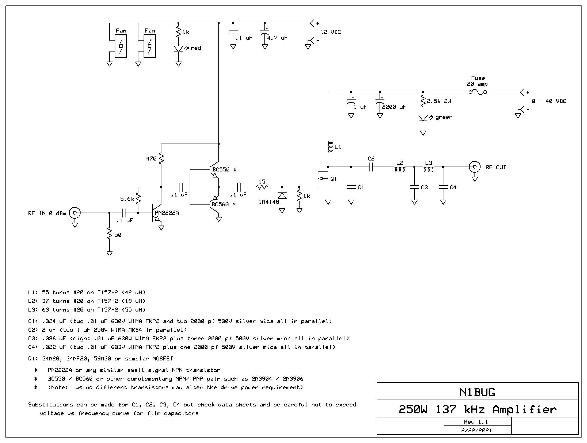
Use caution when selecting capacitors for the output circuit, namely C1 through C4. It may be very tempting to use a single capacitor of the specified value, but doing so will likely mean operating the capacitor beyond its voltage ratings if it is a film capacitor. Film capacitors must have their voltage derated as frequency increases. Capacitor data sheets usually have curves for this derating. I had capacitors in a 630 meter amplifier fail because I had not taken that into account. Generally smaller value capacitors can handle more voltage at a given frequency than higher value ones, which is why I use several low value capacitors in parallel to reach the desired capacitance.
When selecting a FET, choose something rated 200 volts or more if you plan to run this amplifier at full power. Voltage peaks at the FET drain are about 3.5 times the applied DC voltage. So with 40 VDC on it, the FET is going to see a peak voltage around 140 volts on every RF cycle.
The FET requires good heat sinking. I prefer either directly mounting the FET with a bit of thermal grease to a heat sink isolated from ground (note the heatsink will have drain voltage and RF on it, so be careful what might come into contact with it) or a mica insulator with thermal grease for a normal grounded heat sink. I do not recommend using greaseless Sil-pad thermal pads as they may be unable to provide adequate cooling efficiency. The heat sink on my amplifier is about 5 x 3 x 1.5 inches. A fan on the heatsink is not required for low duty cycle such as two minute WSPR transmissions at 33% or lower duty cycle. For long T/R period modes or frequent transmission resulting in high duty cycle, you will need either a larger heatsink or a fan. I also have a fan on the bottom pushing air into the amplifier and air exhaust vents on the other end. Again, this is not needed for short transmissions of low duty cycle but if you are going to run 15 or 30 minute modes or very frequent transmissions, it will be necessary to supply cooling air to L1 and L2. I also have an internal fan assuring high volume air flow across those inductors, though that is probably not needed. It was there to move air across the inductors before I added the bottom cover and intake fan, and I didn’t bother removing it.
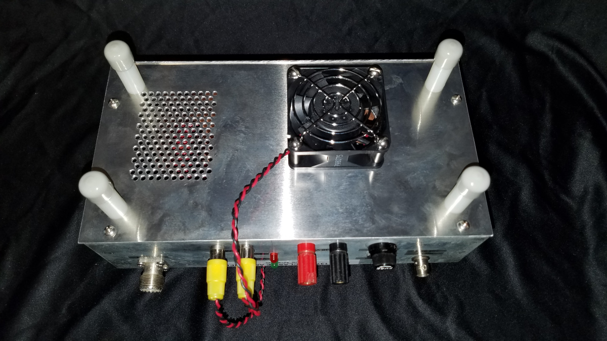
As noted in the previous post, this amplifier was constructed by making “islands” in a solid copper plated PC board using a Dremel rotary tool. Other methods will surely work as well.

The only future change I might make is to replace the little TO-220 size 34N20 FET with a FDA59N30 in the larger TO-3P package. I have not experienced any FET failures with the present configuration but I like the larger FETs for better cooling efficiency.
Pingback: A Low Drive 2200 Meter Amplifier | N1BUG Adventures in Radio