
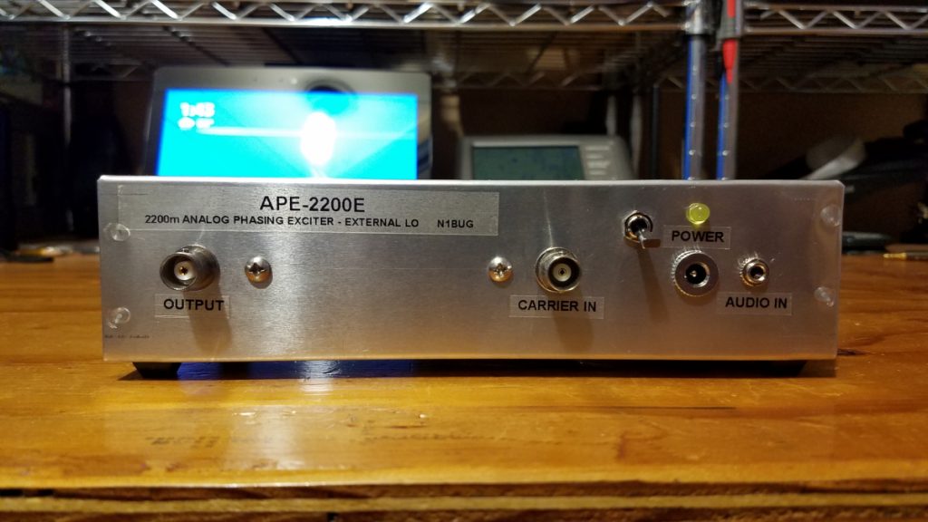
In early 2020 I began phasing out much of the first generation LF equipment and building replacements. My LF operating interests focus largely on DX. As I have learned more about all of this, it became obvious I needed some upgrades. This is the second in a series of posts about new equipment for our lowest frequency amateur radio allocation.
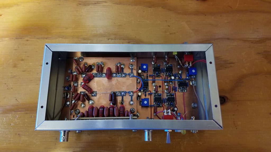
Like the first generation receiver, the transmitting downconverter did not have adequate frequency stability for slow modes on LF. I also wanted something that didn’t tie up my only HF rig when operating on 2200 meters. After reviewing several designs for phasing exciters I settled on a design by W1VD. I built mine Manhattan style using MEPads and MESquares from QRPme.
The MPS6650 and MPS6652 transistors used by W1VD are no longer available. I successfully substituted BC33716BU and BC32716BU devices but I have not been able to achieve the stated +20 dBm output. Mine will only make +16 dBm before the output waveform becomes distorted. This works OK with my amplifier but is a subject I would like to revisit at a later date.
Initially I encountered some difficulty getting good carrier and opposite sideband suppression. I traced the problem to the LO signal to the two mixers not being 90 degrees out of phase. I built several variants of the quadrature hybrid but I could not get accurate 90 degree phase shift or equal amplitude. Trying some alternate approaches, I achieved success using a Wilkinson divider and phase shift network. Some cut and try adjustment of two capacitor values was needed but in the end I achieved accurate 90 degree phase shift with similar amplitude on both ports. I used 6 dB resistive attenuators on the two LO signals before feeding the mixers. The two outputs from this circuit go directly to pin 8 on the two SBL-3 mixers in the exciter. The 6 dB pad, C1, C2, T1, C3, C4 and the associated 49.9 ohm resistor shown in the W1VD exciter schematic were omitted. With this arrangement I was able to achieve better than 55 dB carrier and opposite sideband rejection after careful adjustment of the level and phase balance trimmers in the exciter. If you build this and find it is operating on the wrong sideband, reverse the LO inputs to the mixers. If you look closely at the blue and orange wires coming off the LO divider and phase shift board, you will see they cross over each other on the way to the mixers on the main board below. Mine had ended up being on lower sideband the first time around! One other change should be made to the phasing exciter if you will be operating it into a 50 ohm load: omit the 49.9 ohm resistor in series with the output. The 1 uF capacitor should connect directly to the junction of the two 5.1 ohm resistors.
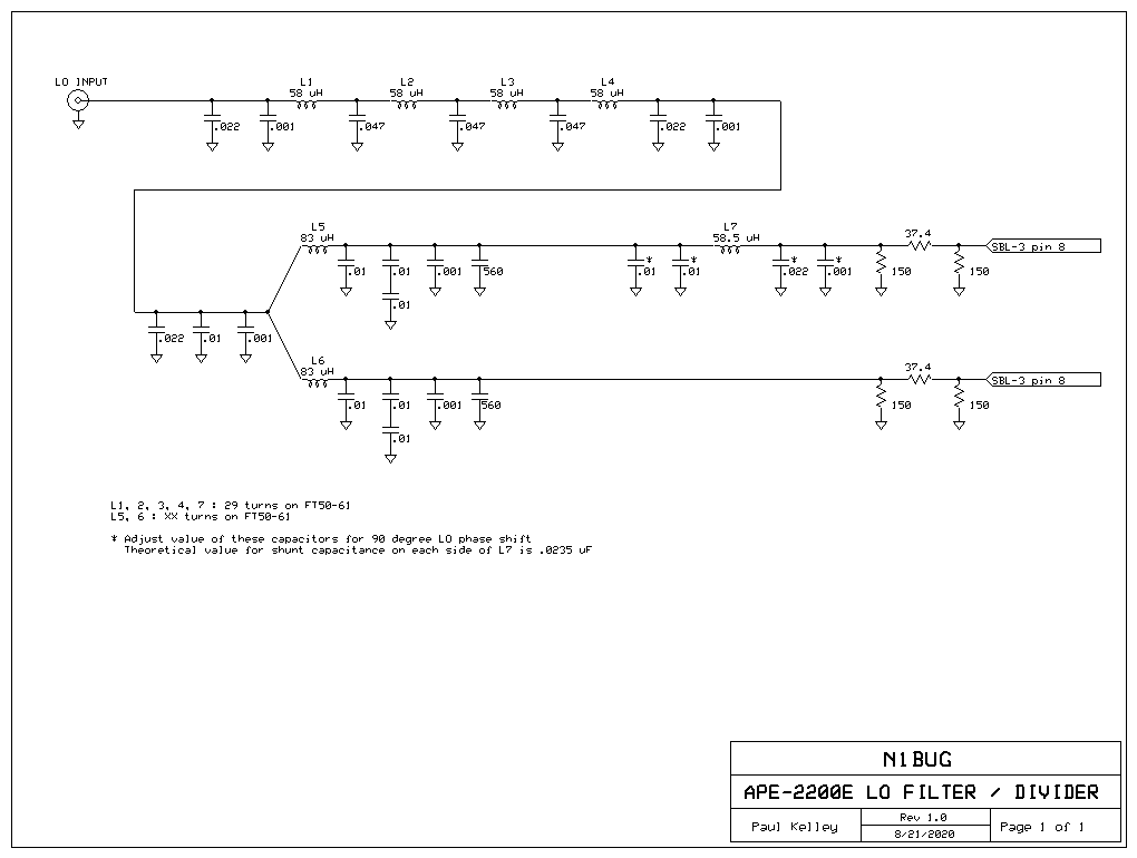
I am using the same Leo Bodnar GPS Clock that supplies 408000 Hz to the new receiver. It supplies 136000 Hz square wave to the exciter, which I low pass filter before the divider.
I have many hours of operation with this exciter in various modes. It has performed well. One thing this exciter does not like is magnetic fields which can couple 60 Hz energy to the audio circuits. Don’t put it too close to a linear power supply!