
In early 2020 I began phasing out much of the first generation LF equipment and building replacements. My LF operating interests focus largely on DX. As I have learned more about all of this, it became obvious I needed some upgrades. This is the first in a series of posts about new equipment for our lowest frequency amateur radio allocation.
After using the original modified SoftRock Lite II receiver for three years, it was time to move on. That first receiver served me very well. With it I was able to make three trans-Atlantic QSOs, and heard a lot of DX on various modes. In the end, however, I wasn’t satisfied with the frequency stability of the crystal oscillator, which was about 1 ppm, or a little less than 0.15 Hz drift on 2200 meters. That may seem completely insignificant to the HF, VHF or microwave operator but for the most serious DX pursuits on LF it not sufficient. With the one watt EIRP legal power limit, propagation and high noise levels at 137 kHz we need very slow modes to succeed over great distances. As a general concept, the slower the mode the greater the frequency stability needed. Legacy modes include QRSS (extremely slow CW meant to be read visually from a waterfall) and its derivatives like DFCW. Readers may recall my first DX QSO with 2E0ILY used DFCW60, meaning that each “dit” or “dah” takes 60 seconds to send! Drift of 0.15 Hz is clearly visible at that speed and can lead to difficulty “reading” signals at even slower speeds. Today we have various slow digital modes for beaconing and QSOs. At the extreme, EbNaut requires transmitter and receiver drift be no more than a few tens of microHertz! Others are more tolerant but current evolution suggests one should strive to stay within 0.01 Hz or better during any 30 minute period if DX is of prime interest.
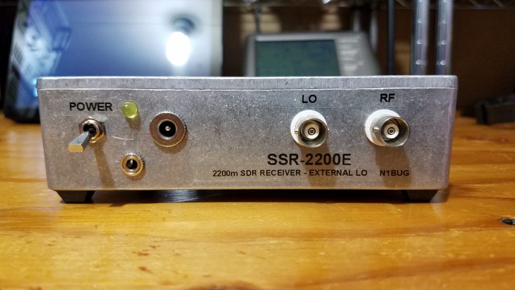
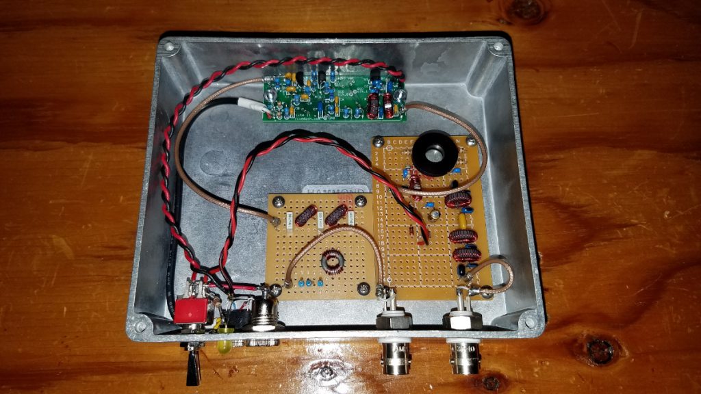
During those first three years I had tried various receiver, filter and preamp configurations. I now know what is needed with the SoftRock and my available antennas. I wanted to combine the filter, preamp and receiver into one box but I wanted to use a GPS referenced local oscillator for stability. In the end I settled on a design which puts all but the local oscillator into one box. The LO is a separate Leo Bodnar GPS Clock which supplies 408 kHz for the receiver (divided by four in the SoftRock quadrature LO generator) and 136 kHz for a 2200m phasing exciter.
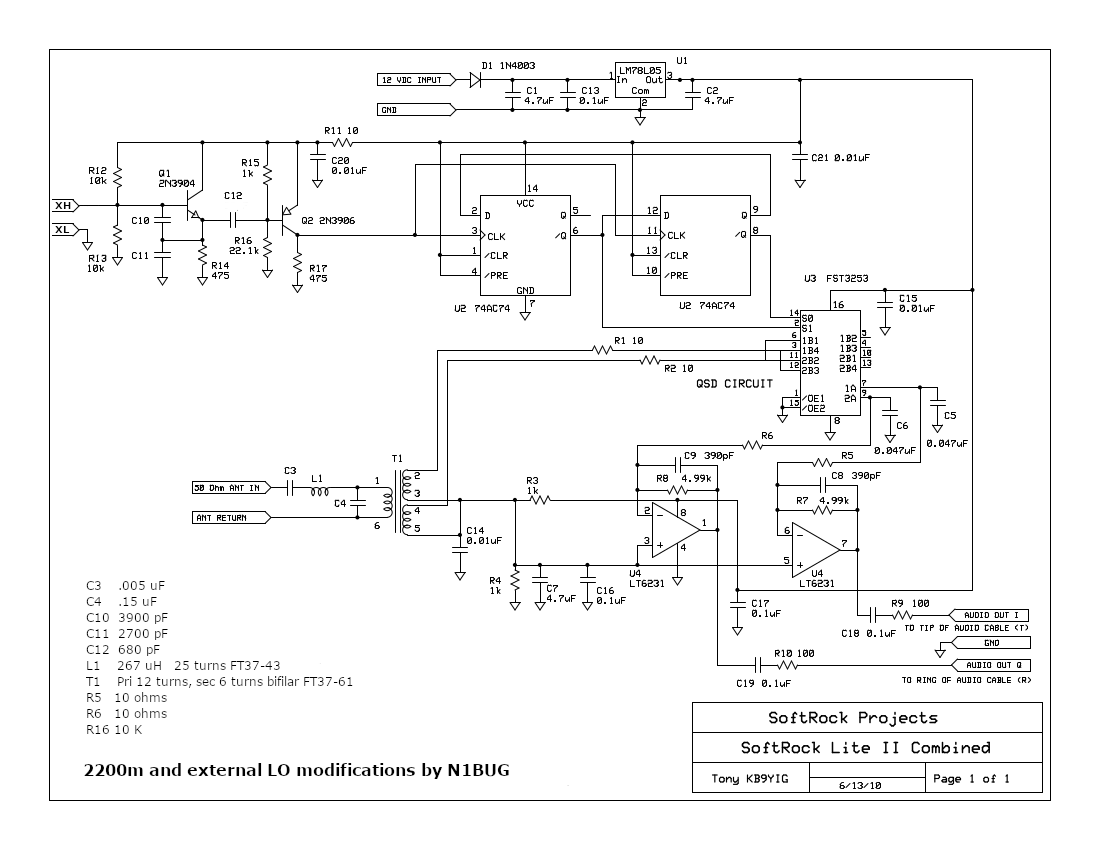
The major building block for the receiver is a SoftRock Lite II kit from Five Dash. A few modifications need to be made for 2200m operation. The schematic shows the values for parts that need to change for operation on this band (C3, C4, C10, C11, C12, L1, T1, R5, R6, R16), as well as the removal of the crystal and external LO connections in its former place. The capacitors can be ceramic. I recommend mounting the SoftRock Lite II board with the insulating hardware that comes with it. Ideally one wants everything isolated from the metal box except for the shield of the audio cable connector. To maintain that one ground point I run the receiver either on a battery or an isolated wall wart.
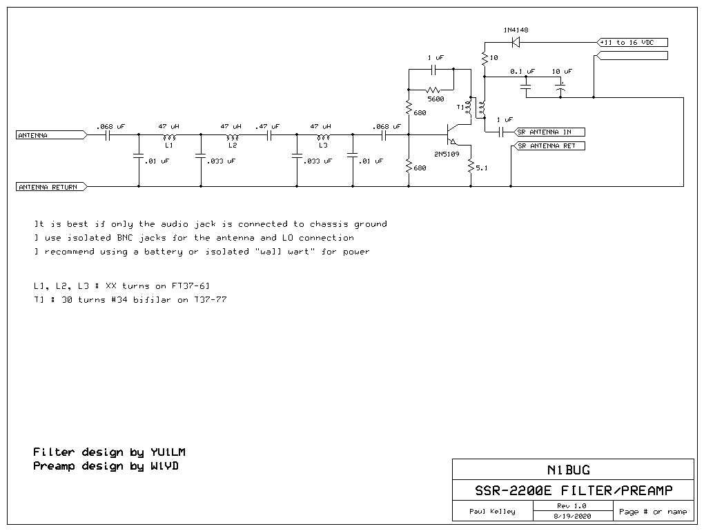
For the front end stages I have married a filter design by YU1LM and a preamp design by W1VD. The filter provides a bandpass response to keep out of band signals from overwhelming the receiver, while the preamp provides about 20 dB gain which is needed with many small receiving antennas on LF. You want enough gain in the front end and receiver so that the noise floor comes up at least 10 dB when you connect the antenna. If this seems a little different from conventional advice, consider that we are dealing with extremely weak signals where even fractions of a dB can make a difference. If we want to keep the signal to noise ratio from being degraded a meaningful amount, we need that much gain to be sure the SoftRock and sound card noise floor don’t degrade S/N of the system. With the exception of the 10 uF electrolytic, all capacitors are ceramic types.
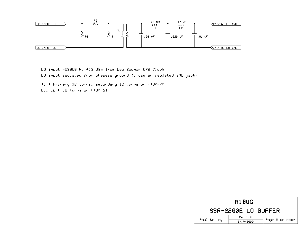
Next I needed a suitably stable local oscillator. We need a final LO frequency that is close enough to the 2200 meter band to allow tuning it with whatever sound card will be used. If the sound card sample rate is 96 kHz, we need to be within 48 kHz of the receiving frequency. I recommend staying a few kHz less than that due to the way anti-aliasing filters in sound cards work. This means we want our LO to be between about 96 kHz and 178 kHz in practice, preferably avoiding putting it “in band”. The LO frequency is divided by four in the SoftRock quadrature generator circuit. This means we need to inject a frequency four times higher into the receiver. Anything between 384 and 712 kHz will work. I was already using one of the two outputs from the GPS Clock to provide 136000 Hz LO to my phasing exciter. Available frequencies for the second output are somewhat limited and tied to the first frequency but in this case 408000 Hz is one of the options, and it is perfect. That puts our final LO at 102 kHz, comfortably within range, yet far enough removed from the band of interest to put the image frequency around 67 kHz, well down the slope of the receiver front end bandpass filter. Perfect!
First I tried injecting the 408 kHz square wave directly into the SoftRock. It worked but I didn’t have a good feeling about it. For one thing, that meant that the SoftRock and GPS clock grounds were connected, a situation which I was trying to avoid in case of ground loops and noise getting into the system. The GPS Clock also didn’t like the impedance, causing it to put out not only the harmonic rich square wave but also a significant amount of HF energy as ringing due to impedance mismatch. I tried using a transformer (for ground isolation) and low pass filter to clean up harmonics but this made the GPS Clock even less happy with a lot of ringing due to reflections. Since I had signal to spare I solved this, albeit somewhat crudely, but inserting a 10 dB attenuator between the GPS Clock and transformer. This gave a nice clean sine wave at sufficient level into the SoftRock LO circuit. I don’t claim this design to be elegant or perfect, but I do claim it works well for me. I used film capacitors in the filter because I had them on hand, but ceramic should be quite acceptable.
This new receiver has been in operation for several months. Sensitivity and gain is more than adequate for use with my LNV antenna. Frequency stability is now determined almost entirely by sound card sample rate drift and is on the order of 0.01 Hz over several hours. This is sufficient for all but EbNaut, where the sound card sample rate requires continuous monitoring and correction. I have not conquered that yet.
Pingback: 2200m Reboot: Phasing Exciter | N1BUG Adventures in Radio