
On the morning of January 15 I was nearing the end of a 72 hour test of the JT9 submodes (JT9-10, JT9-5, JT9-2, JT9-1) on 136.395 kHz. The transmitter had been running 87% duty cycle for two days and as far as I knew all had been well. On this morning I checked in on things when I got up just before sunrise. It was running as expected with the waveforms on the ScopeMatch looking normal. I went about some morning chores and came back about 20 minutes later to check again. The transmitter was still running but the antenna was far off resonance. Minor changes are common but this was more than a minor change. I knew something was very wrong.
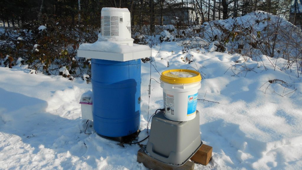
I quickly shut down the transmitter, grabbed my binoculars and went to the window to inspect the antenna. All wires were up and intact. I then hastily bundled up and went outside to check the loading coil / variometer. It didn’t take long to realize where the trouble was. When I removed the cover from the assembly housing, acrid smoke came billowing out and I could feel heat radiating from somewhere inside. This was not good! Since the smoke was so thick and presumably toxic, I could not do a full inspection until things had aired out a while.
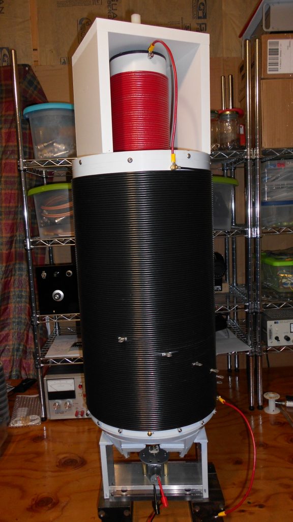
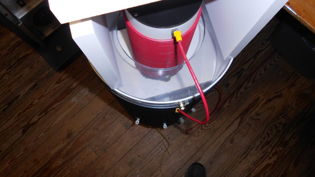
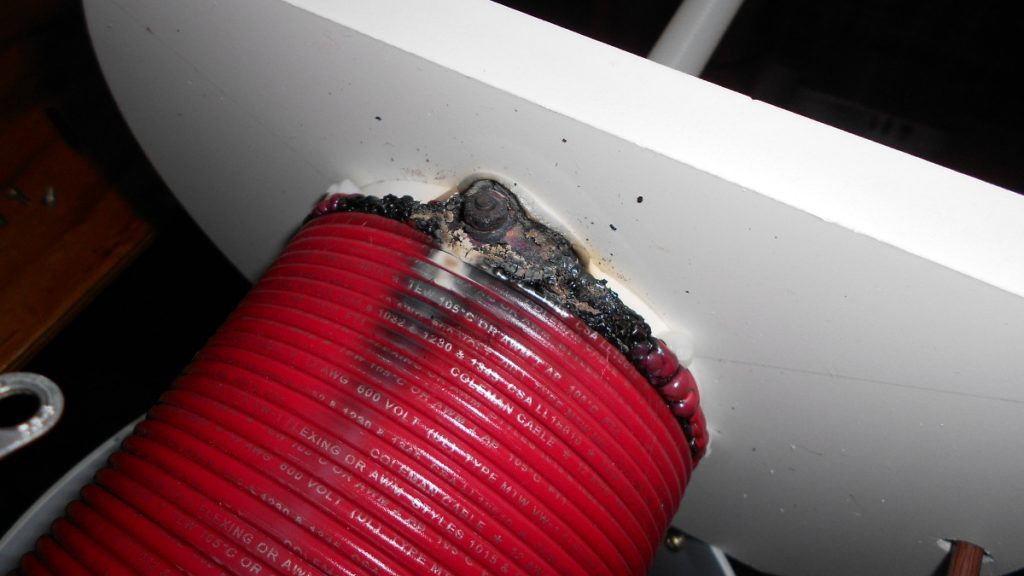
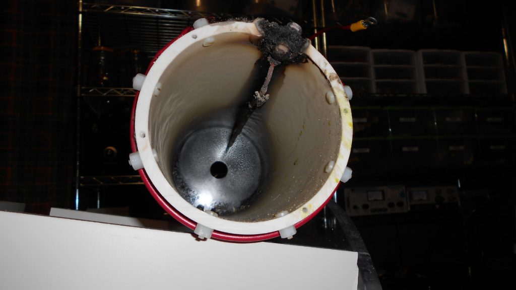
Upon subsequent inspection I found the bottom of the moving inner coil badly damaged. I can only guess as to what happened. Careful inspection of the following pictures will reveal something of the construction. There was a wire (12 AWG solid, insulated) running down the length of the form on the inside. This provides connection from the bottom of the inner coil to a a terminal at the top of the coil form which is jumpered to the top of the large outer coil. At both ends, the method of feeding through the form was a 18-8 stainless machine screw with washers and nuts as needed. On the inside the ring lug on the wire was between the head of the machine screw and the coil form. Stainless hardware may not have been an optimal choice. It stays clean practically forever but it has poor electrical properties. I had assumed it would be fine with the expected 2 amps or so of low frequency RF current.
What I suspect happened is that over time, probably aided by thermal expansion and contraction cycles of the PVC form, the hardware became loose on that bottom connection. As it began to loosen slightly, resistance of the connections may have increased somewhat, leading to more heat being generated. This may in turn have led to some slight softening of the PVC, allowing pressure on the connections to relax even more. I believe eventually it became so loose there was arcing which produced extreme heat in a localized area, eventually leading to the damage.
In hindsight, there may have been two warning signs that something was not right. If these were signs of failure in progress, things had been going south for some time. About two or three weeks prior to this incident I had noticed that when I was transmitting I would sometimes see “fuzz” appearing on both sides of my signal when viewed on the waterfall of my SDR receiver. It usually lasted only for several seconds, then cleared up. I did wonder about arcing, but the ScopeMatch looked perfectly normal. I put it down to just another artifact of severe receiver overload. It’s not as though my signal ever looked clean in the local receiver! There was always plenty of junk, no doubt worsened by the use of back to back diodes across the receiver front end to prevent damage from my own transmissions. But this particular “fuzz” phenomenon was something I hadn’t recalled seeing previously.
The second possible warning sign came 24 hours prior to discovery of the failure. On that morning resonance suddenly “jumped” higher in frequency. It wasn’t a big change, but was something I hadn’t seen before in benign weather conditions. Re-resonating took care of it but about an hour later it “jumped” back to the original resonance condition and needed to be adjusted again. This unexplained behavior should have been a warning that something was not right.
Much of what I think I know about this failure is speculation based on inspection after the fact. My theory seems further supported by the fact that the other stainless machine screws passing through this form had all loosened considerably. I know they were tight when it was built, but I was able to remove them using just my fingers. I will never know for sure exactly what happened, but the new inner coil will be designed to avoid the suspected failure scenario. If it fails again, I will have to reexamine my theories!