
Last year I acquired some transverters with the idea of getting back on the VHF and UHF bands. I only have one station transceiver so everything has to work from that. The transceiver’s ANT 1 connection normally goes to the input of my 160-10m amplifier, ANT 2 to the input of my 6m amplifier, and RX ANT IN to a low band receive antenna switching and control unit. For use with a transverter, I need ANT 1 to go to a transverter drive attenuator, the output of which goes to the transverter IF input (transmit), RX ANT IN to the transverter IF output (receive). This requires me to remember to change two switches, and forgetting one during a quick band change can be disastrous. I proved that last year when I forgot a switch and accidentally dumped 1500 watts of RF into the makeshift drive attenuator I was using at the time. Poof! Szzzt! There went the magic smoke, costing me $40 for another hybrid attenuator. The situation gets even more complicated when more than one transverter is involved and the correct one must be selected. Since I have several amplifiers sharing a common high voltage supply it is also important that the correct one (and only the correct one) be enabled for transmitting while all the others be locked into standby. This was a nightmare!
Clearly I needed a better system. What I needed was automation of the process. A band decoder connected to the transceiver band data socket would do no good since that would only support bands that are native to the radio – 160 through 6 meters. Since I always have CAT software running (DXLab Commander) while operating there was another option. I could add a parallel port to my PC and configure it so that Commander would make one of the data pins go high for HF, another for 6 meters, another for 2 meters and so on. I could then build a control unit and add relays to do all the band switching tasks.
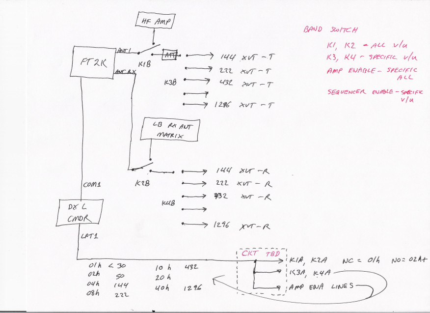
Concept drawing
The first thing I did was sketch a basic concept diagram so I could better visualize what I needed. I was going to need two regular SPDT coaxial relays; one to route the transceiver’s ANT 1 connection to either the input of the 160-10m amplifier (for HF) or to the transverter drive attenuator (for VHF/UHF), the other to route the transceiver’s RX ANT IN to the low band antenna switch box (for HF) or to one or more transverters (for VHF/UHF). To select the proper transverter I was either going to need a lot of relays in a complex matrix or I was going to need two single input, multiple output matrix relays ready made. I found two of the latter on eBay. Specifications were not available and I have no idea what they were made for, so I took some measurements. At 28 MHz, worst case port to port isolation is 90 dB. That’s good enough! Although I don’t fully trust the accuracy of my return loss measurement, it is at least in the ballpark. The relays measured 29 dB (1.07 VSWR), again plenty good enough). They obviously aren’t designed to handle much power but they don’t need to in this application. There will only be 10 milliwatts (+10 dBm) on the transmit relay.
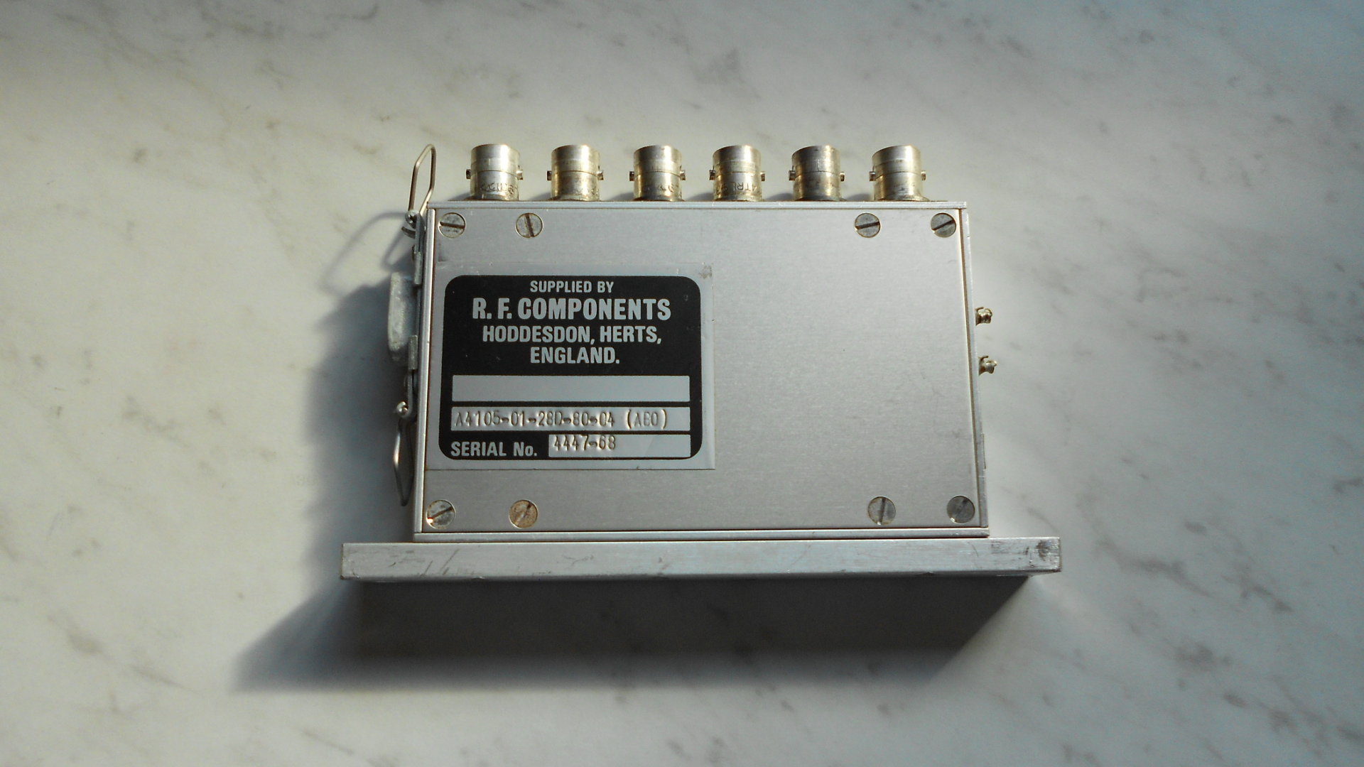
One of the two transverter IF switching relays
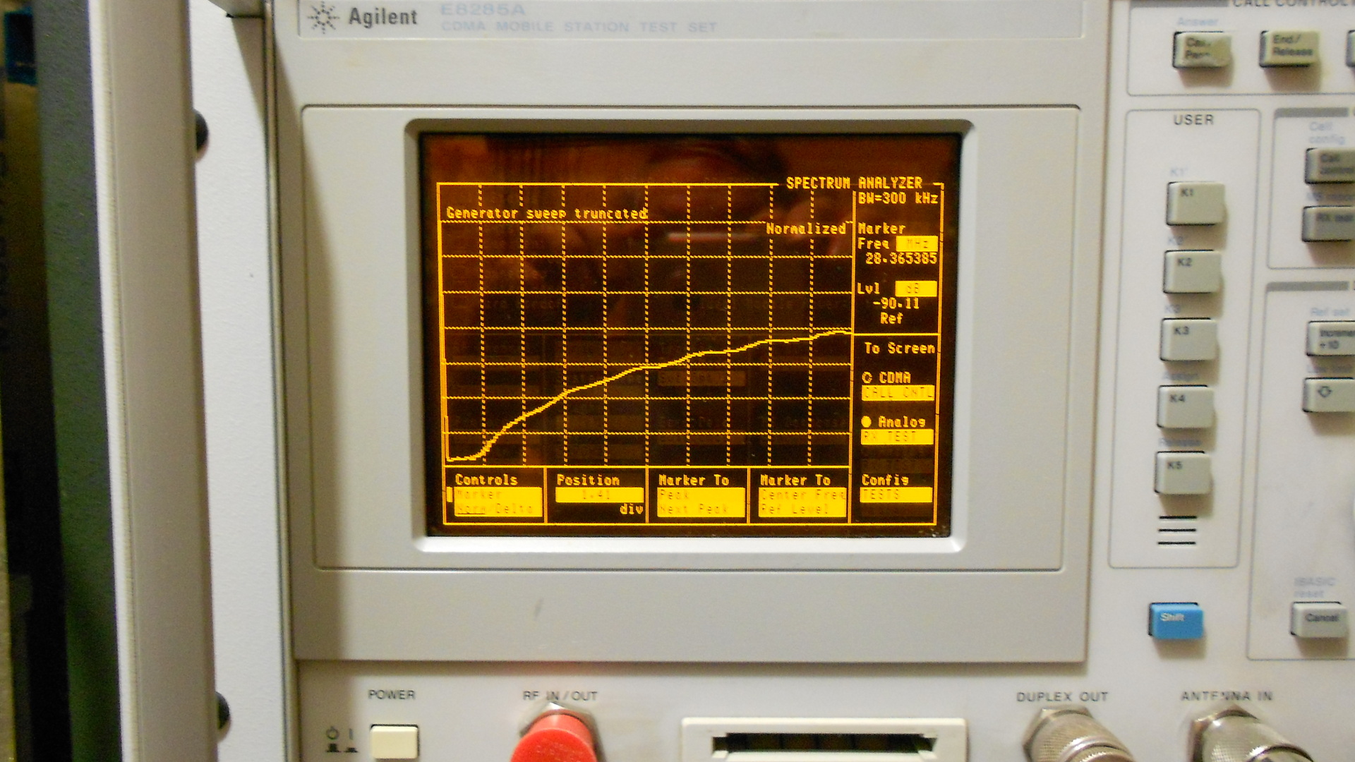
Relay isolation test
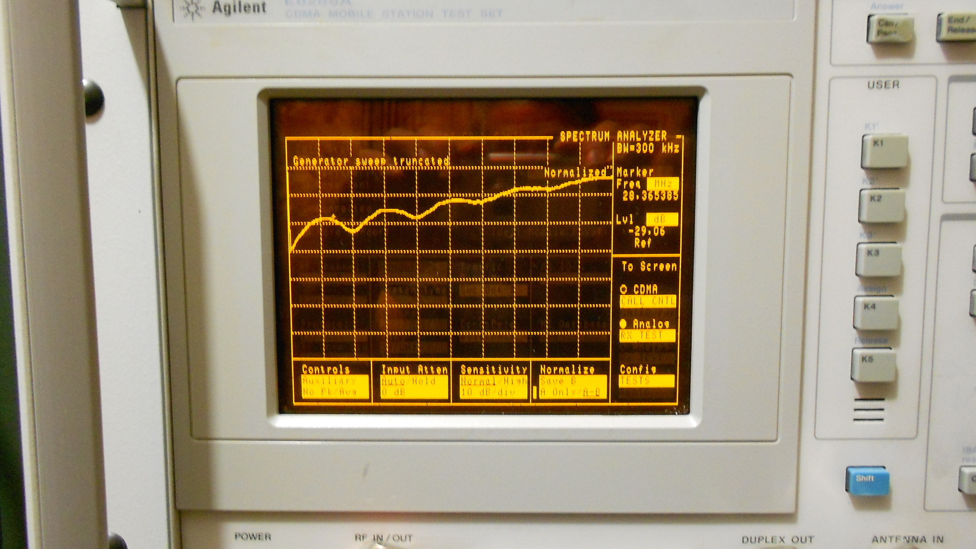
Relay return loss test
The next step was to start thinking about control circuit configuration. For HF and 6
meters, the only action to be performed would be to enable one
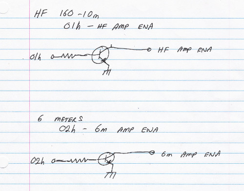
Concept for switching circuit, HF or 6m amp enable
of the amplifiers. Except for the enable relay which would be added to each amplifier, all other system relays would be de-energized for these bands, thus needed no switching. Out came the pen and paper for a little more design concept drawing. It would be elegant to use opto-isolators to interface the parallel port data lines from the relays to be switched, but that would involve buying a lot of parts. I wanted to use what I had, and I had drawers full of small transistors that could be used as switches in this application. I selected the venerable PN2222 transistor for this task. A look at the data sheet was promising but I wanted to verify that its actual DC current gain (hFE) was adequate for a good hard switching action in this application. The first thing I needed to know was how much current I could safely
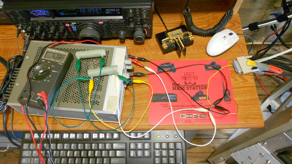
Testing PN2222 DC current gain ‘in circuit’
draw from the data lines on my PC’s newly added parallel port – a Rosewill RC-302E PCI-e adaptor. I measured open circuit voltage at 3.30 volts. With a 1k ohm resistor to ground that dropped to 3.18 volts at 3.2 milliamps of current. The minimal voltage drop indicated this should be safe enough and would not damage the RC-302E. Allowing for 0.6 volt drop across the PN2222 base-emitter junction, this would leave me with about 2.6 mA base current (3.18-0.6 equals 2.58 volts across the 1k resistor). Cobbling together a quick and dirty test circuit I found that at 250 mA through the collector-emitter circuit, voltage drop across the PN2222 was less than 0.6 volt. In reality I only need to draw about 40 mA with the relays I plan to use, so this was more than good enough.
To be continued…