Building a 630-Meter Transmit Converter

Inside view of completed 630m transmit converter

This is a companion to my earlier 2200-meter transmit converter. Refer to that post for more details. This one produces about 25 dBm output. Not much is different here except for component values in the low pass filter and the trimmer potentiometer. I didn’t have another of the same type and value. It isn’t critical since it is only being used as a voltage divider to set bias on the BS170 FET.


Schematic diagram and parts values for the 630m transmit converter

Building a 2200-Meter Transmit Converter

I recently began running a WSPR beacon on 2200 meters. Beaconing is fine, but I also want to be able to make QSOs on this new band. To that end I needed a very low cost transmit converter so that I could use my FT-2000, which is fully interfaced to the computer for digital modes. Dave, AA1A came to the rescue with an old Anzac MD-143 mixer. The rest I built from stock parts and the junk box. Stock parts are new, current production parts I keep on hand for projects. The junkbox is a collection of old, surplus, used, salvaged and anything else I happen to be able to get my hands on. I don’t need a linear converter or amplifier for this band, and the resulting converter is not linear. It can be used on CW and any mode which does not require linear amplification.

The converter post-mixer amplification and low pass filter are separate from the mixer

The MD-143 takes a nominal 7 dBm local oscillator signal in the 5 to 500 MHz range. For RF it likes about 0 dBm in the same range. Conversion loss is around 6 dB so we can expect about -6 dBm output at the IF port, which is rated DC to 500 MHz. I wanted to get that up to 24 dBm (250 milliwatts) so it provide the same amplifier drive level as my Ultimate 3S beacon transmitter. The fewer things I have to remember when switching modes, bands, activities or exciters the better! I knew I could use a BS170 FET and low pass filter to duplicate the amplifier section of the Ultimate 3S but I would need something on the order of 10 dBm drive to assure equal output. Wayde, K3MF, suggested using a venerable 2N3904 and kindly sent a long a copy of a schematic. This was good because I have a drawer full of 2N3904 transistors! Some quick and dirty breadboarding and testing showed that I could get 12 dBm out of it with -6 dBm input from the mixer. Perfect!

Inside view of the completed post-mixer amplifier and low pass filter

I set about throwing a circuit together. I was only going to be building the post-mixer amplification and low pass filter stages since I wanted to use the Anzac mixer with this and a similar unit for 630 meters. It’s really very simple: a 2N3904 which produces a nice square wave output followed by a BS170 and finally a low pass filter. There is a 5 volt regulator to power the BS170 in order to hold it to the 24 dBm output level, same as in the Ultimate 3S which runs on 5 volts. After throwing the thing together, it showed exactly 24 dBm output on the first try! Whoa… let me note this on my calendar. It’s a historic occasion!

I am temporarily using my trusty HP 3325B function generator as a 10 MHz local oscillator. When I can afford it I plan to get a dedicated 10 MHz LO for this converter, ore more appropriately one that can be shared between this and its soon-to-be-built 630 meter counterpart. My FT-2000 has been modified for general coverage transmit so I can use it on both bands (10.135.7 to 10.137.8 for 2200 meters and 10.472 to 10.479 for 630 meters.

There is not much else to say about this. I am including a schematic for those who may wish to borrow ideas from this simple gadget. Unfortunately I am reduced to posting photographs of schematics since my printer/scanner finally died after many years of faithful service.

Schematic diagram of the post-mixer amp and LPF stages of the converter


Finally QRV on 2200 Meters!

Results of my second night of WSPR transmissions. W3PM is 1909km from me.

I have been so busy with station building projects that I have failed to write about several of them. Those have resulted in my station being able to transmit on the 2200 meter band after nearly ten months of work toward that goal. In my first two nights running a WSPR beacon at 12 watts transmitter power I have been heard by more than a dozen stations at distances to 1909km (1186 miles). My effective isotropic radiated power (EIRP) is less than 0.1 watt, which is 10 dB down from the legal limit. I am confident my station can span the Atlantic on this band when I reach full legal limit.

My sincere thanks to NI7J/WH2XND for help getting QRV, also to K7PO/WH2XXP for help with an upcoming project to increase transmitter power.

My transmitting antenna is a Marconi in a T configuration with 27m vertical and a top hat consisting of three 30m parallel wires spaced 1.5m apart.

This is the loading coil / variometer for the antenna. Maximum inductance of this coil is 2500 uH. My antenna requires about 2250 uH to resonate at 137.5 kHz. I’m still thinking about a proper replacement for the spring clip.

Low Noise Vertical for LF and MF Receiving

The LNV antenna with my southwest tower (which is the transmitting vertical for 160 meters) behind it

Note 12 May 2018: I moved this antenna to a new location and made a discovery. It had been working in part due to mutual coupling with my transmitting antenna. I should have known this because when I resonated the transmitting antenna on 2200m the LNV noise floor and signal levels came up about 20 dB on that band. Similarly when I resonated the transmitting antenna on 630 meters, output of the LNV came up nearly 10 dB on that band. When I moved it away from the transmitting antenna, output on both bands dropped to within 3 dB of my receiver noise floor even with the preamp (my simple SDRs are not ultra sensitive). Another factor may have been that the new location was surrounded by trees. The antenna has been moved back to its original location. Subsequently, a new receiver allows noise from the LNV to be about 12 dB above the receiver noise floor.

During the initial phase of experimentation I had found that some of my 160 meter Beverage antennas worked reasonably well for receiving on 2200 and 630 meters. I was hearing plenty of Europeans on both bands. Obviously at these frequencies they didn’t work as Beverages. What the actual operating mode was I don’t know. There were a few problems with this arrangement, primarily that I couldn’t run LF and MF receive operations concurrently with 160 (or 80) meter DXing. That was not good!

After reading a number of blog posts and web articles about the “low noise vertical” or LNV, I decided to give it a try. VE7SL has an article on his blog with links to additional information. As is often the case I pulled ideas from several sources, then mixed and matched (and even went off on my own a bit) for my version. My LNV is a 30 foot self supporting vertical made from scrap aluminum tubing I had on hand. It starts out with 1.5 inch OD at the base and tapers to 1/2 inch at the top. The bottom foot of the vertical is slid inside a two foot piece of 1.5 inch schedule 40 PVC pipe and secured in place with set screws (bottom) and a worm clamp (top). Looking at the photo that may be confusing. The set screws (three 1/4-20 stainless tap bolts)  go through the worm clamp and PVC just above the transformer box. You can see that in the photo. What is not visible is the other worm clamp securing the aluminum tubing to the top of the short PVC section. These details are unimportant. Just make sure your vertical is insulated at the base! A piece of wire hanging from a tree would no doubt work just as well, but I wanted to do mine this way.

The base of the LNV antenna with transformer inside the plastic mini box

A couple of words about the overview photo at the top of this post. First, in the thumbnail you may not be able to make out the LNV in the foreground just to the right of the tower behind it. Second, usually the yagi antennas on that tower are lined up with each other! We had a recent storm with wind gusts to 70 mph which skewed things and I haven’t been up to fix it yet. The LNV is only 40 feet from that tower which is my 160 meter transmitting vertical (shunt fed). Thanks to good band pass filters, my 2200 and 630 meter receivers don’t react at all when I transmit with 1500 watts on 160.

In some write ups about the LNV it is said one needs more than one ground rod for best performance. Surprisingly I am using just one four foot “ground rod” which is a section of a stainless steel mobile antenna whip which I pushed into the sandy soil by hand! I plan to try adding real ground rods later but the antenna is working with the minimal ground. As of this writing it has heard 2E0ILY nine consecutive nights on 2200 meters.

LNV base transformer primary winding

My LNV is fed with about 250 feet of WD1A twisted pair wire which is laying on the ground. This is ex military field phone wire and is practically indestructible as long as you keep water out of the ends. It has three steel and four tinned copper strands in each conductor along with incredibly tough insulation that takes a lot of abuse. Any twisted pair wire should work fine in this application.

LNV base transformer secondary

The transformer at the antenna base is wound on a FT-114-JC core, 80 turns primary, 8 turns secondary. First, the 80 turn primary is wound directly on the core using 20 AWG enameled wire. If a non-coated core is used, it would probably be wise to wrap the core with some kind of tape before winding the primary. One end of the primary winding connects to the base of the LNV, the other end to the ground rod.

The primary was wrapped with teflon thread seal tape, then the secondary was wound over the cold (ground) end of the primary using 20 AWG solid plastic coated wire. Another layer of teflon tape keeps everything nice and tight. The secondary winding connects to the twisted pair feed line.

LNV base transformer in its protective box

The finished transformer is mounted in a small plastic mini box of the type that has a rubber gasket to keep out water. The ground and antenna connections are #8-32 stainless machine screws at opposite ends of the box, while the connections for the twisted pair feed line are together on one side of the box.

Twisted pair to coax transformer for the shack end of the feed line. The RCA connector has subsequently been replaced by a BNC

At the shack end of the feed line I use another FT-114-JC core with 8 turn primary (twisted pair from the antenna), 6 turn secondary for 50 ohm coax to the receiver (or in my case two receivers via a splitter).

After using this antenna for 10 days, initial results are very promising, especially on the lower band. I am not able to listen with this and the old antenna at the same time, but I am hearing 2E0ILY on 2200 meters much more often and with stronger signals than I ever did with the short Beverage. To the west it seems about on par with the Beverage. On 630 meters I don’t think it is quite as good, but I am hearing a number of Europeans.

Diagram of the LNV antenna

Automating HF/VHF/UHF Band Switching – Part 1

Last  year I acquired some transverters with the idea of getting back on the VHF and UHF bands. I only have one station transceiver so everything has to work from that. The transceiver’s ANT 1 connection normally goes to the input of my 160-10m amplifier, ANT 2 to the input of my 6m amplifier, and RX ANT IN to a low band receive antenna switching and control unit. For use with a transverter, I need ANT 1 to go to a transverter drive attenuator, the output of which goes to the transverter IF input (transmit), RX ANT IN to the transverter IF output (receive). This requires me to remember to change two switches, and forgetting one during a quick band change can be disastrous. I proved that last year when I forgot a switch and accidentally dumped 1500 watts of RF into the makeshift drive attenuator I was using at the time. Poof! Szzzt! There went the magic smoke, costing me $40 for another hybrid attenuator. The situation gets even more complicated when more than one transverter is involved and the correct one must be selected. Since I have several amplifiers sharing a common high voltage supply it is also important that the correct one (and only the correct one) be enabled for transmitting while all the others be locked into standby. This was a nightmare!

Clearly I needed a better system. What I needed was automation of the process. A band decoder connected to the transceiver band data socket would do no good since that would only support bands that are native to the radio – 160 through 6 meters. Since I always have CAT software running (DXLab Commander) while operating there was another option. I could add a parallel port to my PC and configure it so that Commander would make one of the data pins go high for HF, another for 6 meters, another for 2 meters and so on. I could then build a control unit and add relays to do all the band switching tasks.

Concept drawing

The first thing I did was sketch a basic concept diagram so I could better visualize what I needed. I was going to need two regular SPDT coaxial relays; one to route the transceiver’s ANT 1 connection to either the input of the 160-10m amplifier (for HF) or to the transverter drive attenuator (for VHF/UHF), the other to route the transceiver’s RX ANT IN to the low band antenna switch box (for HF) or to one or more transverters (for VHF/UHF). To select the proper transverter I was either going to need a lot of relays in a complex matrix or I was going to need two single input, multiple output matrix relays ready made. I found two of the latter on eBay. Specifications were not available and I have no idea what they were made for, so I took some measurements. At 28 MHz, worst case port to port isolation is 90 dB. That’s good enough! Although I don’t fully trust the accuracy of my return loss measurement, it is at least in the ballpark. The relays measured 29 dB (1.07 VSWR), again plenty good enough). They obviously aren’t designed to handle much power but they don’t need to in this application. There will only be 10 milliwatts (+10 dBm) on the transmit relay.

One of the two transverter IF switching relays

Relay isolation test

Relay return loss test

The next step was to start thinking about control circuit configuration. For HF and 6

meters, the only action to be performed would be to enable one

Concept for switching circuit, HF or 6m amp enable

of the amplifiers. Except for the enable relay which would be added to each amplifier, all other system relays would be de-energized for these bands, thus needed no switching. Out came the pen and paper for a little more design concept drawing. It would be elegant to use opto-isolators to interface the parallel port data lines from the relays to be switched, but that would involve buying a lot of parts. I wanted to use what I had, and I had drawers full of small transistors that could be used as switches in this application. I selected the venerable PN2222 transistor for this task. A look at the data sheet was promising but I wanted to verify that its actual DC current gain (hFE) was adequate for a good hard switching action in this application. The first thing I needed to know was how much current I could safely

Testing PN2222 DC current gain ‘in circuit’

draw from the data lines on my PC’s newly added parallel port – a Rosewill RC-302E PCI-e adaptor. I measured open circuit voltage at 3.30 volts. With a 1k ohm resistor to ground that dropped to 3.18 volts at 3.2 milliamps of current. The minimal voltage drop indicated this should be safe enough and would not damage the RC-302E. Allowing for 0.6 volt drop across the PN2222 base-emitter junction, this would leave me with about 2.6 mA base current (3.18-0.6 equals 2.58 volts across the 1k resistor). Cobbling together a quick and dirty test circuit I found that at 250 mA through the collector-emitter circuit, voltage drop across the PN2222 was less than 0.6 volt. In reality I only need to draw about 40 mA with the relays I plan to use, so this was more than good enough.

To be continued…

Update on 2200 Meter Trans-Atlantic Reception

On the better nights I continue to receive WSPR2 signals from across the Atlantic on 137 kHz. Like my early EME days decades ago, the thrill remains high. I get excited beyond reason every time I see one of these pop up in my list of decodes. When I can predict which periods a station will be transmitting, I find myself intently watching the waterfall during those periods to see if I can visually detect anything. There are a large number of periods when the signal can be seen but does not decode. Factors that can prevent a decode on an otherwise OK signal include fading, atmospheric static (which is becoming ever more a factor as Spring approaches), and local interference.

I am convinced that much more frequent Atlantic crossings are possible. There are many nights when no capable stations are transmitting during the peak hours (or at any hour).

Below is an updated list of all 2200 Meter trans-Atlantic decodes to date.

2017-01-29 01:20 DC0DX    0.137469 -27 JO31lk 0.2  N1BUG FN55mf 5399
2017-01-29 02:18 DC0DX    0.137469 -24 JO31lk 0.2  N1BUG FN55mf 5399
2017-01-29 04:14 DC0DX    0.137469 -27 JO31lk 0.2  N1BUG FN55mf 5399
2017-01-29 07:08 DC0DX    0.137468 -27 JO31lk 0.2  N1BUG FN55mf 5399

2017-01-30 06:12 DC0DX    0.137468 -25 JO31lk 0.2  N1BUG FN55mf 5399

2017-01-31 07:20 G8HUH    0.137425 -28 IO81mg 0.1  N1BUG FN55mf 4766

2017-02-01 07:10 DC0DX    0.137469 -27 JO31lk 0.2  N1BUG FN55mf 5399

2017-02-02 05:36 DC0DX    0.137469 -23 JO31lk 0.2  N1BUG FN55mf 5399
2017-02-02 05:58 DC0DX    0.137469 -24 JO31lk 0.2  N1BUG FN55mf 5399
2017-02-02 06:20 DC0DX    0.137469 -25 JO31lk 0.2  N1BUG FN55mf 5399

2017-02-06 04:26 DC0DX    0.137470 -24 JO31lk 0.2  N1BUG FN55mf 5399
2017-02-06 04:48 DC0DX    0.137470 -25 JO31lk 0.2  N1BUG FN55mf 5399
2017-02-06 05:54 DC0DX    0.137469 -26 JO31lk 0.2  N1BUG FN55mf 5399

2017-02-07 02:36 DC0DX    0.137470 -27 JO31lk 0.2  N1BUG FN55mf 5399

2017-02-14 22:32 2E0ILY   0.137551 -29 IO82qv 0.1  N1BUG FN55mf 4731
2017-02-14 23:28 2E0ILY   0.137551 -29 IO82qv 0.1  N1BUG FN55mf 4731
2017-02-15 04:40 G8HUH    0.137422 -24 IO81mg 0.1  N1BUG FN55mf 4766

2017-02-22 04:20 G8HUH    0.137424 -28 IO81mg 0.1  N1BUG FN55mf 4766
2017-02-22 04:30 G8HUH    0.137424 -25 IO81mg 0.1  N1BUG FN55mf 4766
2017-02-22 05:50 G8HUH    0.137424 -28 IO81mg 0.1  N1BUG FN55mf 4766

2017-02-23 05:06 G8HUH    0.137424 -26 IO81mg 0.1  N1BUG FN55mf 4766
2017-02-23 05:10 G8HUH    0.137424 -25 IO81mg 0.1  N1BUG FN55mf 4766
2017-02-23 05:14 G8HUH    0.137424 -24 IO81mg 0.1  N1BUG FN55mf 4766
2017-02-23 05:18 G8HUH    0.137424 -26 IO81mg 0.1  N1BUG FN55mf 4766
2017-02-23 05:22 G8HUH    0.137424 -27 IO81mg 0.1  N1BUG FN55mf 4766

2017-02-23 23:08 2E0ILY   0.137552 -29 IO82qv 0.02 N1BUG FN55mf 4731
2017-02-23 23:56 2E0ILY   0.137552 -27 IO82qv 0.02 N1BUG FN55mf 4731

2017-02-26 00:06 2E0ILY   0.137551 -28 IO82qv 0.02 N1BUG FN55mf 4731
2017-02-26 00:44 2E0ILY   0.137551 -28 IO82qv 0.02 N1BUG FN55mf 4731
2017-02-26 00:54 2E0ILY   0.137552 -28 IO82qv 0.02 N1BUG FN55mf 4731
2017-02-26 00:56 2E0ILY   0.137552 -28 IO82qv 0.02 N1BUG FN55mf 4731

2017-02-26 23:30 2E0ILY   0.137549 -28 IO82qv 0.02 N1BUG FN55mf 4731

2017-03-05 05:08 2E0ILY   0.137550 -28 IO82qv 0.2  N1BUG FN55mf 4731

2017-03-13 23:54 2E0ILY   0.137550 -27 IO82qv 0.2  N1BUG FN55mf 4731
2017-03-14 00:12 2E0ILY   0.137550 -27 IO82qv 0.2  N1BUG FN55mf 4731
2017-03-14 02:16 2E0ILY   0.137550 -28 IO82qv 0.2  N1BUG FN55mf 4731

2017-03-15 00:32 2E0ILY   0.137550 -28 IO82qv 0.2  N1BUG FN55mf 4731
2017-03-15 02:48 2E0ILY   0.137550 -29 IO82qv 0.2  N1BUG FN55mf 4731
2017-03-15 03:00 2E0ILY   0.137550 -27 IO82qv 0.2  N1BUG FN55mf 4731
2017-03-15 03:32 2E0ILY   0.137550 -27 IO82qv 0.2  N1BUG FN55mf 4731
2017-03-15 03:48 2E0ILY   0.137550 -25 IO82qv 0.2  N1BUG FN55mf 4731
2017-03-15 04:16 2E0ILY   0.137550 -27 IO82qv 0.2  N1BUG FN55mf 4731
2017-03-15 04:32 2E0ILY   0.137550 -27 IO82qv 0.2  N1BUG FN55mf 4731

Transverter Drive Attenuator

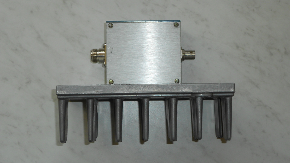
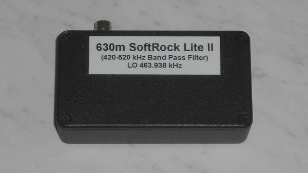
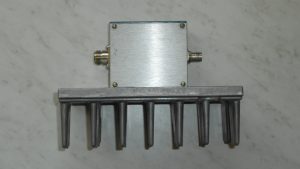
The completed attenuator and heat sink assembly

Edit: After writing this I devised a safe method to run the FT-2000 at 10 watts when on VHF/UHF. The entire band switching system is software-centric, controlled by DXLab Commander. Since the Yaesu CAT command set includes a method for setting power, I programmed each VHF/UHF band button to set the transceiver to 10 watts output. This is safe since there is no way to “bypass” software control in band switching where VHF/UHF is involved. The only possible glitch is in forgetting to reset power when going to HF, but this simply results in low power operation with no risk of equipment damage. In order to facilitate easy power resetting when going to HF I created an additional “HF” band button in Commander which disables the VHF/UHF system and resets power to 100 watts.

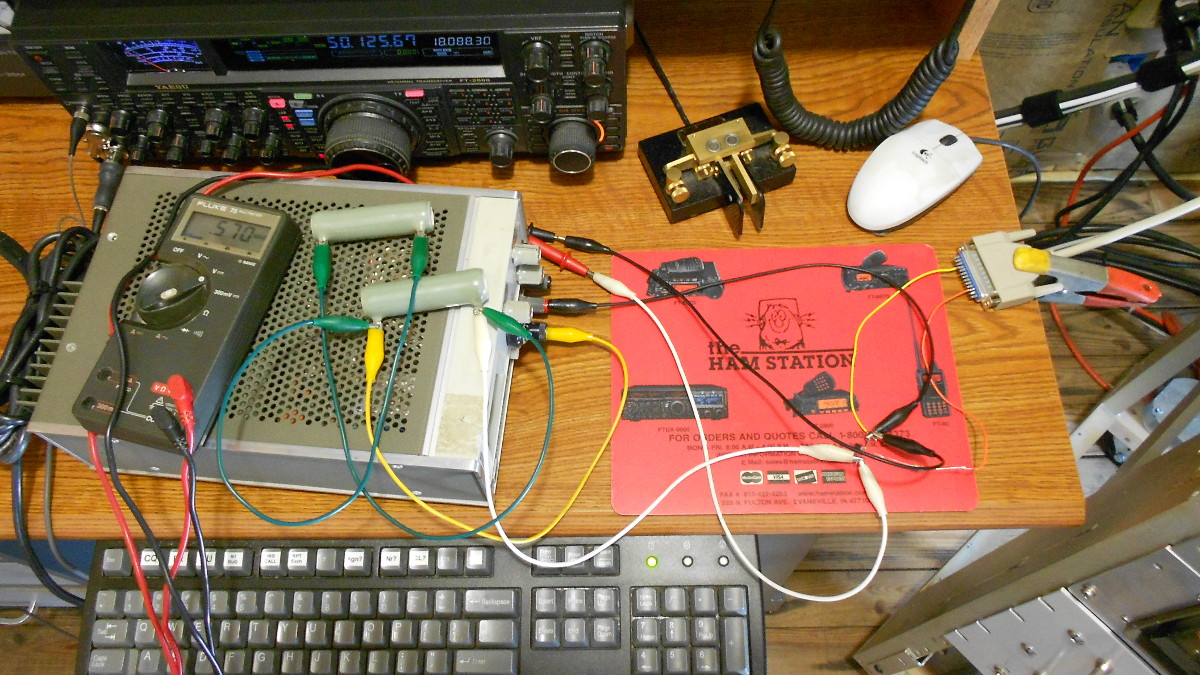
I needed an attenuator for driving VHF/UHF transverters. The goal was to take 100 watts of drive at 26 to 30 MHz down to +10 dBm (10 milliwatts) using whatever junk I could find. My 2 meter transverter uses a 26 MHz IF for 144 MHz, while my other transverters (222, 432, 1296 MHz) use a 28 MHz IF.

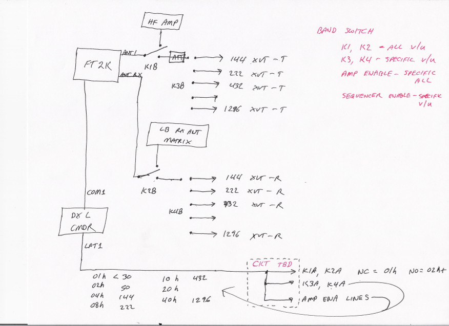
First, a few words about why. My Yaesu FT-2000 transceiver does have a low level transverter output. The level is -10 dBm, 20 dB below what I need. It could easily be amplified to reach the correct level, so why would I choose not to use it? The answer is both simple and complicated. I have just the one transceiver which I use from 1.8 to 144 MHz and hope to use for higher bands soon. Band switching all the stuff that needs to change going from HF to VHF or UHF with a transverter gets complex enough that I tend to forget things. I wanted to automate all the band switching tasks (RF routing to correct path, be it an HF amplifier or VHF transverter, enabling the correct amplifier while disabling all others, etc. I can easily do this using DXLab, which is my preferred multi function DXing software suite. DXlab understands transverters, so I can set it up to recognize what band I am on, be it 144, 222, 432 or even 1296 MHz, though the transceiver would be on 28 MHz for all of these. This would greatly simplify logging since the correct frequency would always be auto-filled in the logging software. The one stipulation in order to do all this is that band switching must be done through DXLab Commander in order for it to understand what band I am currently on when using transverters. If I set the band from the radio, Commander has no way of knowing that 28 MHz doesn’t mean I am operating on 10 meters!

Here’s the catch. On the FT-2000, the only way to activate the low level transverter output port is to switch to a special band called ‘AU’. This band is 28 MHz, but behavior is different from 10 meters in that on AU band the PA is disabled and the transverter output enabled. There is no way to do that when the radio is set to the normal 10 meter band or when sending a band/frequency request via CAT command. There is no CAT command for this AU band! It must be selected from the front of the radio, and not by a particularly intuitive process like all the other bands. If I used the transverter output, all my automation for band switching ideas would be out the window. Furthermore there would be confusion as to what band I was operating and I would have to manually edit frequency for each logged QSO. Forget it. That’s not going to happen! Hence my desire to use the high level output on the transceiver. I didn’t want to have to remember to turn down the drive, say to 5 or 10 watts each time I went to VHF or UHF, because I would tend to forget that eventually and the results might be costly. So, I wanted a transverter drive attenuator that would take 100 watts down to 10 milliwatts. That is 40 dB of attenuation.

Before deciding on the attenuator approach, I considered applying a fixed negative voltage to the FT-2000 ALC input to reduce its output to a very low level. I asked about this in two forums frequented by VHFers and was warned that there can be pitfalls. Some radios put out an initial spike of full power even with fixed voltage on the ALC line, which would not be good. Even if that were not the case for my FT-2000, failure of the ALC bias circuit would surely result in ugly consequences. I decided to forget about it and go with the high power attenuator. As always, I am grateful for the advice and elmering I received!

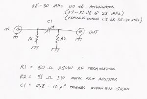
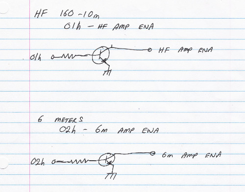
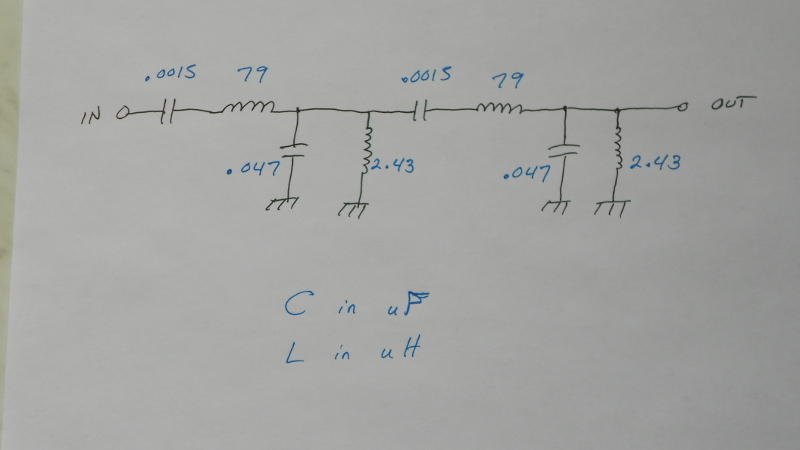
Schematic diagram and parts list for the attenuator

I had some 250 watt, 50 ohm RF load resistors on hand. One of those would make a fine input resistor for a pi network attenuator. I had some 51 ohm, one watt metal film resistors. One of those would do fine for the output. But for 40 dB attenuation, the series resistor in the pi network would have to be 2500 ohms at around 2 watts. I didn’t have something like that and trying to make one out of a series-parallel combination of resistors might add considerable stray capacitance. Ordinarily that might not matter too much at 28 MHz, but when making a 40 dB attenuator, stray capacitance could tend to “bypass” the resistor and cause the attenuation to be too low. However, there is another trick that can be used. The series resistive element can be replaced by a capacitor having reactance equal to the required resistor value at the frequency of interest. That works out to about 2.3 pF in this case. That is not much, but I had some Johanson 5200 0.8 to 10 pF muti turn air trimmers around. If I could keep circuit strays low enough or shield input from output that should work. Using a variable element would allow me to “dial in” the proper amount of attenuation, compensating for circuit strays (as long as they weren’t too great). There is a caveat when using a capacitor for the series element in a pi network attenuator. Attenuation will not be constant over a wide frequency range, because the reactance of the capacitor is frequency dependent. That wasn’t a problem for my intended use, since only a narrow frequency range is involved.

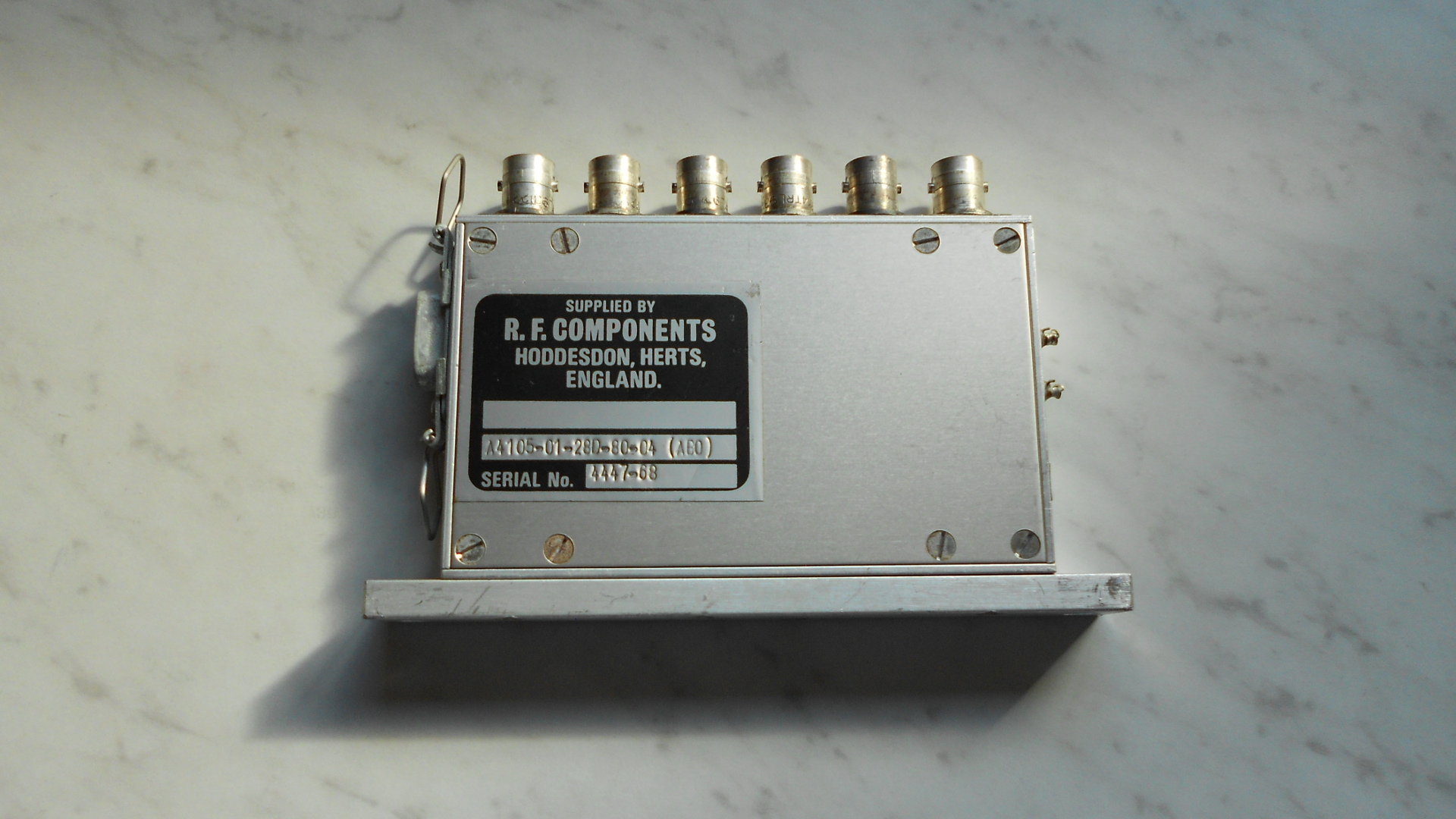
I needed a heat sink that could handle 100 watts intermittent duty. I immediately remembered I had some old repeater parts that might do the trick. Some folks might shoot me for this, but I grabbed a NOS Motorala MICOR UHF base station antenna network. This is a circulator, relay, filter and some other bits on a nice heat sink! I stripped all the rubbish off and there was my heat sink, ready to go. It’s a bit of an irregular shaped thing and has some extraneous holes here and there, but who cares? I was going to hide it behind a rack of equipment anyway. The antenna network also provided a type N female bulkhead  connector with a short length of RG-400 coax already connected t it, as well as a BNC female bulkhead connector with a similar RG-400 lead. Wahoo! There were my input and output connections for the attenuator. I clipped them off before tossing the rest of the antenna network in my electronic refuse bin. RG-400 is nice stuff: Teflon dielectric, double silver plated braid, stranded silver plated center conductor. You can’t melt this stuff with soldering heat! All the better. A little more digging turned up a small cast aluminum box which I could use to house the attenuator components.

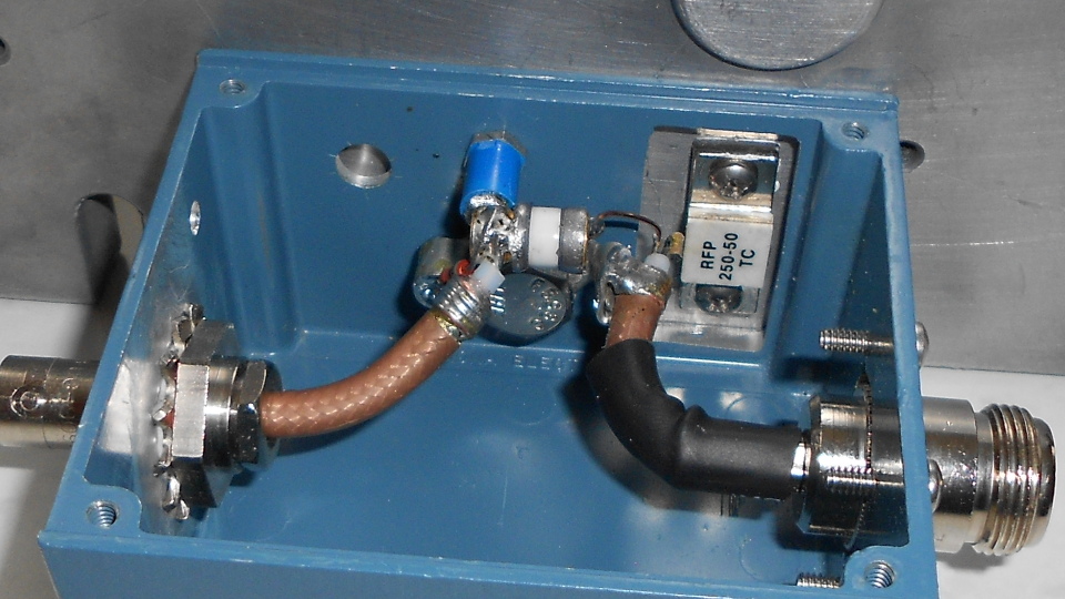
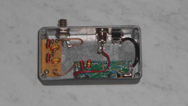
Inside view of attenuator with cover removed

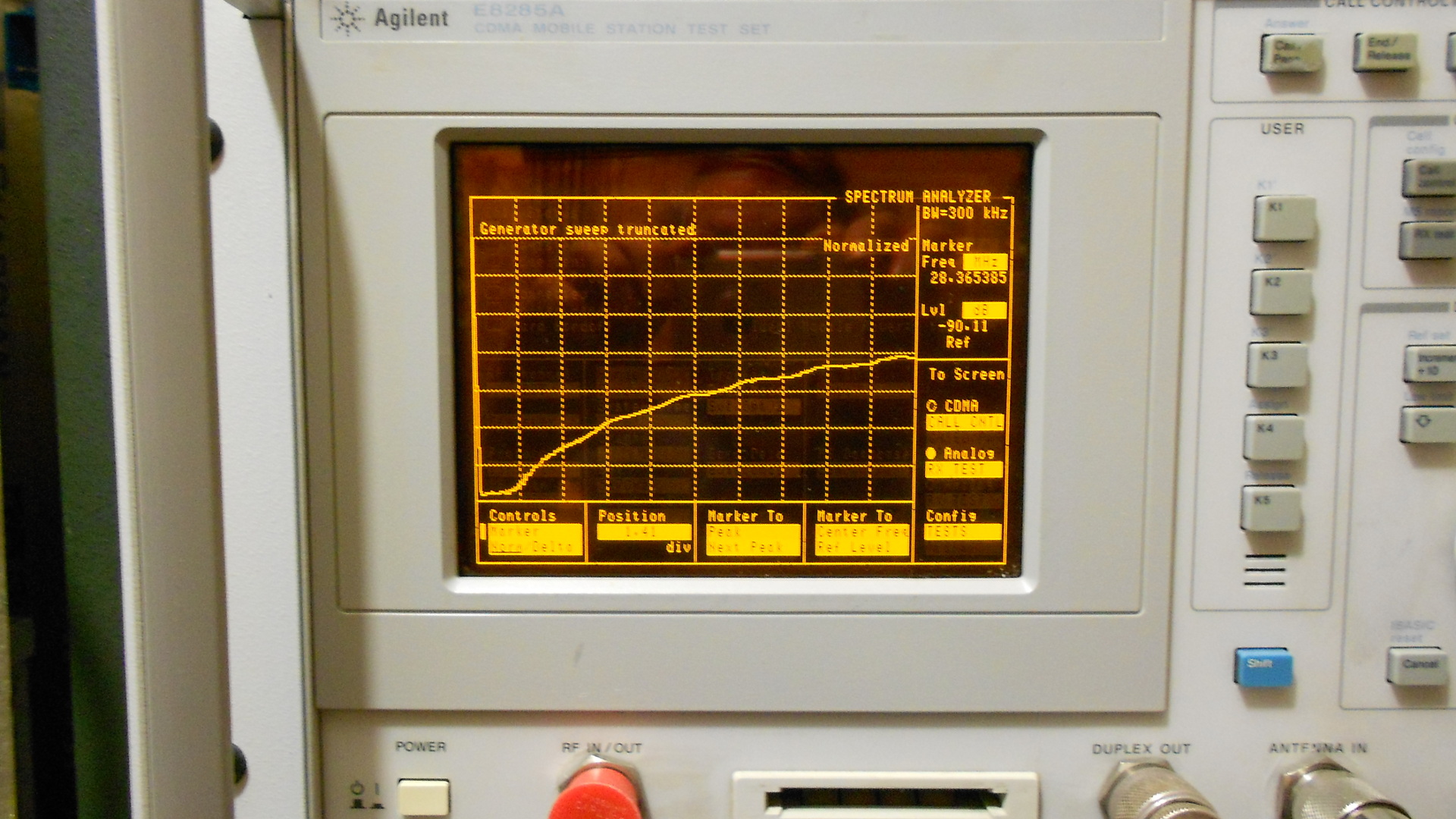
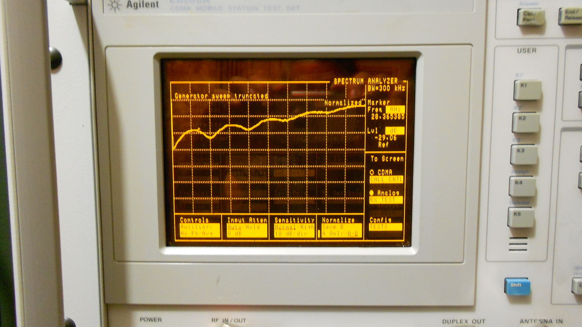
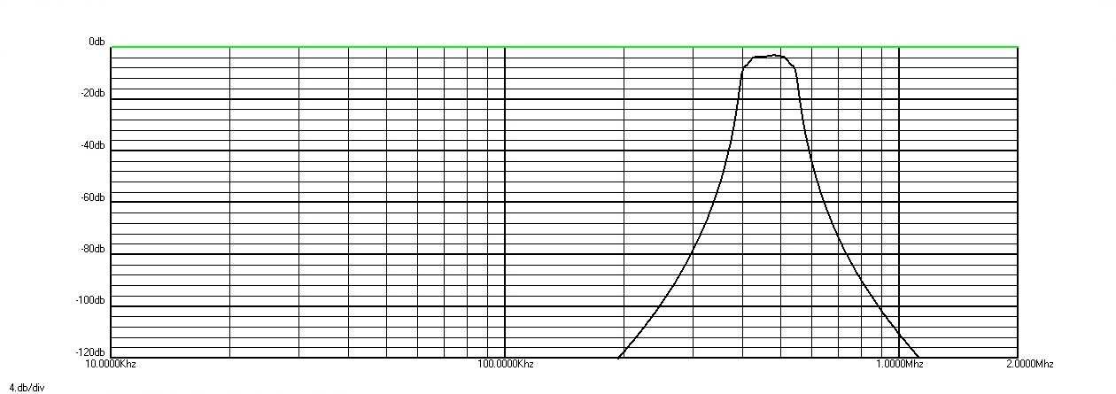
I exercised some care in circuit layout and lead dress. I also left the shield on input and output coax as close to the end as possible in the hope that this might eliminate any need for a shield between input and output. After putting the circuit together I checked it on a spectrum analyzer / tracking generator. To my delight I found that using the trimmer I could vary the attenuation from 27 to 51 dB at 28 MHz. Wow! My circuit layout and construction was good enough. Flatness of attenuation over the 26 to 30 MHz range was within 1.5 dB. That is fine. In practice it will only be used over a 200-300 kHz range with any given transverter, and each transverter has its own built in adjustable input attenuator to fine tune its drive level. Attenuation slope over a 300 kHz range is too little for me to measure but probably about 0.1 dB. Return loss (input SWR) is better than my ability to measure, which is limited to about 30 dB RL (1.07 SWR). Plenty good enough.

One final note. I stripped the paint off the surface of the box that mates with the heat sink and from around the hole where the BNC connector is. Was this necessary? I don’t know but my standard operating procedure for RF circuits is to remove paint between mating surfaces in the enclosure or where connectors attach. I find it easier to do this in the first place than to disassemble something and strip paint after finding there was a problem!

2200m/630m Transatlantic Reception, January 26 to February 2

The past few nights have been very interesting on LF and MF. For starters, January 29 was the first time I heard Europe on 2200 meters. I have decoded at least one transmission from Europe on the band each of five nights since then. This may be in whole or in part due to a change I made to my receiving setup on January 29. However, a number of other curious things emerge when looking at the data.

For one thing, I did not decode any 630m transatlantic signals on the night of January 28/29, but I did decode DC0DX four times on 2200m.

The second thing of note is the decodes on the night of February 1/2. On 630 meters I only decoded EA5DOM, which is quite low latitude for a transatlantic path. The northern stations were completely missing, not only from Europe but also no transcontinental decodes from the VE7 or northern W7 areas. This would be a typical pattern given an upturn in geomagnetic activity from mostly quiet to active/minor storm. Yet this was the second best night for transatlantic on 2200m with three DC0DX decodes, including the best S/N yet observed.

The other thing of interest is that on 630m, excepting an early start by PA0A on the night of January 31/February 1, most of the decodes are about in the middle of common darkness; not near my sunset or near sunrise at the eastern end of the path. There is one late decode of EA5DOM on the night of January 30/31. On 2200 meters we find most of the decodes were late, not too long before sunrise at the eastern end. The only exception is three earlier decodes of DC0DX on the night of January 28/29.

Although not shown here, WH2XND on 2200m was notably weaker on the final night, February 1/2 than on the previous nights in this period.

There is insufficient data to draw any conclusions, but in the early days of hearing transatlantic signals on 2200m it does not seem to correlate well with what is happening on 630m. I wonder if any clear trends will emerge as more data is accumulated.


Transatlantic decodes, 630m, January 26 – February 2:

2017-01-30 02:36 EA5DOM  0.475610 -26 IM98xn N1BUG FN55mf 5578 301 
2017-01-30 02:48 EA5DOM  0.475610 -27 IM98xn N1BUG FN55mf 5578 301 

2017-01-31 00:12 EA5DOM  0.475610 -26 IM98xn N1BUG FN55mf 5578 301 
2017-01-31 01:12 G3KEV   0.475705 -23 IO94sh N1BUG FN55mf 4820 287 
2017-01-31 01:20 G3KEV   0.475705 -25 IO94sh N1BUG FN55mf 4820 287 
2017-01-31 03:16 ON5TA   0.475671 -27 JO20es N1BUG FN55mf 5264 293 
2017-01-31 06:24 EA5DOM  0.475609 -28 IM98xn N1BUG FN55mf 5578 301 

2017-01-31 21:48 PA0A    0.475730 -25 JO33de N1BUG FN55mf 5280 292 
2017-01-31 21:50 PA0A    0.475730 -27 JO33de N1BUG FN55mf 5280 292 
2017-01-31 23:50 PA0A    0.475730 -29 JO33de N1BUG FN55mf 5280 292 
2017-01-31 23:54 PA0A    0.475730 -27 JO33de N1BUG FN55mf 5280 292 
2017-02-01 00:24 G8HUH   0.475782 -26 IO81mg N1BUG FN55mf 4766 289 
2017-02-01 00:24 EA5DOM  0.475610 -27 IM98xn N1BUG FN55mf 5578 301 
2017-02-01 00:44 G8HUH   0.475782 -26 IO81mg N1BUG FN55mf 4766 289 
2017-02-01 00:48 EA5DOM  0.475610 -29 IM98xn N1BUG FN55mf 5578 301 
2017-02-01 00:54 G8HUH   0.475782 -22 IO81mg N1BUG FN55mf 4766 289 
2017-02-01 02:48 EA5DOM  0.475609 -27 IM98xn N1BUG FN55mf 5578 301 
2017-02-01 03:36 EA5DOM  0.475609 -28 IM98xn N1BUG FN55mf 5578 301 
2017-02-01 03:44 F1AFJ   0.475727 -28 JN06ht N1BUG FN55mf 5193 295 
2017-02-01 04:00 EA5DOM  0.475609 -30 IM98xn N1BUG FN55mf 5578 301 

2017-02-02 02:36 EA5DOM  0.475610 -28 IM98xn N1BUG FN55mf 5578 301 
2017-02-02 03:24 EA5DOM  0.475609 -25 IM98xn N1BUG FN55mf 5578 301

Transatlantic decodes, 2200m, January 26 – February 2:

2017-01-29 01:20 DC0DX 0.137469 -27 JO31lk N1BUG FN55mf 5399 294 
2017-01-29 02:18 DC0DX 0.137469 -24 JO31lk N1BUG FN55mf 5399 294 
2017-01-29 04:14 DC0DX 0.137469 -27 JO31lk N1BUG FN55mf 5399 294 
2017-01-29 07:08 DC0DX 0.137468 -27 JO31lk N1BUG FN55mf 5399 294 

2017-01-30 06:12 DC0DX 0.137468 -25 JO31lk N1BUG FN55mf 5399 294 

2017-01-31 07:20 G8HUH 0.137425 -28 IO81mg N1BUG FN55mf 4766 289 

2017-02-01 07:10 DC0DX 0.137469 -27 JO31lk N1BUG FN55mf 5399 294 

2017-02-02 05:36 DC0DX 0.137469 -23 JO31lk N1BUG FN55mf 5399 294 
2017-02-02 05:58 DC0DX 0.137469 -24 JO31lk N1BUG FN55mf 5399 294 
2017-02-02 06:20 DC0DX 0.137469 -25 JO31lk N1BUG FN55mf 5399 294

2200 Meter SoftRock Lite II

Any good project starts with some scribbling on paper…

With the 630 meter SoftRock Lite II working well it was time to turn my attention to putting one on 2200 meters. There is no standard SoftRock which covers this range so I would have to make a few component substitutions. The changes are all very minor except for the crystal which cost more than the SoftRock kit! Something around 455 kHz is ideal. I ended up buying a 455 kHz carrier crystal from INRAD. Several capacitors in the oscillator would need to be changed to higher values, namely C10 3900 pF, C11 2700 pF, and C12 680 pF. I also changed R16 to 10k ohms because I find the oscillator never runs properly with the stock value.

The front end was also going to need some changes. C3 becomes .005 uF. C4 should be .16 uF but I used a .15 and it worked well enough. L1 is 267 uH. I used 25 turns on a FT-37-43 core. T1 primary should be 8.23 uH. I used 12 turns on a FT-37-61 core. The secondary is 6 bifilar turns. This input circuit has a bit of loss (about 2 dB) but I considered that acceptable since I was unable to come up with a better design that was also practical. As with the 630 meter unit, additional front end selectivity would be needed. I duplicated the C3, L1, C4, T1 primary once more and placed the circuit on a small prototype board.

Internal view of completed receiver

The finished receiver works well. I have been hearing WH2XND very well every night. I have heard Europe on WSPR-2 mode four consecutive nights, three of those nights DC0DX and the one night G8HUH. There were no problems with out of band signals until I added a preamp, at which time I had to put an outboard bandpass filter in line to keep things clean. LO frequency stability is on par with the 630 meter unit. See my earlier performance evaluation on that for details. I am happy with the performance and this is now my primary 2200 meter receiver.

Final Test of SoftRock Lite II on 630-Meters

Response curve of three section filter

I built a small two stage band pass filter that fits in the box with the SoftRock. Essentially I took the half wave input filter used in the receiver front end and duplicated it twice, including the shunt inductance of the input transformer. Combined with that already on the SoftRock itself, this provides a three section filter which is more than 100 dB down at the second harmonic of the local oscillator (and much more at the third harmonic). Performance of the filter was verified on a spectrum analyzer after construction. It is virtually identical to the modeled plot shown here. It is always good when real world results match the design model!

Return loss of the three stage input filter

Some will argue that this filter is too simplistic. That may be true from a purist standpoint, but results have proved more than adequate. I wouldn’t call it a state of the art design. However it is very inexpensive and fits in a small space. Pass band loss is about 5 dB, mostly due to Q of the inductors. I wasn’t able to come up with a filter that looked better on reasonable size toroids without running into issues with overlapping turns and distributed capacitance causing problems. With any practical antenna (and preamp if needed) I don’t see this loss as a problem. Return loss isn’t great, but exceeds 10 dB across the pass band, which is approximately 420 to 520 kHz. In a receive application I see no problem with this. The input impedance of receivers is all over the place, some much worse than this one.

Live results are gratifying. Even with one of my 22 dB gain W1VD preamps in line, there was no sign of broadcast stations appearing in the useful range of the receiver. (Note: I don’t need the preamp with my receive antennas. I only used it as an acid test to evaluate filter performance, since it makes the signals we want to reject that much stronger.)

Inside the completed receiver

The receiver and filter fit nicely into a Hammond 1590BBK diecast box which gives it a nice look in a compact package. I probably didn’t need to use miniature coax (in this case RG-188) for the very short runs interconnecting the BNC input connector, filter board, and SoftRock. At this frequency and with this layout, the very small capacitance between unshielded wire leads would probably not cause harmful leakage around the filter. But I have a bunch of this stuff, so why not use it? Besides, the teflon cable is a joy to work with. The insulation on most of the small hookup wire I have melts easily while soldering. Not this stuff!

Building this receiver was a pleasant and worthwhile experience. I finally understand how simple SDRs work. Studying the schematic, reading the descriptions of individual stage function, building it and probing various locations in the receiver with an oscilloscope and spectrum analyzer was very enlightening. I learned more about filters. Perhaps most importantly, I am no longer afraid of projects involving surface mount components. Performance of the completed receiver is good enough that I can recommend it to anyone wanting a simple, inexpensive receiver for the 630 meter band or anything else in the 420 to 520 kHz range (with a sound card sampling at 192 kHz the receiver will tune 368 to 560 kHz, but the filter cuts off at 420 and 520 kHz). It outperforms my FT-2000 in every measurable way. If there is one caveat it would be that if one wished to use it for serious reception of QRSS or DFCW signals it either needs to be well insulated or have a crystal heater added. For everything else its frequency stability is excellent. To my knowledge there is no QRSS or DFCW activity on 630 meters at the present time.

Update 19 January 2018: Adding schematic for the two additional stages of front end filtering. Coils are the same as those in the Softrock Lite II 455 kit.

External band pass filter schematic